41 heat trace wiring diagram
Chromalox Heater Wiring Diagram Heat Trace Skid Systems · ITAS-EXT Installation Manual. Chromalox Technical Documents Technical Technical Information Three Phase Equations & Heater Wiring Diagrams Typical Heater Wiring Diagrams Three. Phone: wiringall.com 1. Wire all heaters and controls in accordance with the appropri- ate wiring diagram provided below. Marvelous Raychem Heat Trace Wiring Diagram 220 Volt Motor Marvelous Wiring Trace Diagram Volt Motor Raychem 220 Heat A Wiring Diagram Is A Simplified Standard Photographic Depiction Of An Electrical Circuit. Marvelous Wiring Trace Diagram Volt Motor Raychem 220 Heat The 9200i Establishes Wireless Connectivity Between Nvent Raychem Electric Heat Trace Controllers And Nvent Raychem Supervisor Software ...
PDF Nelson Heat Tracing Systems Specification / Application ... WIRING DIAGRAM Power Supply Heater Cable Nelson Heat Tracing Systems products are supplied with a limited warranty. Complete Terms and Conditions may be found on Nelson's website at . P.O. BOX 726 TULSA, OK 74101 TEL 918-627-5530 FAX 918-641-7336
Heat trace wiring diagram
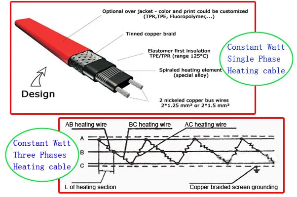
Electrical Heat Tracing | Heat Tracing | nVent Dec02 nVent RAYCHEM HTV Heat Tracing Cable Secures Independent UL Verified Mark . LONDON- December 2, 2021 - nVent Electric plc (NYSE:NVT) ("nVent"), a global leader in elect... Nov18 nVent Integrates Advanced Work Packaging and Heat Mapping into 3D Electric Heat Tracing Design Software . LONDON - November 16, 2021- nVent Electric plc (NYSE:NVT) ("nVent"), a global leader in ... Heat Trace Wiring Diagram Collection Heat Trace Wiring Diagram. Effectively read a wiring diagram, one has to find out how the components within the system operate. For instance , when a module will be powered up and it also sends out a new signal of fifty percent the voltage and the technician will not know this, he'd think he offers an issue, as he would expect the 12V signal ... Electrical Heat Tracing - InstrumentationTools Constant power heat tracing cable sometimes referred to as series resistance cable is made up of a high-resistance wire that is typically insulated and encased in a protective cover. When powered at its operating voltage, thermal energy is produced from the resistance of the wire. Advantages of constant power trace heating cables include:
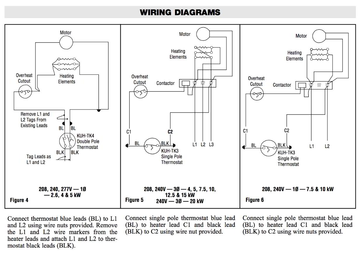
Heat trace wiring diagram. PDF CT-FL C APSTAT - Heat Trace Users of Heat Trace Ltd products should make their own evaluation to determine the suitability of each such product for specific applications. n no way will eat Trace Ltd be liable for any damages arising out of the misuse resale or use of the product. Heat Trace Ltd, Mere's Edge, Chester Road, Helsby, Frodsham, Cheshire, WA6 0DJ, England. PDF NELSON HEAT TRACE - Emerson Electric The Nelson Heat Trace CM-2201 is designed to monitor and controloneheating circuitinordinaryandClassI,Division 2, ClassI,Zone2,andZone2 hazardous locations. The CM-2202 can monitor/control two heating circuits in those same locations. Heat Trace Wiring Diagram Gallery - Wiring Collection Feb 26, 2018 · heat trace wiring diagram – A Newbie s Overview of Circuit Diagrams An initial take a look at a circuit representation might be confusing, but if you could check out a subway map, you can review schematics. The function is the exact same: obtaining from factor A to direct B. Literally, a circuit is the path that enables electricity to circulation. PDF Chromalox Three Phase Equations and Heater Wiring Diagrams Typical Heater Wiring Diagrams The following diagrams show typical heater wiring schematics. Single Phase AC circuits where line voltage and current do not exceed thermostat rating. Three Phase AC heater circuit where line voltage and current do not exceed thermostat rating. Circuit does not have a "positive" off.
Raychem Heat Trace Wiring Diagram Jan 29, 2019 · Raychem Heat Trace Wiring Diagram. Do not use this kit with aluminum feed wires. For additional For WinterGard Wet heating cables H and H in roof and gutter de-icing . If no number appears in the cell, straight trace the pipe. . at 2-foot intervals using Raychem H This RAYCHEM heat trace system provides pipe freeze protection for metal and ... Special Installation Instructions Supplement Duct-o-bar ... provided Heat Trace Wiring diagram. • Power must stay on to the Heater Control Panel for system to work properly. Power should be brought to Heater Control Panel from separate disconnect. • Heater Control Panel wiring diagrams and external heater cable circuit wiring diagrams are provided with the system. Chromalox Installation Manuals Series Resistance Long Line - Heat Trace. Industrial Heating Cable Products Installation Manual PJ438 Silicone Heaters. Installation Instructions: Laminated Silicone Rubber Heaters PL401 ... IntelliTrace Modbus Wiring & Registry Map Instructions PDF TraceNetTM Control and Monitoring System TCM2 - Thermon Heat Trace Mains Supply 100 to 600 V~, 50/60 Hz (See Table 2.2 for Control Module supply information) Control Points Up to 2 Heat Tracing Circuits Heat Trace Current See Table 2.3: Maximum Heater Current Through Each Solid State Relay Temperature Inputs Up to Two per Control Point; Platinum RTDs 100 Ω @ 32 °F (0 °C) Temperature Control
Wiring Diagram - Urecon Heat Loss Calculations and System Design. Electric Heat tracing ... NGUTC-2030 and NGUTC-2230 . Thermostats. Specifications; Three-Phase Contactor . Thermostat. Program Codes. Wiring Diagram. Mechanical Controllers. Submittal Data Sheets. Installation Guides : Wiring Diagram. NGUTC-2030 & NGUTC-2230. PDF Heat Trace Tube Bundle Installation - Mustang Sampling 2. Drill a hole that matches the internal part of the heat trace boot through the enclosure. 3. Attach and tighten the heat shrink boot to the enclosure. 4. Run heat trace through the seal fitting prepped for the heat trace. 5. Connect the heat trace wiring to the wires in the explosion proof crock. 6. Install the valve and terminate the tubing. 7. PDF Design Guide and Installation Details for ... - Heat Trace heat trace pipes, valves and flanges. Alternate Voltages RSCC 240 VAC self-regulatingheating cables can be operated at alternative voltages. The chart below compares heating cable power output with prod-uct rating. Power Adjustment Factor Part No. 208 Volts 277 Volts 2703-2 .75 1.28 2705-2 .86 1.16 PDF 3M Self-Regulating Heat Tracing Cables The diagrams and instructions outlined in this guide are for illustration purposes only. They are not necessarily to scale and do not necessarily represent exact real-world heat tracing systems. In addition, they are not meant . or implied to be a replacement for a licensed professional. Any use of 3M Heat Tracing Cables must be in
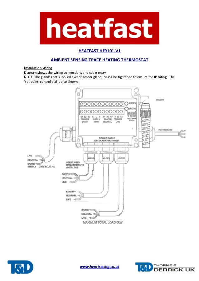
HEATFAST HF9101-v1 Ambient Sensing Heat Tracing Thermostat ...
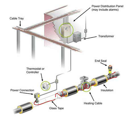
Heat Tracing - Urecon Heat Tracing. To compensate for heat losses and to maintain a minimum temperature (i.e. to prevent freezing), an electric heat tracing system can be used. In most cases, a THERMOCABLE® heat tracing cable is pulled into trace conduits in long circuit lengths, after the pipes have been field assembled.

NVENT THERMAL 8W/FT 208-277V XL-Trace Self-Regulating Heating Cable - Polyolefin Outer Jacket, Orange
Design, Installation and Maintenance Manual - Heat Trace Maintenance of electric heat tracing systems shall conform to all IEC requirements for the use of electrical equipment and with the requirements of the relevant heat tracing standard, usually either IEC 62395 Electrical resistance trace heating systems for industrial and commercial applications or IEC 60079-30 Explosive atmospheres - electrical

CTS Commercial Heat Trace Electronic Thermostat
EasyHeat™ Pipe Tracing Controls | Emerson US EasyHeat™ pipe tracing controls are intended for temperature control of a variety of electric heating cables and applications. They include the C3RC, C4XC, T4XC, T4XA, T9EC, T9EA, SMC54WP, and SMC51/SMC52 thermostats.
ThermaTrace - Heat Tracing Experts ::
240 Volt Electric Heater Wiring Diagram - U Wiring 7500 watt garage heater and remote diy how to make a smart dimplex 5000w 240 v sylvania model sich diagram heat trace 240v wiring 277v thermostat what dyna glo pro king gh2407tb volt please help me rewire water universal switch one 220 electric furnace sizing the circuit cadet hot 5000 single pole old adding low voltage important instructions read.
RSX™ 15-2 - Prozessheizungslösungen
PDF TRACEMATE-277V - NextronUSA.com voltage range of the heat trace cable. Wiring methods must conform to Class 1, Division II or Class 1, Zone II requirements. Heater Wiring Connect heatingcable wiring toterminals3 and 4.See Figure 2.2. If the heating cable has a braid, it should be terminatedtothe ground studusing a ring terminal suitable for #10 stud. Figure 2.3 GroundConnection

Flow Maintenance | Grease Waste Management | nVent
PDF Heat Trace Design Guide - ARCO Engineering Electric heat tracing systems are designed to make up for the heat lost from process system equipment through the thermal insulation. In some cases, the heat tracing system can be used for system heat-up at initial startup or after a power shutdown. The information in this design guide will allow the
Factory Wholesale Heat Tracing Cable 15w For Driveway Gutter ...
Heat Trace and GFCI, GFEP | Mike Holt's Forum Nov 19, 2010. #1. I have a situation where I have outdoor heat trace cables (2 @ approx. 100' @ 5w/ft.) that I would like to design to plug into outdoor receptacles (on the same circuit). I realize that by NEC code, I should put the circuit on a GFEP type breaker. My question is if I should utilize a GFCI receptacle for the outdoor location.

Electric Heat Tracing System Installation Guide for ...
Electric Heat Tracing - Thermon isometric system diagrams (if provided). • Lay out the trace heater on the pipe, at the 4 or 8 o’clock position (Illustration B), securing it tightly against the pipe with attachment tape. Wrap bands of tape around the trace heater and pipe at intervals of 12” (30 cm) or less, keeping the trace heater in close contact with the pipe.

How to Select, Install, Operate and Maintain Electric Heat ...
Heat Trace Wiring Diagram Sample - Wiring Diagram Sample Jun 21, 2018 · heat trace wiring diagram – What’s Wiring Diagram? A wiring diagram is a kind of schematic which uses abstract pictorial symbols to show each of the interconnections of components in a system. Wiring diagrams comprise a couple of things: symbols that represent the components inside circuit, and lines that represent the connections together.
Chromalox thermostat wiring diagrams for HVAC systems ...
PDF C910-485 Heat Trace Controller - nVent INSTALLATION AND WIRING 2.1 INTRODUCTION This section includes information regarding the initial inspection, preparation for use, and storage instructions for the C910-485 Heat Trace controllers. 2.2 INITIAL INSPECTION Inspect the shipping container for damage. If the shipping container or cushioning

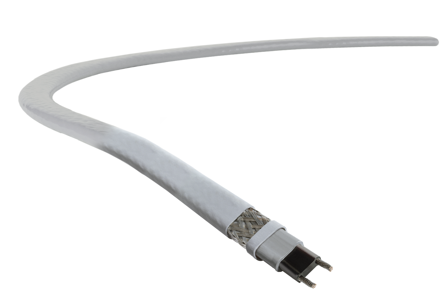
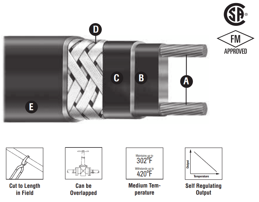
Heat Tracing Cable Cross Section - Heating and Process
PDF DigiTrace 910 Series Heat Trace Controller The 910 Series electronic Heat Tracing Controller controls, monitors, and communicates alarms and data for one heating circuit. The ability to install the units in Class 1, Division 2 areas supports
Single Point General Purpose Heat Trace Controller
Installation, Operation and Maintenance Manual for The ... 2.2 General Wiring Diagram 3 2.3 Heater Connection 3 2.4 Power Connection 4 2.5 Signal Connections 4 2.6 RTD Connections 4 ... RTDs and cord grips pre-wired from HTD Heat Trace with 10' long leads. When ... fully insulated terminals for 16AWG wire and ¼" wide x 1/32" thick tab.

Heat Tracing | 2012-09-01 | Process Heating
Electrical Heat Tracing - InstrumentationTools Constant power heat tracing cable sometimes referred to as series resistance cable is made up of a high-resistance wire that is typically insulated and encased in a protective cover. When powered at its operating voltage, thermal energy is produced from the resistance of the wire. Advantages of constant power trace heating cables include:
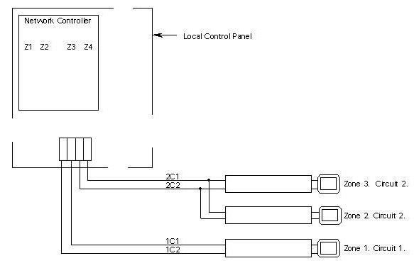
Wiring Diagram
Heat Trace Wiring Diagram Collection Heat Trace Wiring Diagram. Effectively read a wiring diagram, one has to find out how the components within the system operate. For instance , when a module will be powered up and it also sends out a new signal of fifty percent the voltage and the technician will not know this, he'd think he offers an issue, as he would expect the 12V signal ...
WH7016E temp controller & Cedaronics Enclosure/heat trace ...
Electrical Heat Tracing | Heat Tracing | nVent Dec02 nVent RAYCHEM HTV Heat Tracing Cable Secures Independent UL Verified Mark . LONDON- December 2, 2021 - nVent Electric plc (NYSE:NVT) ("nVent"), a global leader in elect... Nov18 nVent Integrates Advanced Work Packaging and Heat Mapping into 3D Electric Heat Tracing Design Software . LONDON - November 16, 2021- nVent Electric plc (NYSE:NVT) ("nVent"), a global leader in ...
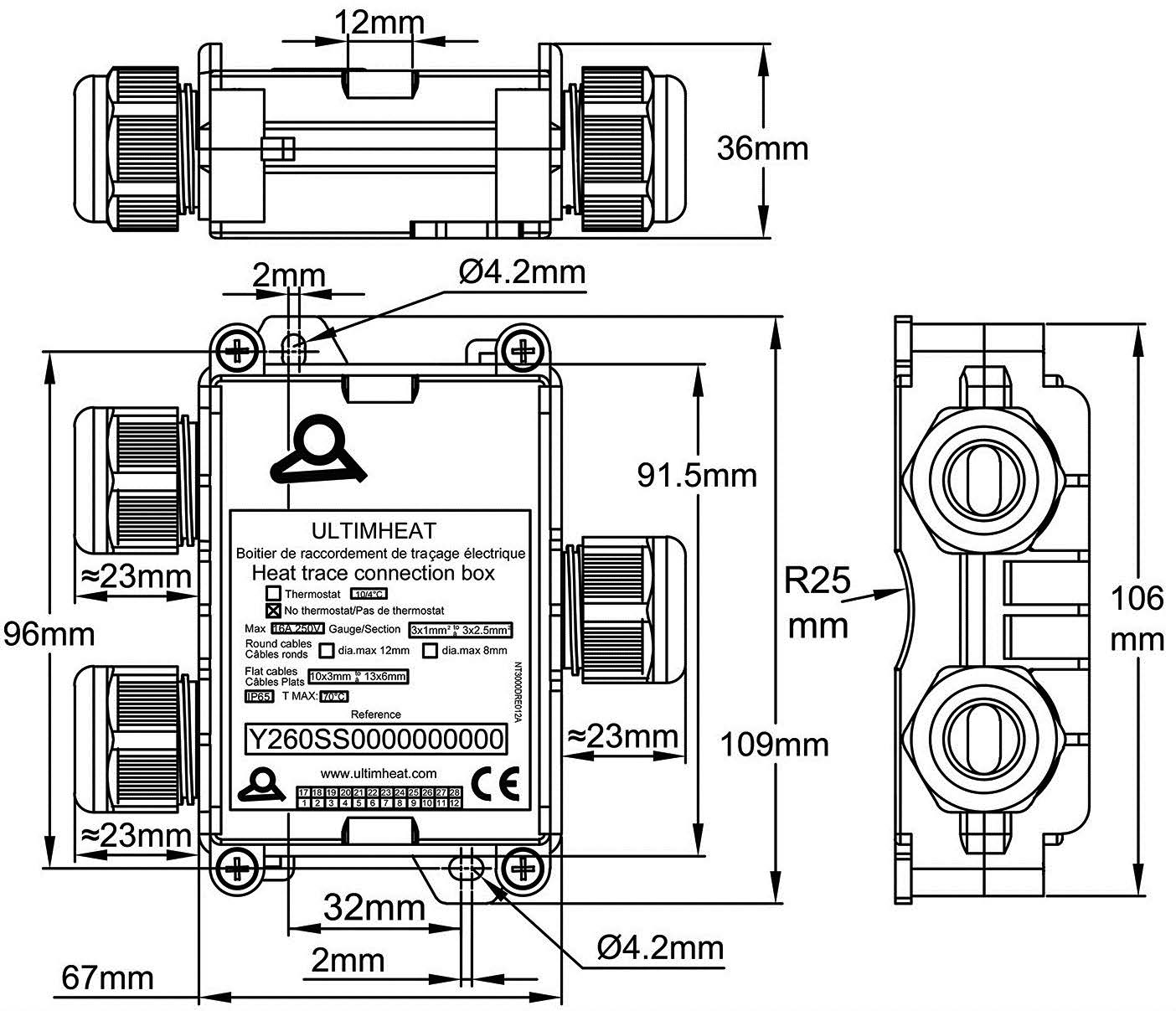
T connection box for heat tracing cables with antifreeze ...
Design Guide

5 w/ft 120v Self Reg Heating Cable Fluropolymer Jacket
Design Guide
Intech 21, Inc. - HCCM-2100 Heater Cable Control and ...

Pipes Heating Cable Self regulating Heating Trace cable - YouTube

Electric Heat Tracing System Installation Guide for ...

Begleitheizungs-Verbindungssätze

Pipe Heat Trace | Heat Trace Cable | nVent

Unauthorized changes to alarm configuration should be checked ...
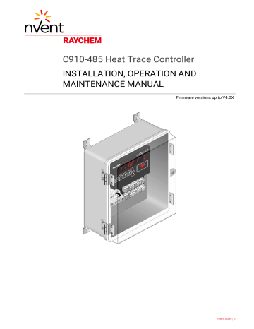
Raychem C910-485 Installation Manual | Manualzz

Installation Manual of heat tracing cable
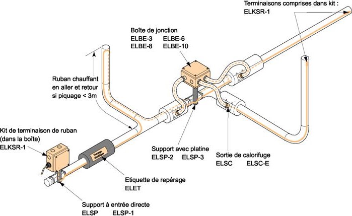
Choisissez votre câble chauffant en fonction de votre ...

465 Electronic Controller for Heat Tracing of Fire Protection ...
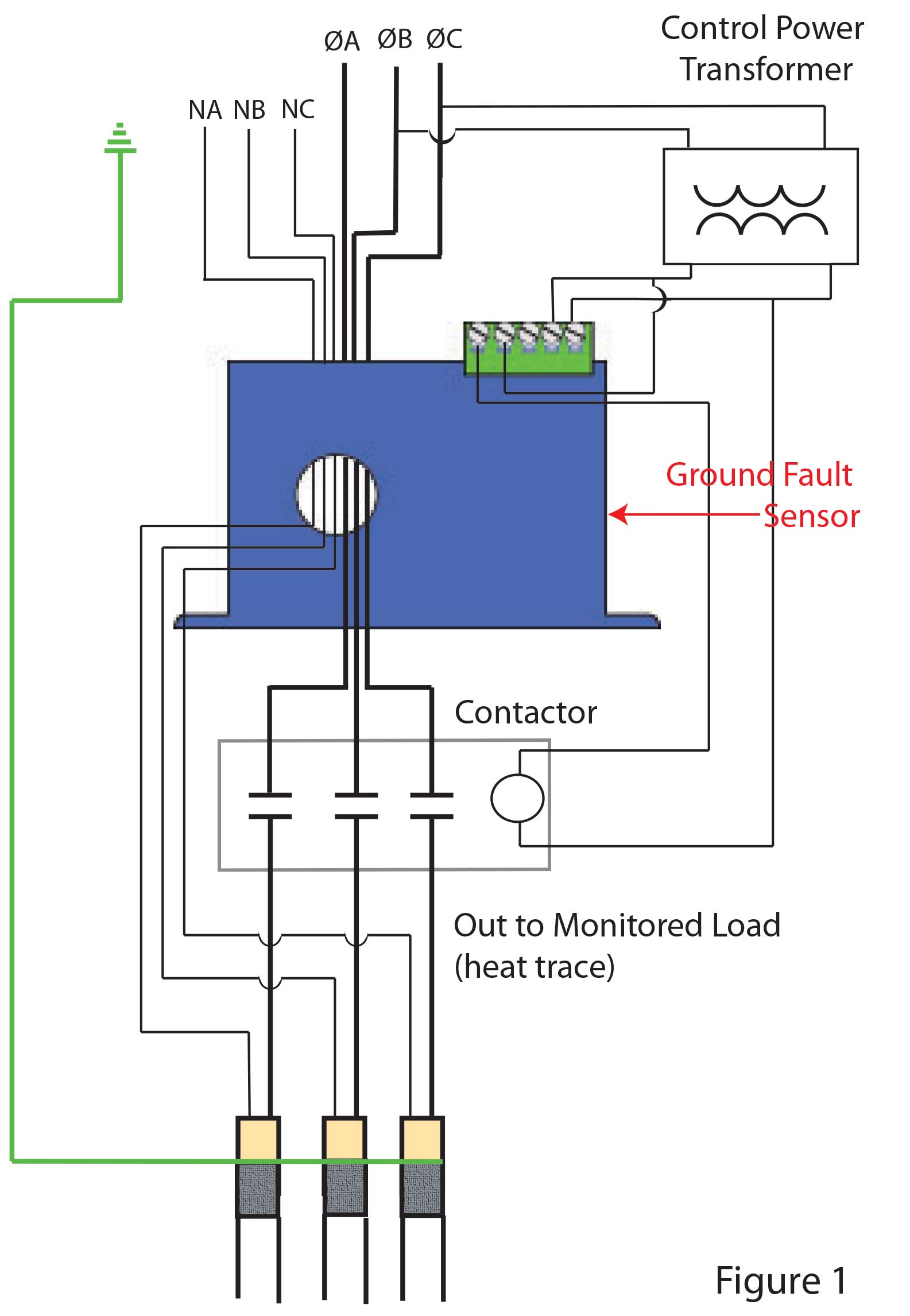
Monitoring Ground Faults of Heat Trace Systems - NK Technologies
Chromalox HSRM 15 | 15W/FT 120V 240V Trace Heating Cables
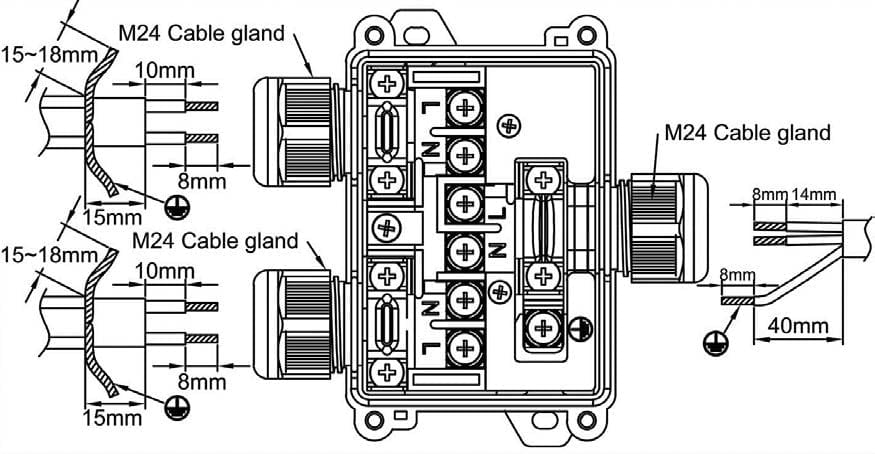
T connection box for heat tracing cables with antifreeze ...

Chromalox Installation, Operation Industrial Heating Cable ...

The Basics Of Electric Heat Trace Technology - CrossCo

Heat Tracing short located with a TDR - Delta Automation

Elettrico sistema di rintracciamento di calore
Chromalox | Heat Tracing | Installation Manual | EN-US
KM26 Magnetic level gauges
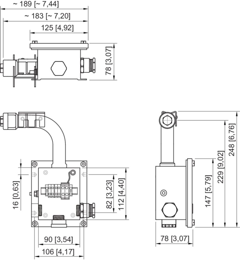
Junction box for heat tracing For pipe mounting - 259479
Industrial heat tracing solutions
Chromalox | Heat Tracing | Installation Manual | EN-US
0 Response to "41 heat trace wiring diagram"
Post a Comment