40 free body diagram beam
PDF ENGR-1100 Introduction to Engineering Analysis Idealized model Free-body diagram (FBD) 1. Draw an outlined shape. Imagine the body to be isolated or cut "free" from its constraints and draw its outlined shape. FREE-BODY DIAGRAMS (continued) 3. Label loads and dimensions on the FBD: All known forces and couple moments should be labeled with their magnitudes and directions. PDF BEAM DIAGRAMS AND FORMULAS - Arch Exam Academy beam fixed at one end, free to deflect vertically but not rotate at other-concentrated load at deflected end 24. beam overhanging one support-uniformly distributed load. 25. beam overhanging one support-uniformly distributed load on overhang ... microsoft word - beam diagrams and formulas.doc author: momo created date: 12/13/2006 8:53:15 am ...
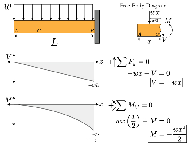
How to Calculate Bending Moment Diagram? - SkyCiv Once you have the reactions, draw your Free Body Diagram and Shear Force Diagram underneath the beam. Finally calculating the moments can be done in the following steps: 2. From left to right, make "cuts" before and after each reaction/load To calculate the bending moment of a beam, we must work in the same way we did for the Shear Force Diagram.

Free body diagram beam
Free body diagram for beam with pin-pin supports ... Download scientific diagram | Free body diagram for beam with pin-pin supports from publication: Requirements Analysis for Engineering Computation: A Systematic Approach for Improving Reliability ... What is a Free-Body Diagram and How to Draw it (with ... A free-body diagram is a representation of an object with all the forces that act on it. The external environment (other objects, the floor on which the object sits, etc.), as well as the forces that the object exerts on other objects, are omitted in a free-body diagram. Below you can see an example of a free-body diagram: PDF Free Body Diagrams - Memphis 8 Free Body Diagrams Wednesday, October 3, 2012 ... right end of the beam and replace it by an x and a y reaction component F S W F PY F PX 44 Free Body Diagrams Wednesday, October 3, 2012 New Support Conditions Pin Connection ! The notation is clumsy here, we will try to be
Free body diagram beam. Beam Calculations Made Easy - From Free Body to Stress ... Once you have your loads, create a free body diagram showing each load and where it occurs on the beam. It doesn't have to be exactly to scale, but it helps if it is close. Be sure to leave room directly below the beam so that we can draw our shear-moment diagram! Beam Reaction and Free Body Diagram Example Problem Free Body Diagram and Reactions of a Beam. Given: the beam and loading as shown. Determine: the magnitude of the reactions at A and B after drawing a FBD of the system. Solution: The reactions at A and B are replaced by forces at A and B. The force at B must be vertical because its roller support can only react perpendicular to the surface upon ... Cantilever Free Body Diagram Example | Statics - YouTube for more FREE video tutorials covering Engineering Mechanics (Statics & Dynamics)The key objective of this video is to consider support... Free Online Beam Calculator | SkyCiv Engineering Free online beam calculator for generating the reactions, calculating the deflection of a steel or wood beam, drawing the shear and moment diagrams for the beam. This is the free version of our full SkyCiv Beam Software. This can be accessed under any of our Paid Accounts, which also includes a full structural analysis software.
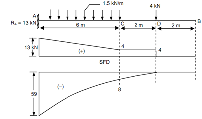
Answered: Draw a free body diagram of the beam… | bartleby For the beam and loading shown, use the double-integration method to determine (a) the equation of the elastic curve for the beam, (b) the slope at A, (c) the slope at B, and (d) the deflection at midspan.Assume that EI is constant for the beam.Let M 0 = 45 kN·m, L = 4.5 m, E = 220 GPa, and I = 145 x 10 6 mm 4.. Draw a free body diagram of the beam and solve the reaction forces A y and B y. How to Draw a Free Body Diagram - Simply Supported Beam ... A short video to show how to form an imaginary cut and draw a free body diagram of a simply supported beam with a point load.Related videos:Reactions of a Si... How do I make free body diagram for beam ... - Stack Exchange In my class materials I've came to this issue twice. The first time I thought they solved it wrong, but now that I see a similar situation again I'm more keen on the thought that I'm misunderstanding Lecture 24: Advanced Free Body Diagram Beam Example ... The beam is subjected to two different loads i.e., a point load of 30 KN acting downward at 2 m away from right end and a uniformly distributed load of 5 KN/m acting downward and over 2 m length of the beam from right end. All the necessary dimensions are also given. Moving on, the video draws the free body diagram for the problem at first step ...
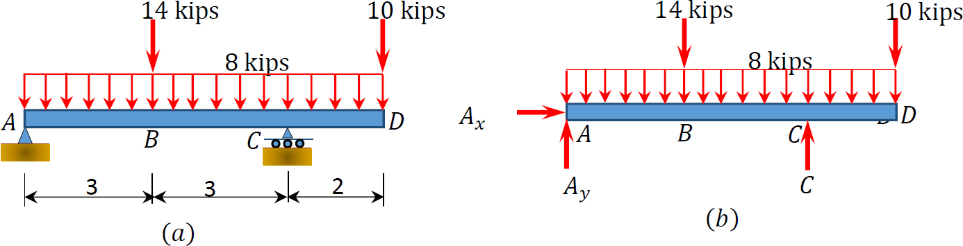
Beam Reactions and Diagrams - Strength of Materials ... Draw the beam free body diagram Replace the uniform distributed load (if any) with the equivalent point load Solve ΣM A = 0 (sum of moments about support A). This will give you R B (reaction at support B). Solve ΣM B = 0. This will give you R A. Using R A and R B found at steps 3 and 4 check if ΣV = 0 (sum of all vertical forces) is satisfied. Example 4 - Aerospace Engineering Free-Body Diagram of Beam:The beam is supported by a pin at point A and a horizontal roller at point D. Therefore, there are two unknown reactions at point A and one at point D as shown below. Notice that in drawing the free-body diagram we assume a direction for each reaction load. Solved Draw the free body diagram for the beam. A is a pin ... Mechanical Engineering questions and answers. Draw the free body diagram for the beam. A is a pin and B is a rocker. Draw the vectors starting at the black dots. The location and orientation of the vectors will be graded. The length of the vectors will not be graded. Question: Draw the free body diagram for the beam. Internal forces diagrams for the two-support beam Free-body diagram of the beam segments The free-body diagram of the beam section exposes internal forces acting at point B as external ones. The force component N B, acting along the axis x, is named the normal force. We skip normal force component calculation in the calculator since it allows only loads that act perpendicular to the beam.
What are Free Body Diagrams?
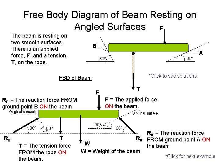
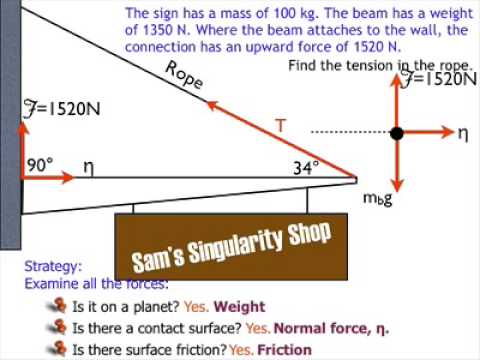
Extended Free Body Diagrams - mrwaynesclass.com Extended Free Body Diagrams BEAM forces Where beams attach to the wall there exists a pin hinge. The pin hinge exerts a reaction force. This force is broken down into two smaller forces we are calling the vertical force, "V" and a horizontal force "H." The vertical force, "V," keep the beam from sliding down the wall.
Simply supported beam diagrams : article | calcresource
Example 5 - Aerospace Engineering Free-Body Diagram of Beam:The beam is supported by a pin at point A and a link at B. We recognize the fact that link BE is a two-force member, thus the axial force in this member is along its axis or line BE. To simplify the calculations, RB can be broken into its rectangular components as shown below.
Shear force and Bending Moment diagram for cantilever
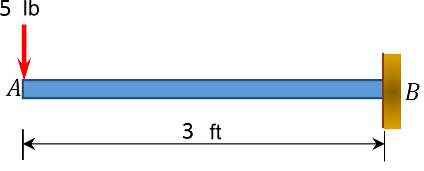
Lecture 23: Cantilever Free Body Diagram Example ... The video, then, displays a cantilever beam subjected to a point load of 20 N at free edge of the beam in downward direction. The length of the beam has given as 3 m. Next, using the given information, the video shows how to draw the FBD illustrating what reactions and momentum have been caused by the fixed support.
draw the free body diagram for the following problems a the beam in prob 5 25 b the crane and boom 2
What are Free Body Diagrams? - Massachusetts Institute of ... diagram (FBD). A free body diagram is a graphic, dematerialized, symbolic representation of the body (structure, element or segment of an element) in which all connecting "pieces" have been removed. A FBD is a convenient method to model the structure, structural element, or segment

Extended Free Body Diagrams
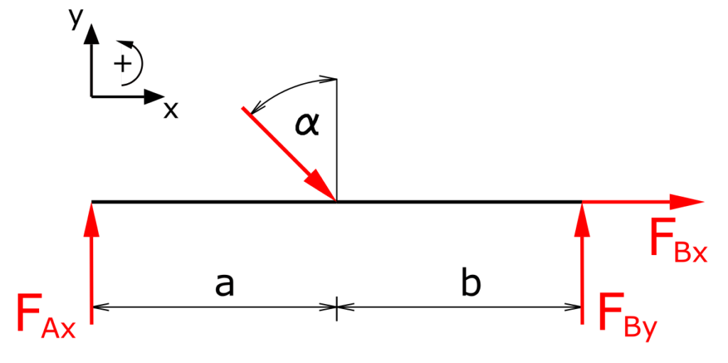
(a) Draw the free-body diagram of the beam. (b) Determine ... [latex]begin{aligned} sum F_{X}=0: & A_{X}+200 mathrm{~N}=0 \\ sum F_{Y}=0: & A_{Y}+300 mathrm{~N}-200 mathrm{~N}=0 \\ sum M_{A}=0:

Beam Free Body Diagram Calculator | Bending Moment and Shear ...
Solved Draw the free-body diagram for the beam. A is a ... Draw the free-body diagram for the beam. A is a rocker and B is a pin. Draw the vectors starting at the black dots. The location and orientation of the vectors will be graded. The length of the vectors will not be graded. Draw the free-body diagram for the; Question: Draw the free-body diagram for the beam. A is a rocker and B is a pin.
Free Body Diagram of CablePulley System C The
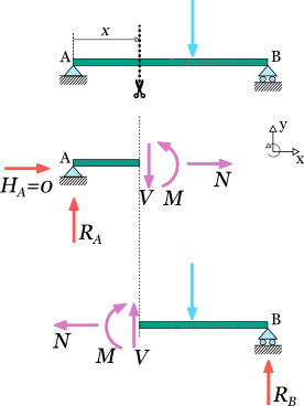
Free Body Diagram | PDF | Force | Beam (Structure) Hence the FREE BODY DIAGRAMS can also be called as EQUILIBRIUM DIAGRAMS, even though the former name is more popular. Finding the REACTION of beams for various types of APPLIED LOADS is a basic requirement in STATICS The above diagrams, which show the complete system of applied and reactive forces acting on a body, are called free body diagrams.
Draw the shear force diagram of beam, Mechanical Engineering
Q1: I have drawn the Free Body Diagram (FBD) of the ... To do so, cut the beam in those sections and draw the FBD of the cut section. Then use that FBD to write necessary equilibrium equations in order to solve for all the unknown internal loadings. P=100lbf 20 in; Question: Q1: I have drawn the Free Body Diagram (FBD) of the beam for you. Your task is to: a) Figure out internal loadings of the beam ...
Solved A) Draw a free-body diagram of the beam on paper. Use ...
Free body diagram of interior columns and associated beam ... The sections of beams are designed by assuming the distribution of the beam flexural strength along the building height, and consequently; the sections of columns are designed using the free-body ...

Shear Force Diagram - an overview | ScienceDirect Topics
Free Beam Calculator - Optimal Beam Free Beam Calculator for Statically Indeterminate Beams. Support Reactions. Shear Diagram. Moment Diagram. Indeterminate / Continuous Beams. Premium: Deflection and Stress Diagrams. Premium: Custom and Standard Sections or Materials. Premium: Save Unlimited Models and Sections. Premium: PDF Reports and Custom Logo.

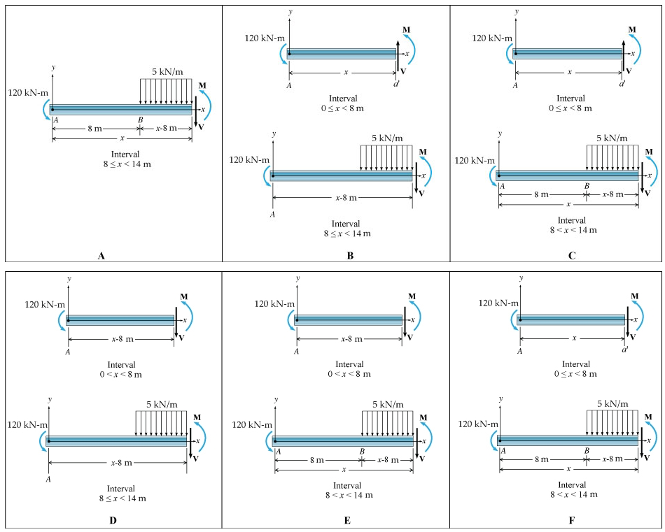
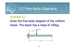
Ch4.1.pdf - 5.2 FREE-BODY DIAGRAMS 207 EXAMPLE 5.1 Draw the ...
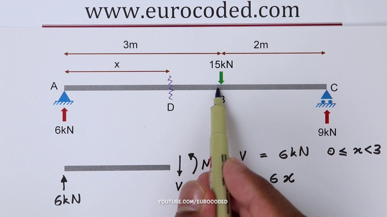
Statics: Free Body Diagrams - Engineering Statics Draw a neat, labeled, correct free-body diagram of the beam and identify the knowns and the unknowns. Solution. Begin by drawing a neat rectangle to represent the beam disconnected from its supports, then add all the known forces and couple-moments. Label the magnitudes of the loads and the known dimensions symbolically.
free body diagrams beam example solution
PDF Free Body Diagrams - Memphis 8 Free Body Diagrams Wednesday, October 3, 2012 ... right end of the beam and replace it by an x and a y reaction component F S W F PY F PX 44 Free Body Diagrams Wednesday, October 3, 2012 New Support Conditions Pin Connection ! The notation is clumsy here, we will try to be
Example 4
What is a Free-Body Diagram and How to Draw it (with ... A free-body diagram is a representation of an object with all the forces that act on it. The external environment (other objects, the floor on which the object sits, etc.), as well as the forces that the object exerts on other objects, are omitted in a free-body diagram. Below you can see an example of a free-body diagram:
1.4: Internal Forces in Beams and Frames - Engineering LibreTexts
Free body diagram for beam with pin-pin supports ... Download scientific diagram | Free body diagram for beam with pin-pin supports from publication: Requirements Analysis for Engineering Computation: A Systematic Approach for Improving Reliability ...

Free body diagram of the three segments of the cantilever ...

Statics eBook: Shear and Moment Diagrams I
Can you draw the shear force and bending moment diagrams of ...
6161103 5.2 free body diagrams
Mechanics of Materials: Bending – Normal Stress » Mechanics ...
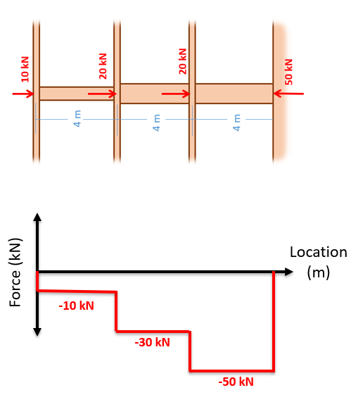
Mechanics Map - Axial Force Diagrams and Torque Diagrams
Shear Force And Bending diagrams - Roy Mech
How to Draw a Free Body Diagram - Simply Supported Beam with ...

Free body diagram for beam with pin-pin supports | Download ...

a) A cantilever under a concentrated load and (b) the free ...
6.2 Shear/Moment Diagrams – Engineering Mechanics: Statics
Bearing reactions under sloping load • Engineering Mechanics

A uniform beam of length 1 m and mass 20 kg is attached to a ...
1.4: Internal Forces in Beams and Frames - Engineering LibreTexts
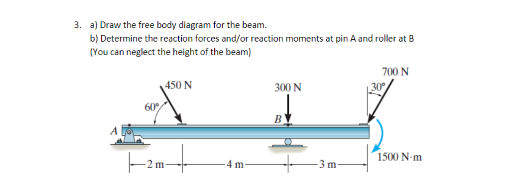
Solved a) Draw the free body diagram for the beam. b) | Chegg.com
Free Body Diagram for simply supported beam | Physics Forums

Free Body Diagrams
Untitled

Shear Force and Bending Moment Diagrams - Wikiversity
Mechanics Map - Axial Force Diagrams and Torque Diagrams
Simply supported beam diagrams : article | calcresource
Shear Force And Bending diagrams - Roy Mech

Free Body Diagram || Examples || Engineering Mechanics
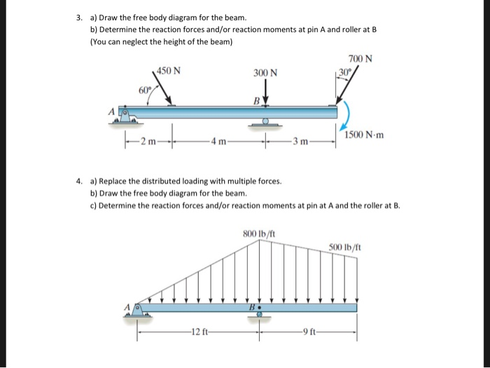
Solved a) Draw the free body diagram for the beam. b) | Chegg.com
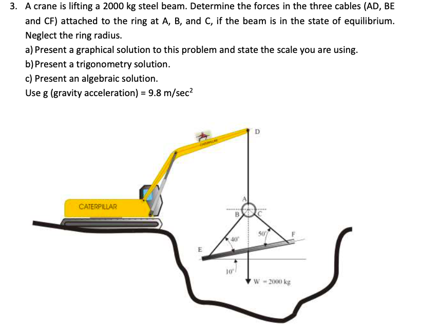
Crane lifting 2000-kg steel beam; find forces on each of 3 ...
Free body diagram - Wikipedia
0 Response to "40 free body diagram beam"
Post a Comment