42 fan coil unit diagram
HORIZONTAL FAN COIL UNITS MODEL SERIES: 40H (F, P, T, X) Engineered Comfort reserves the right to change any information concerning product or specification without notice or obligation. 7/23/13 EC-40HINST Page 1 of 4 Dimensions are in inches (mm). Safety Considerations The equipment covered by this manual is designed for safe and TECHNICAL SUPPORT MANUAL Fan Coils: FXM4X 2 496 04 5400 01 FAN COIL MODEL NUMBER IDENTIFICATION GUIDE F X M 4 X 1800 A T F = Fan Coil X = High efficiency ECM MOTOR TYPE M = Multiposition INSTALLATION TYPE 4 = Environmentally Sound R−410A REFRIGERANT X = TXV METERING DEVICE 1800 = 18,000 BTUH = 1½ tons
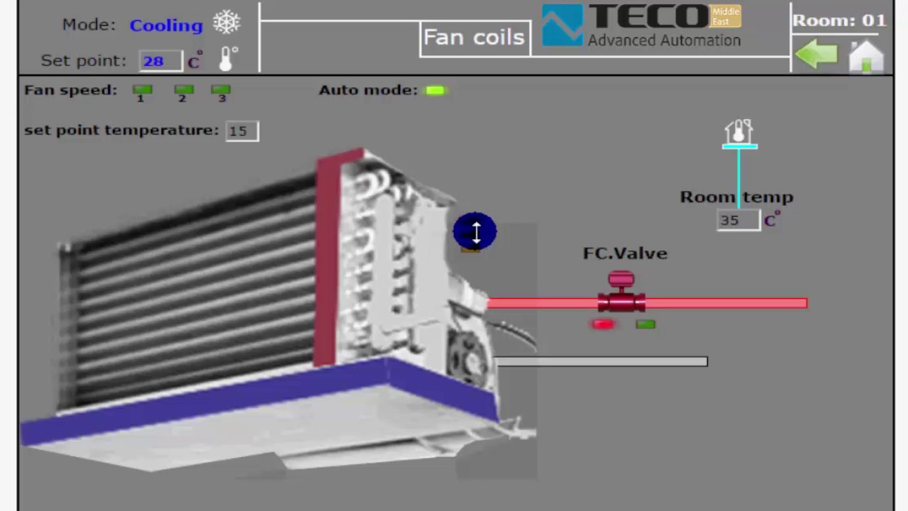
Fan coil unit thermostat wiring diagram. The individual switching differentials of the fan speed 1 2 3 q1 q2 and q3 can be adjusted via. T series invensys erie t155 data and instructions. Wiring diagram for carrier fan coil readingrat pertaining to fan coil unit schematic diagram image size 639 x 600 px and to view image details please click ...
Fan coil unit diagram
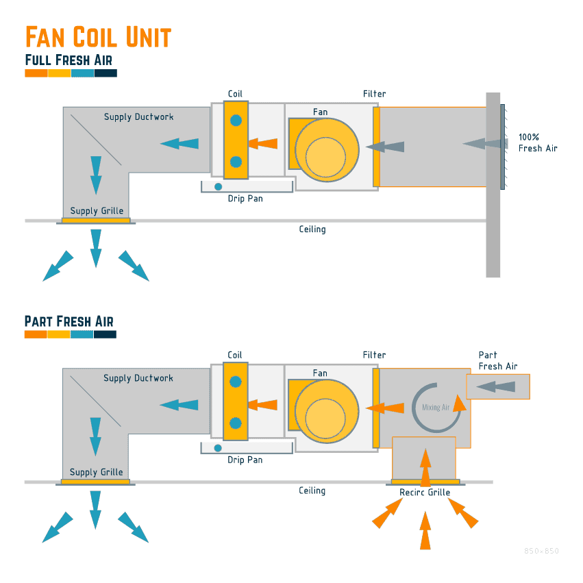
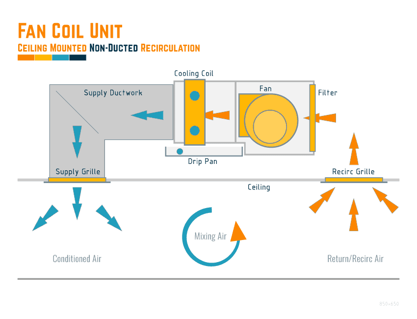
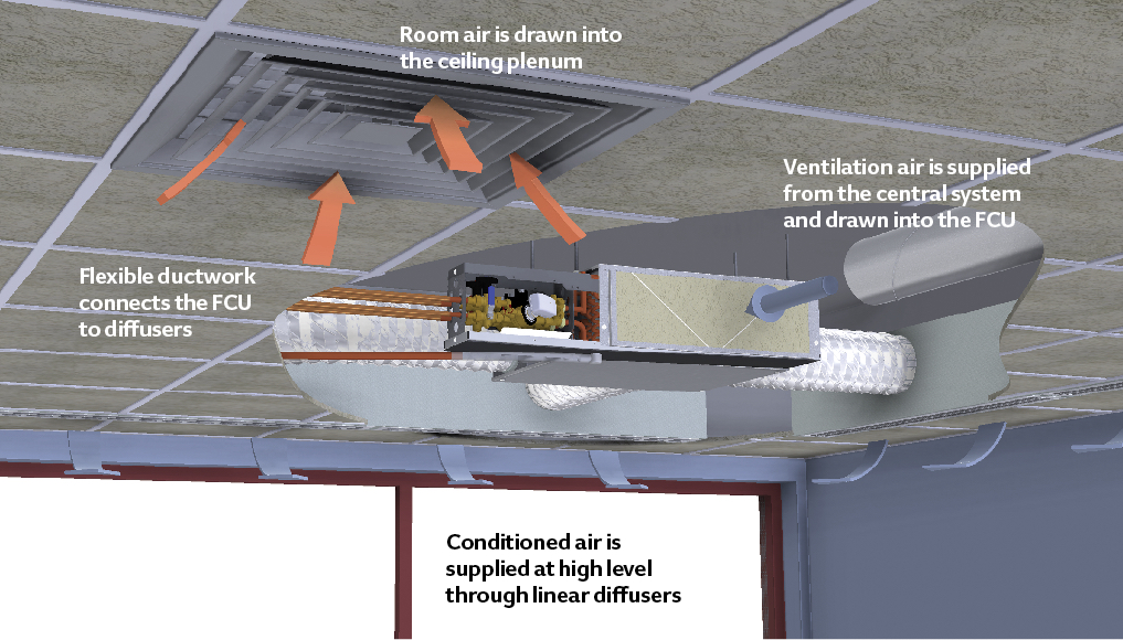
Figure I-GI-1. UniTrane fan-coil unit components. Vertical cabinet model is shown. General UniTrane fan-coil and Force Flo units are intended for single zone applications. These units have load capabilities of 200 to 1200 cfm. See Figure I-GI-1 for unit components. Fan-coil units are available as two-pipe, with or without electric heat Fan Coil Unit Diagram [Non-Ducted Recirculation] The below shows a typical fan coil unit that will use the ceiling as a return/recirculation plenum. *Note: there could be instances where a fresh air duct is connected to the unit to provide a minimal fresh air volume. This is usually a duct around 100mm in diameter. Jun 05, 2012 · It doesn’t help that I have high blood pressure in this heat. I am trying to save myself some money by figuring this out myself. I have the diagram of the unit which was inside the panel there are 3 wires: red, brown, and blue. According to diagram, brown is for the fan, blue is the herm and red is C. I haven’t screwed the panel cover back on.
Fan coil unit diagram. FCU. (fan Coil Unit ) Electric Wiring Diagram Related To #HVAC In Hindi\Urdu Air Cooled Chiller Working Linkhttps://www.youtube.com/watch?v=PzpItjxw7d0&t=28s... sound level of the unit compared to the previous range. Thanks to an EC motor and the ZN control's continuous and variable speed control, the FED fan coil can achieve exceptionally low sound levels without perceivable shifts of fan speeds. Ease of installation Thanks to its low height and its compactness, the unit can be installed in most false ... Fan Powered Air Terminal Unit Control Diagram: PDF. SD233600-04: Duct Connection - Air Terminal Units: PDF. SD233600-05: ... Heating Only Fan Coil Unit Controls: PDF. SD238200-03: Four Pipe Fan Coil Unit Controls: PDF. SD238200-04: Hot Water Cabinet Unit Controls: PDF. SD238200-05: Fan coil units are a highly efficient means of turning a water chiller or hot water boiler into an efficient, quiet air conditioning system. The units are super quiet because the only moving par t is the fan; making them ideal for use in offices, hotels and the home. The new range of fan coil units offers 5 models, of which 3 in flexible ...
5. A return fan may not be present on every unit if the supply fan creates enough of a draw to pull the air back through the system. Preheat System Components/Layout: Dampers Filters Cooling Coil Heating Coil Humidifier Supply Fan Return Fan Preheat Coils Air Flow: This system is a standard air handling unit that utilizes a preheat coil (H). Indoor air handler or blower unit for A/C or heat pump or furnace systems: How to inspect & repair the indoor components of air conditioners and heat pumps: the air conditioning system indoor air handler units, blower units, or AHU's, (also called fan coil units) including the air conditioner blower fan, the indoor cooling coil or "evaporator coil", air conditioning system … Automatic glow period control unit -J179-Radiator fan control unit -J293-Additional coolant pump relay -J496-Charge pressure control solenoid valve -N75-Activated charcoal filter solenoid valve 1 -N80-Camshaft control valve 1 -N205-Turbocharger air recirculation valve -N249-Intake manifold flap valve -N316-Valve for oil pressure control -N428-SB24 1) The outdoor unit, The outdoor unit, fitted outside the room, houses components like the compressor, condenser and expansion valve. 2) The indoor unit. The indoor unit comprises the evaporator or cooling coil and the cooling fan. The split air conditioner can be used to cool one or two rooms. OUTDOOR UNIT :
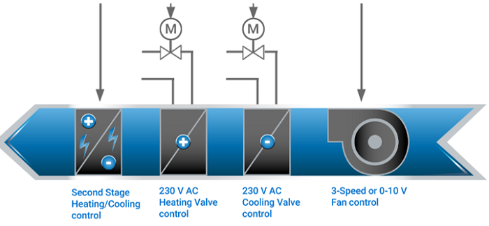
Fuse. Number. Fuse Name. Amps. Component or Circuit Protected. 1. H/L R HI. 10A. Passenger's MICU, Right Headlight (Connector B) 2. SMALL (EXTR) R. 10A. Taillight Relay (without Automatic Lighting), Passenger's MICU (Automatic Lighting), Right Front Parking Light (Latin America, Argentina), Right Front Side Marker Light (USA, Canada, Mexico), Right Front … INTERNATIONAL COMFORT HORIZONTAL FAN COIL UNIT WIRING DIAGRAM MANUAL [PDF] - Models FMC4, FMU4, WAMC, WATC, (2017) International Comfort Products, Lewisburg TN 37091 USA ICP International Comfort Products CONDENSING GAS FURNACE SERVICE MANUAL Model N9MSB (B Series) (2012) Models: N9MSB0401410B N9MSB0401712B N9MSB0601412B N9MSB0601716B ... A.The Fan Coil Unit is controlled by a unit mounted controller provided by Mechanical Systems Controls Contractor (MSCC). B.On a call for cooling, the thermostat signals for the heating control valve to modulate toward the closed position. On a further call for cooling, the thermostat signals for the fan to speed up from its Fuse box diagram (location and assignment of electrical fuses) for KIA Optima (TF; 2011, 2012, 2013, 2014, 2015).
CEILING MOUNT FAN COIL UNIT
Control unit with display for radio and navigation -J503-Voltage stabiliser (Only models with start/stop system) -J532-SB8: 30: Mechatronic unit for dual clutch gearbox -J743-SB9: 5: Steering column electronics control unit -J527-SB10: 20: Ignition coil 1 with output stage -N70-Ignition coil 2 with output stage -N 127-Ignition coil 3 with ...

Fan Coil Units - ProBalance from Crane Fluid Systems
Driver-side SAM control unit with fuse and relay module Rear SAM control unit with fuse and relay module: Valid for engine 629, 642, 646, 647, 648: CDI control unit Rear SAM control unit with fuse and relay module: 44: Valid for engine 646, 647, 648: CDI control unit: 15: Valid for engine 271, 272, 273: ME-SFI [ME] control unit
التØكم Ùˆ إدارة Fan coil units
Jun 05, 2012 · It doesn’t help that I have high blood pressure in this heat. I am trying to save myself some money by figuring this out myself. I have the diagram of the unit which was inside the panel there are 3 wires: red, brown, and blue. According to diagram, brown is for the fan, blue is the herm and red is C. I haven’t screwed the panel cover back on.
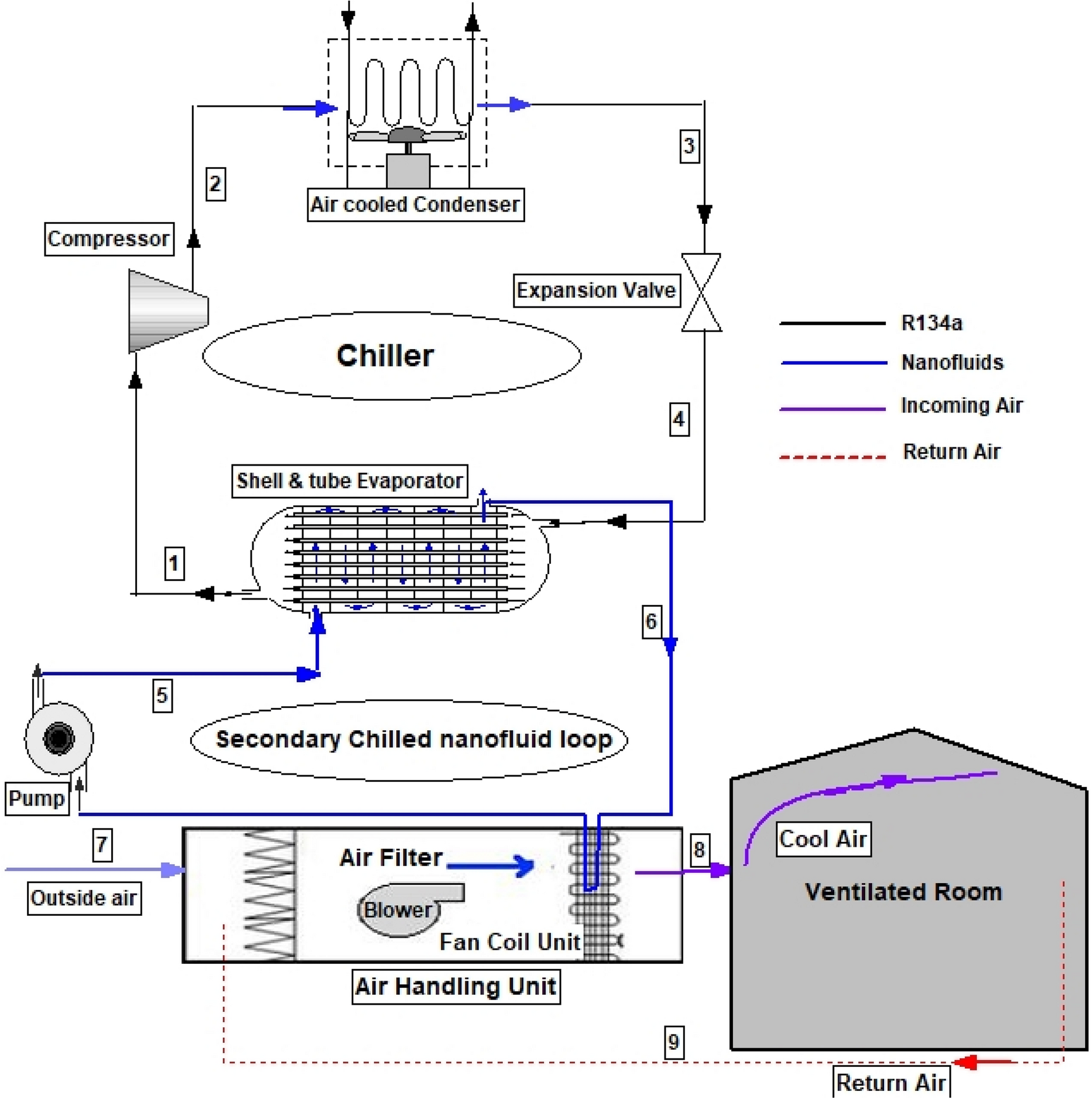
Parametric investigation of a chilled water district cooling ...
Fan Coil Unit Diagram [Non-Ducted Recirculation] The below shows a typical fan coil unit that will use the ceiling as a return/recirculation plenum. *Note: there could be instances where a fresh air duct is connected to the unit to provide a minimal fresh air volume. This is usually a duct around 100mm in diameter.

Thermostat for IEC Fan Coil Unit - DoItYourself.com Community ...
Figure I-GI-1. UniTrane fan-coil unit components. Vertical cabinet model is shown. General UniTrane fan-coil and Force Flo units are intended for single zone applications. These units have load capabilities of 200 to 1200 cfm. See Figure I-GI-1 for unit components. Fan-coil units are available as two-pipe, with or without electric heat
Fan-Coil Unit Coolers

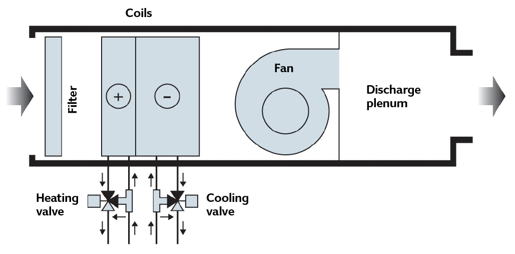
technical theory: Components of Fan-Coil Unit
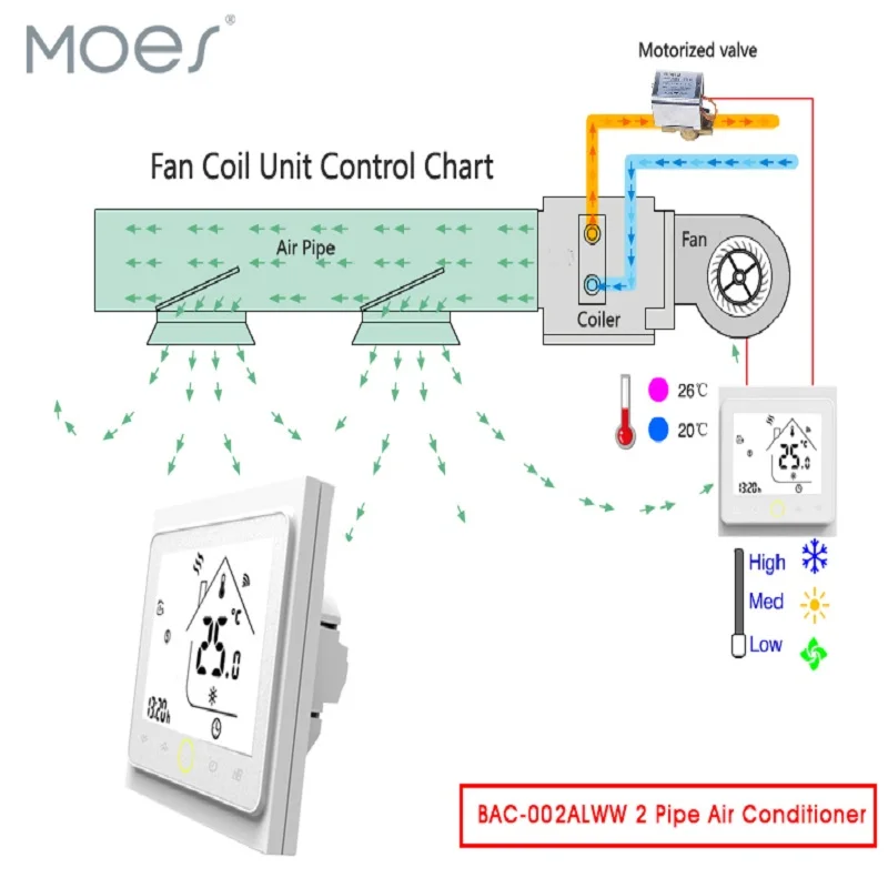
WiFi Central Air Conditioner Thermostat Temperature ...
Introduction to Fan Coil Units
![5: A fan coil unit(FCU) [11] | Download Scientific Diagram](https://www.researchgate.net/profile/Leonard-Peris/publication/330798539/figure/fig4/AS:721517260308482@1549034528563/A-fan-coil-unitFCU-11.png)
5: A fan coil unit(FCU) [11] | Download Scientific Diagram
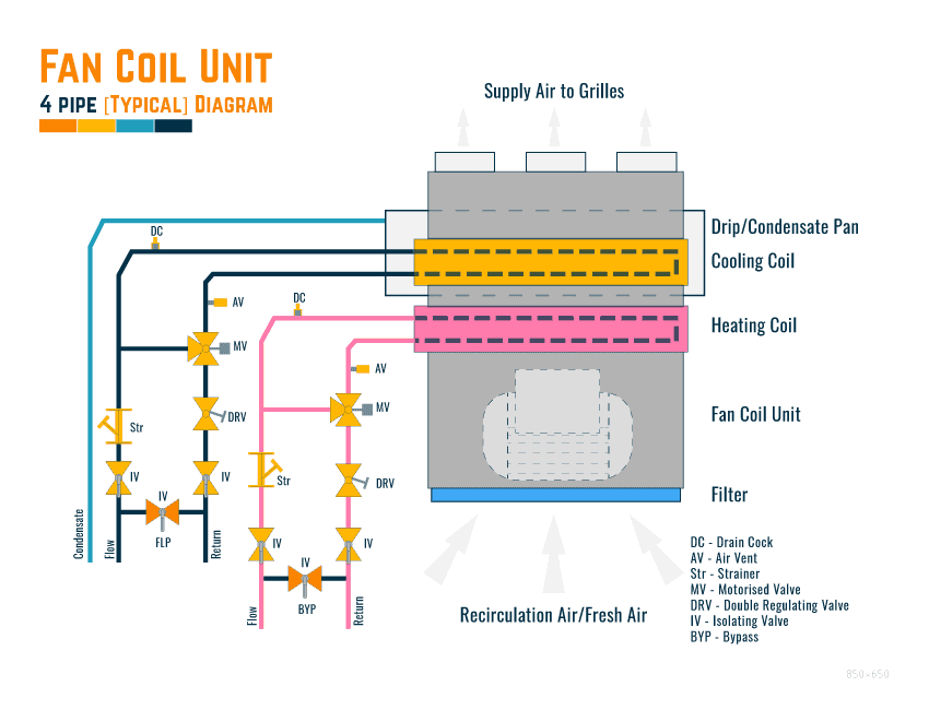
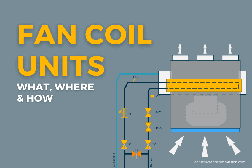
FAN COIL UNITS | What, Where & How - Constructandcommission.com

MEP WORK - Fan Coil Unit - FCU Hookup | Facebook
Riser Fan Coil - Category

Ceiling Air Ventilation And Wall Fan Coil Unit Diagram Stock ...
Wine Cellar cooling Systems

Ducted Fan Coil Unit (HVAC System) - China Fan Coil Unit, Air ...

Fan & Coil

Multi-Zone Fan Coil Unit Controller | rickardair

Room and zone control, Fan Coil Units (Excel 10 FCU)
Product Feature - Price Industries

A fan coil unit (FCU) is a simple device consisting of a ...

A schematic diagram of a fan coil unit. Readapted from [5 ...
New Fan Coil Piping Package

Fan & Coil
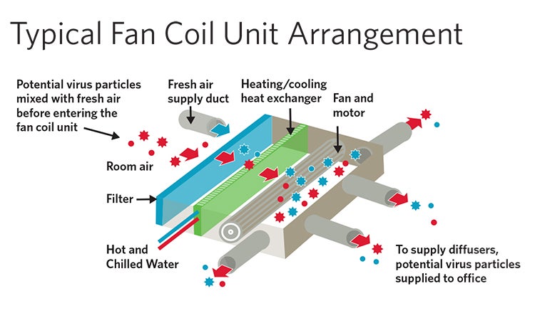
Specifying Fan Coil Units in a Post-COVID Environment | HDR

Fan & Coil

MLM Fan Coil Unit Controller Wiring Diagram | rickardair
Module 101: The evolution of fan coils for efficient ...
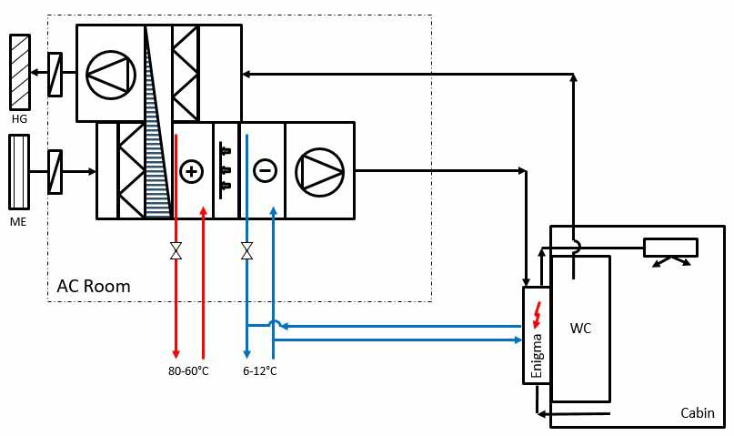
Fan Coil Systems (Enigma) Teknotherm Marine

Fan Coil - an overview | ScienceDirect Topics

11 Mechanical ideas | fan coil unit, piping and ...
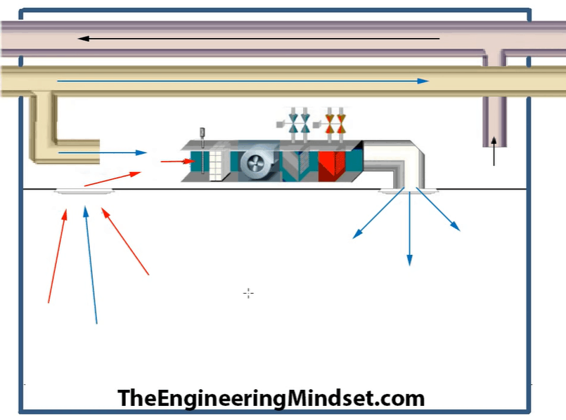
Fan Coil Units - FCU - The Engineering Mindset

Fan Coil Unit - an overview | ScienceDirect Topics
FAN COIL UNITS | What, Where & How - Constructandcommission.com
FAN COIL UNITS | What, Where & How - Constructandcommission.com
FAN COIL UNITS | What, Where & How - Constructandcommission.com

FAN COIL AIR CONDITIONING SYSTEM, A FAN COIL UNIT, AND A ...

Fan & Coil
2 Pipe versus a 4 Pipe System — Campus Housing

How It Works
Module 101: The evolution of fan coils for efficient ...
Fan Coil System - HVAC
0 Response to "42 fan coil unit diagram"
Post a Comment