41 ro booster pump installation diagram
The Booster Pump increases the feed water pressure to the membrane, while the Permeate Pump is located after the membrane and eliminates the performance robbing back pressure created by a full, or filling, air charged storage tank (see diagram # 2). Jan 07, 2022 · Reverse osmosis systems cost more if they boast an above-average number of filtration stages. In a typical reverse osmosis system, water flows through 4 stages: a pre-sediment filter, a carbon filter, a semi-permeable membrane and a post-filter. This type of system is capable of removing more than 99.9% of TDS (total dissolved solids) from ...
Easy to switch on/off thanks to a reliable pressure switch. . The Aquatec 8800 is one great water booster pump kit in the market and it's quite identical to the 6800 kit which is another best booster pump kit from Aquatec. The 8800 is designed to effectively raise water supply pressure and optimize the performance of an RO system.
Ro booster pump installation diagram
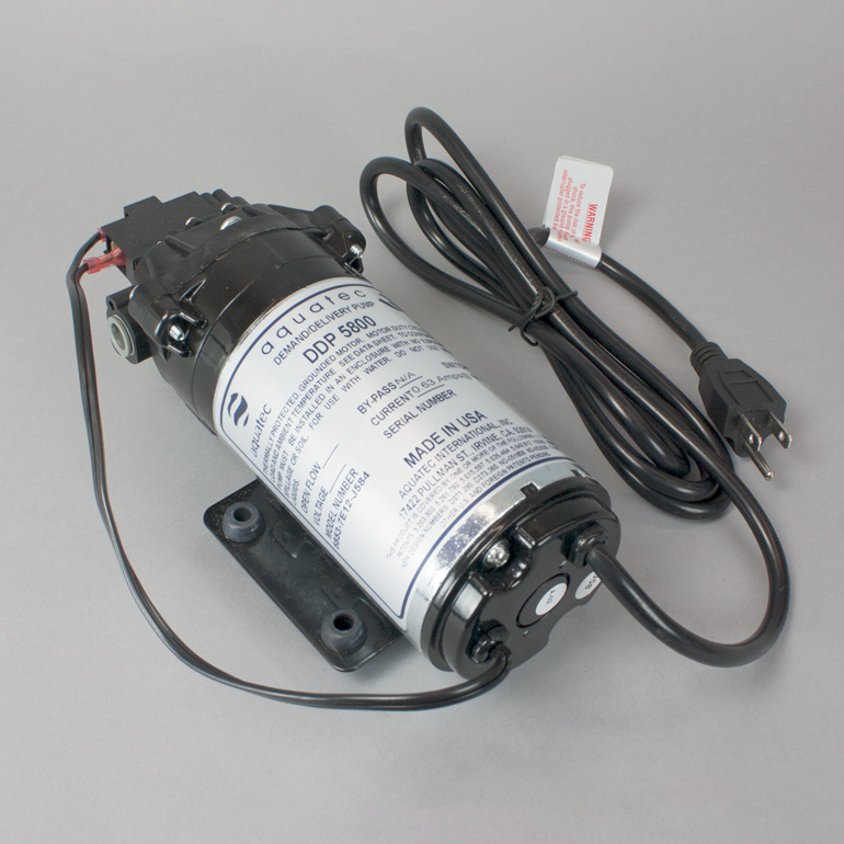
Permeate Pump decreases the time to fill the tank, but it does not reduce the amount of water produced. For manifold type RO systems, contact the factory for installation recommendations. Technical Specifications Part number: ERP 1000 Pump Type: Positive displacement, reciprocating, single action diaphragm, hydraulically driven Weight: 1 lb. Installation & Service Manual CounterTop Unit SW1 SW1C CT6000 . Installation & Service Manual Aquatec DDP5800 Pump. ... Flow Diagram- RO system with Booster Pump Installation. Electrical Diagram- #752 Booster Pump ESO TSO Transformer Connection. Jul 31, 2021 · Presenting Dr. Aquaguard™ range of water purifiers that brings together the goodness of Copper with Calcium, Magnesium and Zinc. Active Copper Maxx™ infuses Copper ions into the water. The Maxx effect releases not only Copper but right amount of other micronutrients like Calcium, Magnesium and Zinc.*
Ro booster pump installation diagram. In today's BRStv How-To episode, Randy is showing us how to install the Aquatech Booster Pump Kit to give your water pressure a boost for better filter effec... We like to mount the pump a few inches from the source water input into the RO system. Step 3. Using an RO Tube Cutter or a sharp razor blade cut your units RO tubing where you will want to splice in the booster pump and push the tubing into the head of the booster pump making sure to follow the flow direction arrow printed on the pump. Step 4. RO Booster Pump Diagram RO Permeate Pump Diagram RO Pressure Switch Diagram RO Drain Line Diagram Auto Shut Off Valve Diagram RO Check Valve Diagram RO Storage Tank Diagram RO Faucet Diagram Air Gap Faucet Diagram Non-Air Gap Faucet Diagram. Categories Reference Post navigation. Unpackage the booster pump and remove the rubber caps from the booster pump's quick connect ends Mount the booster pump in a dry place away from any heat sources. The booster pump can be mounted in any orientation, but the pump will operate the best with the pump mounted virtically, reducing air bubble traps captured in the head.
Regd.Address : 151/26 K, Molarband Extn., Badarpur, New Delhi - 110044; E-mail : info@sunshinetechnologies.in; Mobile : +91 9999839241,9999839341; Website : Jun 21, 2018 · Adding an electric booster pump increases the RO production rate, boosts the pressure tank storage volume, rejects more contaminants and increases faucet flow rate even if the reverse osmosis membrane pressure rating is met by the water supply. Residnetial RO systems work with diaphragm booster pumps that will typically increase the feed ... I have a BRS 4 Stage RODI unit, and just purchased a booster pump as I am on lower pressure well water. The instructions say to put the pump before the prefilters. I have read online stories about pumps cracking the clear acrylic canisters of the Sediment and Carbon prefilters and to place it right before the RO membrane. Diagram of a 4 stage Reverse Osmosis system with Booster Pump and Permeate Pump. Click on the PDF emblem and you will be transferred to the diagram. There is additional information on this web site for installation of the RO system. Click on Instruction Manuals and you can mouse down and locate the RO Installation Instructions.
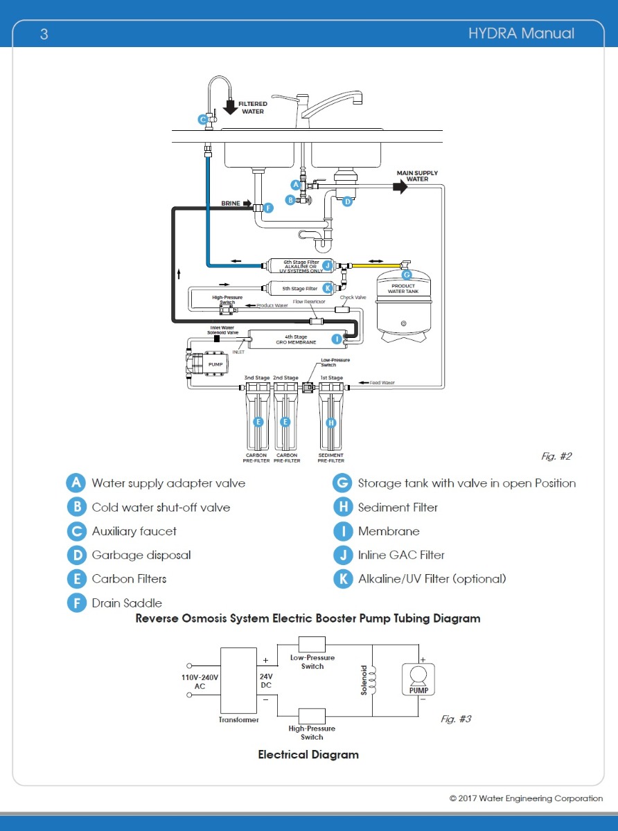
Booster Pump Installation Instructions 1. Install pressure switch in tank line. (See diagram on back for where to place the pressure switch). 2. Pump must be located within 2 feet of pressure switch and within 6 feet of power outlet. A. Pump can be mounted to the wall horizontally in either direction or vertically only one way ~ with pump head and Description The AQUATICLIFE RO Buddie +DI is a four-stage RO/DI unit designed for residential use to remove the Total Dissolved Solids (TDS) from tap water.... Academia.edu is a platform for academics to share research papers. Whole house ro system diagram. Because of the high levels of iron, a mangox iron filter is used first,. I need the standard 220v 60hz i need 220v. They worked well in that arena, as well. It produces water that is very low in tds, often with about a 95% reduction. Because purification of water is a way to enjoy healthy life.
black smartphone beside white plastic bottle and black smartphone
If input pressure is below 40 psi, a booster pump or a permeate pump is needed. We have a RO system with built-in permeate pumps, and we also carry booster pumps. If the input water pressure is above 80 psi ( you must use a pressure regulator to step down the pressure). We also carry small pressure regulators just for the RO system.

Clear RO 7 Stage - Inline DI - UV - Permeate Pump ...
Read the OPERATIONAL AND INSTALLATION GUIDELINES on the other side carefully before starting to install the pump. Consult the Factory if there is any question. 1. Determine the optimum location for your pump before proceeding. NOTE: Locate the pump after the sediment pre-filter and before the carbon pre-filter 9If part of R.O. system) 2.

boat floating in the sea during daytime
So, let's have a look at the parts of typical RO purifier: 1. In-let Valve. The inlet valve is the source of water for the RO system. Normally, the valve is set up on the cold water line. 2. Pre-Filter. Most of the ROs have a pre-filter as a guard to protect the membrane against salt, silt, and chlorine.

PurePro® Reverse Osmosis Diaphragm Booster Pump
* If input water pressure is below 0.3 kg/Sq.cm, use of booster pump attachment is recommended to increase input water pressure and proper functioning of the unit. Flow rate depends on the input water pressure and condition of the filters
Aquatec RO Booster Pumps by Pure Water Products – Pure ...
Booster Pump The Reverse Osmosis in line booster pump will increase the incoming water pressure after pre-turbidity and carbon filtration stages to 100psi for maximum efficiency and production quality through the Reverse Osmosis TFC membrane TDS removal process. Power standard outlet plug 110V / 60Hz is required. Faucet

Water Softener: Hague Water Softener Manual
Install the WECO FC-1400 reverse osmosis booster pump retrofit kit to boost your ro water pressure, get more water to the ice maker, reject more tds and fill up the tank faster. Kit works for standard and GRO reverse osmosis systems with capacity up to 50 gallons per day.
How RO Booster Pumps Work
1-800-955-8561. Mon - Fri • 9:00 AM - 5:30 PM ET. sales@h2odistributors.com.
Ro Booster Pump Installation Diagram - Free Wiring Diagram
Booster Pump Installation & troubleshooting guide The booster pump comes with the following components and works as follows: 1. The tap water runs thru an in-line sediment filter to keep dirty water from going into the pump. 2. Then thru an in-line check valve to stop any reverse pressure to the incoming PSI. 3.

28 Ro Booster Pump Installation Diagram - Free Wiring ...
An RO booster pump is used when the normal water pressure feeding an RO system needs to be increased or boosted. The efficiency of an RO booster pump depends on the incoming pressure of the feed water. The typical reverse osmosis system requires at least 50 psi feeding the system to function properly. If the water pres

Ro Booster Pump Installation Diagram - Atkinsjewelry
Commercial Reverse Osmosis Process: Skid mounted commercial reverse osmosis purifiers are tasked with purifying water from water sources such as lakes, rivers and wells. A commercial RO system utilizes a high pressure pump that pressurizes brackish or saline water against the surface of a semi-permeable membrane containing small pores.

Reverse Osmosis System w/ Booster Pump Installation Guide
Please like us on facebook https://www.facebook.com/reviewmaza/top 5 RO booster pumps.Support us by Buying anything on amazon : http://amzn.to/2sMGxsf via th...
Aquatec Demand Pump, 1.4 GPM - Pure Water Products, LLC
Kit For Converting Kinetico RO Systems Reverse Osmosis Membranes - Order this kit the first time you change to the new style of RO membrane. Includes membrane adaptor, ASV auto shut off valve and 1/4" hookup tubes. 13" of Blue and 9" of Green tube.

Ro Booster Pump Installation Diagram - Hanenhuusholli
REVERSE OSMOSIS MODULE - Module may be installed under sink or in any convenient location within 15 feet of source water supply and faucet. The 100V power outlet should be nearby to plug in the booster pump. STORAGE TANK - Tank may be placed in any space within 15 feet of faucet, generally under kitchen sink or in an adjacent unused cabinet.

Ro Booster Pump Installation Diagram - Free Wiring Diagram
RO system Instructions, Installation Manuals, & Support Articles. AR122 RO System Information & Diagram. AR125 RO System Information & Diagram. K5 RO System Information & Diagram. K6A RO System Information & Diagram. HK120 RO System Information & Diagram. SW1 SW1C CT6000 CounterTop System Information & Diagram.

Evolution-ROâ„¢ Pressure Booster Pump 110V
Open the ledge faucet and keep it open to relieve pressure. Position the pump so that the inlet tube — the 1/4 tube that supplies water to the RO unit — can be routed through it. Observe the directional arrows on the quick-connect fitting ports at the front of the pump, cut the inlet tube squarely and insert the ends into the appropriate ports.

35 4 Stage Reverse Osmosis System Diagram - Wiring Diagram ...
A. If your well pump can pump 12 gallons per minute, then you can use the 2.5 cubic foot model, which is recommended generally for larger homes of 2 to 4 bathrooms. For most homes with 1 to 3 bathrooms we recommend the 1.5 cubic foot size, which requires a …

34 Ro Booster Pump Installation Diagram - Wire Diagram ...
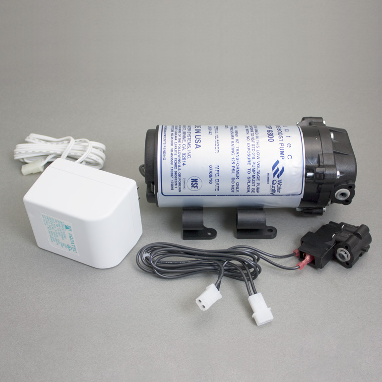
NSF 61 Certified. Made in the USA. The power cord and pressure switch for the pump are required components and sold separately. This Aquatec booster pump, model # CDP-6800 is used for low pressure applications for RO systems with membrane capacities up to 60 GPD. This pump uses a standard 110v electrical outlet.
Ro Booster Pump Installation Diagram - Free Wiring Diagram
34 Ro Booster Pump Installation Diagram - Wire Diagram Source Information. Zoeller Sump Pump Wiring Diagram - Wiring Diagram Schemas. Pumps & Pump Stations.
34 Ro Booster Pump Installation Diagram - Wire Diagram ...
560043 Booster Pump Kit Manual Installation Watts Premier has made it simple for you to walk through the installation of your new Booster Pump Kit. Find the instructions below and the diagram for your Reverse Osmosis System to guide you through the process. If you need any assistance you can contact us at 1-800-752-5
Replacement RO Booster Pump | Terry Love Plumbing Advice ...
To fix well water that smells bad, use one of these approaches: 1. Aerate water and/or inject air or oxygen. 2. Chlorinate well water to eliminate both sulfur and bacteria
Booster Pump Installation Diagram
Jul 31, 2021 · Presenting Dr. Aquaguard™ range of water purifiers that brings together the goodness of Copper with Calcium, Magnesium and Zinc. Active Copper Maxx™ infuses Copper ions into the water. The Maxx effect releases not only Copper but right amount of other micronutrients like Calcium, Magnesium and Zinc.*

Booster Pump Water Tank Installation Diagram - Water ...
Installation & Service Manual CounterTop Unit SW1 SW1C CT6000 . Installation & Service Manual Aquatec DDP5800 Pump. ... Flow Diagram- RO system with Booster Pump Installation. Electrical Diagram- #752 Booster Pump ESO TSO Transformer Connection.

34 Ro Booster Pump Installation Diagram - Wire Diagram ...
Permeate Pump decreases the time to fill the tank, but it does not reduce the amount of water produced. For manifold type RO systems, contact the factory for installation recommendations. Technical Specifications Part number: ERP 1000 Pump Type: Positive displacement, reciprocating, single action diaphragm, hydraulically driven Weight: 1 lb.

Reverse Osmosis 5 Stage + DI +Booster Pump + Permeate Pump ...

PurePro® RO103 Flow Diagram

blue and white building near green trees during daytime
![[DIAGRAM] Piping Diagram For Booster Pump](https://www.aquascience.net/media/catalog/product/d/a/davey-install-diagram_8.gif)
[DIAGRAM] Piping Diagram For Booster Pump

Hanging Type 6-Stage Big Pressure Gauge RO Filter System ...
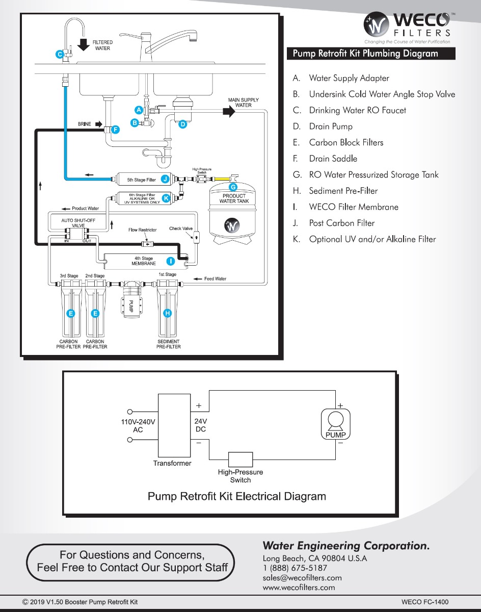
Installing FC-1400 RO Booster Pump Retrofit Kit - Video

Reverse Osmosis 5 Stage + DI +Booster Pump + Permeate Pump ...

How a Permeate Pump Works with a Reverse Osmosis System ...

34 Ro Booster Pump Installation Diagram - Wire Diagram ...

woman in brown jacket standing near trees during daytime

34 Ro Booster Pump Installation Diagram - Wire Diagram ...

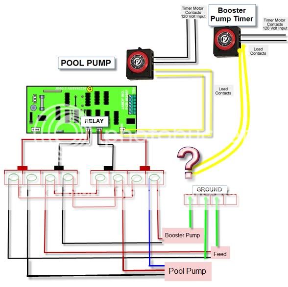
RO Electrical Connection Diagram - YouTube

34 Ro Booster Pump Installation Diagram - Wire Diagram ...

Water Booster Pump Installation Diagram

grayscale photography of man driving vehicle

50GPD RO System with Booster Pump - Osmotech (Pty) Ltd

34 Ro Booster Pump Installation Diagram - Wire Diagram ...

32 Water Pressure Tank Installation Diagram - Wiring ...
0 Response to "41 ro booster pump installation diagram"
Post a Comment