40 single phase to three phase converter circuit diagram
The voltage between two phases in a three phase power supply is 415V while that between a phase and the neutral is 240V. Hence, you can provide three single phase supplies using a three phase supply (this is how it is normally done for residential and small business loads). The connection diagram on the left shows how a deltadelta connection can be made either with three single-phase transformers or with one three-phase transformer. The diagram offers visual representation of an electrical. Pin On Power Transformers With this sort of an illustrative guide you are. 3 phase transformer wiring diagram. 3 phase transformer wiring diagram […]
Here are a number of highest rated Single To Three Phase Converter pictures upon internet. We identified it from reliable source. Its submitted by executive in the best field. We take this kind of Single To Three Phase Converter graphic could possibly be the most trending subject in the same way as we share it in google benefit or facebook.

Single phase to three phase converter circuit diagram
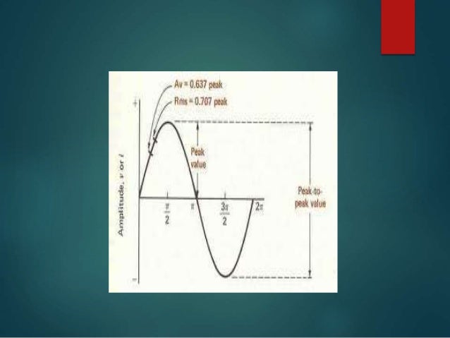
Typical single-phase to 3-phase static converters from American. Rotary Phase Converters (left) and Phase-A-Matic (right). Figure 1. Schematic of 3-phase ...5 pages Single Phase Motor Wiring Diagram With Capacitor - baldor single phase motor wiring diagram with capacitor, single phase fan motor wiring diagram with capacitor, single phase motor connection diagram with capacitor, Every electrical arrangement is made up of various unique pieces. Each component ought to be placed and linked to different parts in particular manner. SINGLE-LINE OR ONE-LINE DIAGRAM Electrical Power System. The balanced three-phase system is understood through the use of a single-phase resultant system that consists of any one line of three phase system and one neutral as returning path. It is generally one line is drawn to have an understanding of single-phase system.
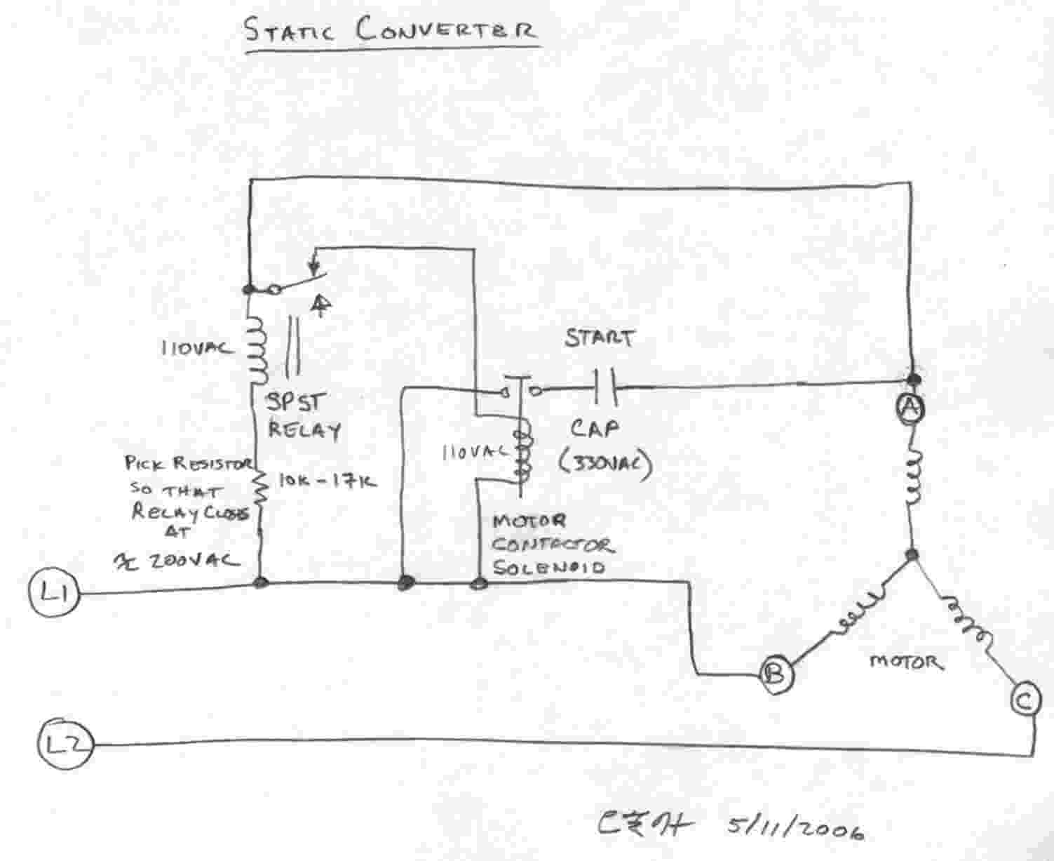
Single phase to three phase converter circuit diagram. I am trying to make a circuit for single phase to single-phase cyclo converter. Using Pic Micro Controller for Triggering Gate of Trails. Triac -> Optocoupler -> For Trigring Triacs -> PIC Micro controller. I was unable to find any circuit diagram with the Triac Driver part. After some experiments I found a method to trigger Triacs. Hi, the 4035 circuit is a single phase frequency to 3 phase frequency converter circuit which I got from internet after some searching, I am not sure regarding its working principle, you may have to consult its datasheet for the details, or try some other design which can replicate its function for this project. Pin#1, 23, 24 = 3-Phase sequential signal from the BLDC single ended Hall sensor can be configured with these pinouts, if the BLDC is a sensorless, you can feed an external 3-phase 120 degree apar input on these pinout at +5V level. Parts List for the above discussed 50V 3-phase BLDC motor driver circuit. C1 = 100 µF; C2 = 100 nF; C3 = 220 nF The capacity of single-phase inverter circuit is generally below 10kVA due to the limitation of the capacity of the power switching device, the current of the neutral line (neutral line), the load balance requirements of the power grid and the nature of the electrical load. Most of the large-capacity inverter circuits are in the form of three ...
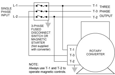
I am feeding a 3 phase sub-panel with T1, T2, and T3 from my American Rotary AD20. Wiring 1 machine at a time directly to the phase converter works just fine but when I wire the phase converter to the 3-phase panel and turn on the breakers, the start/stop switch on my 3hp grinder is buzzing, with the phase converter OFF. The below wiring diagram shows how we would assemble a complete motor starter with a start stop button for a single phase motor utilizing a 3 pole contactor. 3 phase star delta motor wiring diagram earth bondhon thermal overload relay wiring diagram and reset adjustment instructions wiring a single phase motor through 3 contactor how and why A diagram of a single-phase 120240V service. In the US 120 240V 1 Phase 3 Wire is the standard for homes and 240V 3 Phase Open Delta is the standard for small buildings with large loads. The following wiring diagram shows the installation of a 60A subpanel for both 120V and 240V. It includes instructions and diagrams for various types of wiring ... To convert 3-phase to single-phase power, you can use a phase converter. This device can be wired to the motor you plan to run that requires single-phase power. Note that this will impact only the device wired to it, not an entire outlet because it is not hardwired into your electrical system. Run two wires from the motor to the converter.
Single Phase Motor Starter With Timer. Generally a single phase timer is used for a 3phase starter with automatic star —delta function for a star —delta induction motor of 3phase, at a voltage of 415 volts, and timer voltage will be 240volts. Unique wiring diagram for single phase dol starter well. 240 Volt Single Phase Wiring Diagram - 220 volt single phase motor wiring diagram, 220 volt single phase wiring diagram, 240 volt single phase motor wiring diagram, Every electric arrangement is composed of various unique components. Each component ought to be placed and connected with other parts in particular way. Otherwise, the arrangement won't work as it should be. Three-phase power is a three-wire ac power circuit with each phase ac signal 120 electrical degrees apart. Residential homes are usually served by a single-phase power supply, while commercial and industrial facilities usually use a three-phase supply. The post discuses a 3 phase inverter driver circuit which can be used in conjunction with any ordinary single phase square wave inverter circuit. The concept is basically the same, I have just changed the 3 phase generator stage for the application. There are four switches. In the single phase motor, the secondary winding phase advance 90° than the main winding, thus making the motor to form ...

Three-Phase to Single-Phase Transformer - CR4 Discussion ...
Single-Phase Full Converter: Single-Phase Full Converter converts the AC signal to DC signal and utilizes thyristor only. The utilization of thyristor only for the conversion process makes it fully controllable and provides wider control over the level of DC output voltage.. In this section, we will discuss the operation of a single-phase full converter along with its circuit diagram, waveform ...
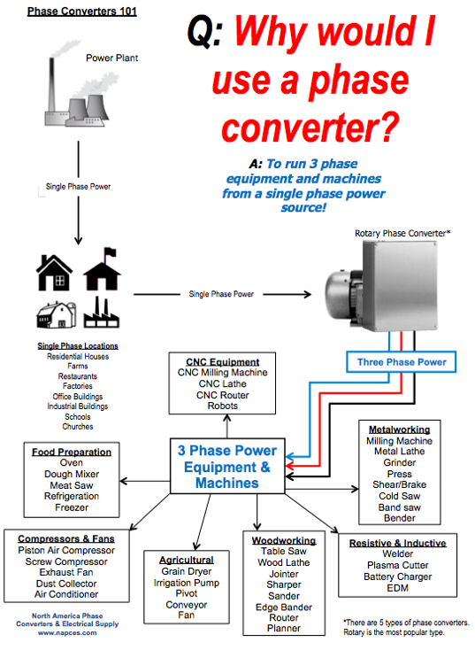
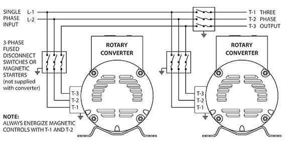
Rotary & Static Phase Converter FAQs - NAPCco
The output of the inverter is given to the load. III.CIRCUIT DIAGRAM. Page 3. ISSN (Print) : 2320 – 3765. ISSN ...7 pages

3 Phase Rotary Converter Wiring Diagram Download
The Single phase to Three phase converter using MOSFET, or IGBT with PWM for driving three-phase induction motor by using switching ...May 27, 2013 · Uploaded by MK Subramanian

Make this 3 Phase Inverter Circuit
Change single phase to 3 phase. A metastable polymorph which forms rapidly due to lower surface energy will transform to an equilibrium phase given. The power that enters a data center is usually 3 phase AC power which means 3 phase alternating current power. The curves on the phase diagram show the points where the free energy and.
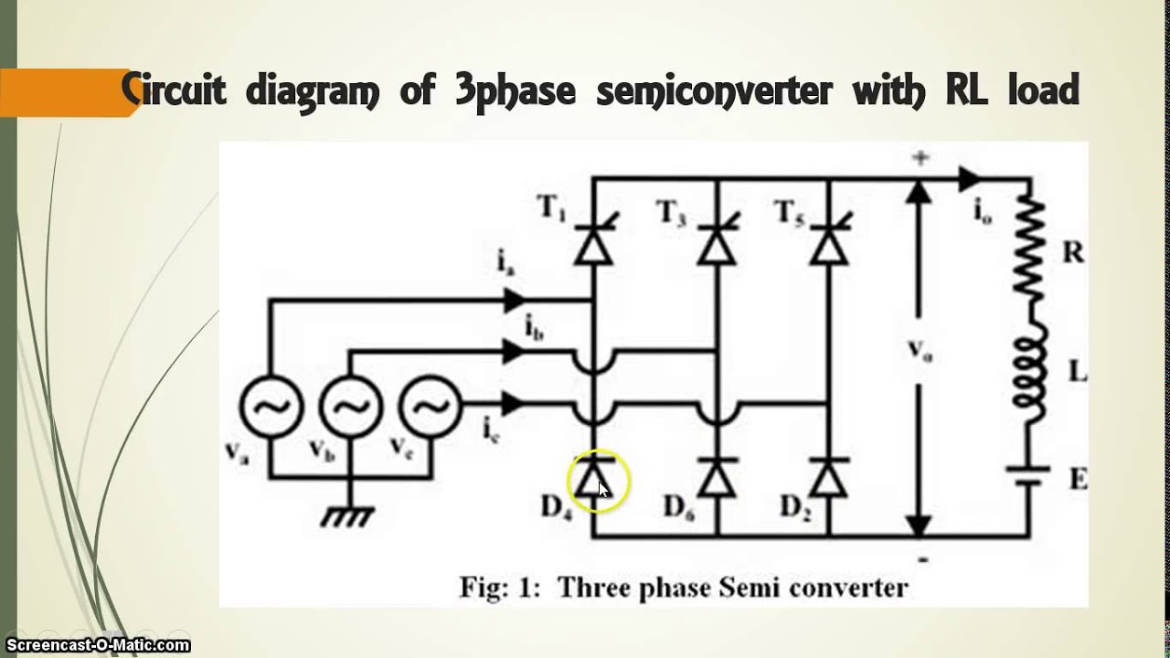
three phase semi-converter with RL load - YouTube
A three phase motor must be wired based on the diagram on the faceplate. Phase wiring diagram today wiring diagram 3 phase to single phase wiring diagram wiring diagram contains several comprehensive illustrations that display the link of assorted products. Product connect a jumper between the h2 and h3 terminals and bring the v in on h1 h4.

Ask the Renewable Energy Guru: Three Phase Motor as Single ...
Complete Phase Power Failure Protection. • Built in protection protects the rotary phase converter and your equipment in the event of a power loss. • During a black out, the Pro-Line Rotary Phase Converter shuts down all 3 legs of power. • Some brands only shut down the generated leg and can cause single phasing when power resumes.
PANEL OF THREE PHASE METER CONNECTIN IN HINDI (Hindi/Urdu ...
The diagram indicates that three-phase current source inverter. In this circuitry, the 6 SCRs are linked in this sequence SCR1, SCR6, SCR2, SCR4 SCR3 SCR5, and capacitors from C1 to C6 offer the commutation needed through SCR.
Bridge Rectifier : Circuit Diagram, Types, Working & Its ...
A 240-volt single phase wiring uses two hot wires. If not, the arrangement will not function as it ought to be. 480V Single Phase Wiring Diagram 480 Volt Single Phase Transformer with 480V 3 Phase Wiring Diagram, image size 472 X 264 px, image source : The MCCB used here is a 3 Pole ,60A unit. Your present wiring can deal with the three-phase ...

Circuit diagram of the single-phase full-bridge NPC ...
L1 and l2 are designated as the two connection points representing the two electricity flow path inherent with single phase circuits where a single phase supply voltage is fed to the motors internal circuit. 0.18kw to 3.0kw (capacitor start / capacitor run) output: Wiring diagram will come with numerous easy to follow wiring diagram directions.

Phoenix Phase Converter Wiring Diagram Collection
How To Use Three Phase Motor In Single Power Supply Electrical Engineering Centre. Pdf A Simple Method For Operating The Delta Connection Standard Of 3 Phase Induction Motor On Single Supply. Forward Re Verse Control Developing A Wiring Diagram And Reversing Single Phase Split Motors Electric Equipment.

Ronk Phase Converter Wiring Diagram | Free Wiring Diagram
With three 208V circuits it is clear that a substantial amount of power can be deployed in one three-phase PDU. To calculate the apparent power of a three-phase power feed the calculation is volts x amps x the square root of 3 which is 1.732. A three-phase 208V, 20A feed is 7205VA or 7.2kVA (208V x 20A x 1.732).
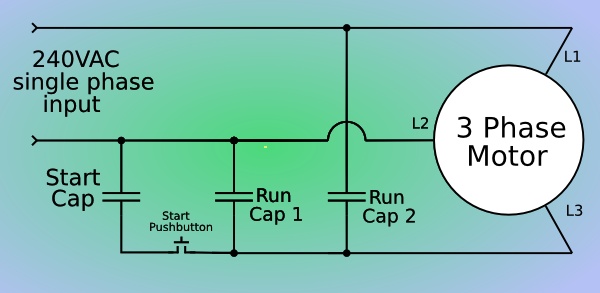
Single Phase to Three Phase Converter
SINGLE-LINE OR ONE-LINE DIAGRAM Electrical Power System. The balanced three-phase system is understood through the use of a single-phase resultant system that consists of any one line of three phase system and one neutral as returning path. It is generally one line is drawn to have an understanding of single-phase system.
Question about single phase to three phase conversion ...
Single Phase Motor Wiring Diagram With Capacitor - baldor single phase motor wiring diagram with capacitor, single phase fan motor wiring diagram with capacitor, single phase motor connection diagram with capacitor, Every electrical arrangement is made up of various unique pieces. Each component ought to be placed and linked to different parts in particular manner.

Guide to be an Electronic Circuit & Design Engineer ...
Typical single-phase to 3-phase static converters from American. Rotary Phase Converters (left) and Phase-A-Matic (right). Figure 1. Schematic of 3-phase ...5 pages
Single Phase To Three Phase Converter Circuit Diagram ...

LTC3829 3-Phase, Single Output Synchronous Step-Down DC/DC ...

Single Phase to 3 Three Phase Converter Circuit Diagram

Image from page 530 of "The Street railway journal" (1884)
Single Phase to 3 Three Phase Converter Circuit Diagram

Figure 1 from Startup procedure for three-phase three-wire ...

The Manchester (e,2e) Experimental Hardware page prepared ...

Phoenix Phase Converter

Rotary Phase Converter Wiring Diagram — UNTPIKAPPS

Brushless DC Motor Driver Circuit Diagram | Schematics World

30 HP Rotary Phase Converter Panel CNC Rated | eBay
35 How To Convert Single Phase To Three Phase Circuit ...
3-phase motor static phase converter - bolis.com

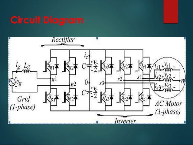
Configuration of the proposed single-phase to three-phase ...
3 Phase Converter Wiring Diagrams - technolasopa

Three-phase inverter circuit. | Download Scientific Diagram

Subpanel / RPC panel / 3 Phase Load Center Wiring

THREE-PHASE DUAL CONVERTER - Power, Electronic Systems ...
3-Phase Converters

(PDF) STATIC PHASE CONVERTERS, AN OPTION TO RURAL ...

28 Single Phase To Three Phase Converter Circuit Diagram ...

Single-phase to three-phase matrix converter with ...

Ronk Phase Converter Wiring Diagram | Free Wiring Diagram

Rotary Phase Converter Help and Troubleshooting
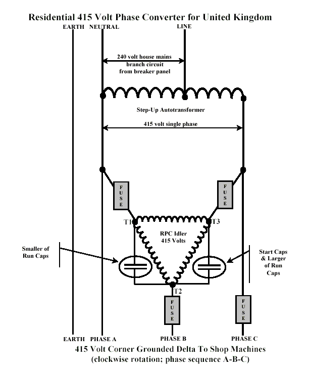
Homemade Rotary Converter 230v Single Phase to 415v Three ...

How to Build an Auto-Start Rotary Three Phase Converter ...
0 Response to "40 single phase to three phase converter circuit diagram"
Post a Comment