37 preamp to amp connection diagram
The current drain of the pre-amp is less than 50 mA, so many 12 V unregulated supplies may be adequate if you have one. Replace D1 with a wire link if necessary, making sure you have the supply polarity correct! If you are using a 15-20V supply for your power amplifier, you can use that as your pre-amp supply as well. A wiring diagram is a streamlined standard pictorial representation of an electric circuit. This is the resistance (impedance) presented by the speakers that is seen by the amplifier. Super Simple 3 Watt Audio Power Amplifier Here is the circuit diagram of superb mini audio power amplifier, That can be power with 4.5 volt dc to….
Wiring speakers in parallel is simple. Connect the + terminal on the amp to the + terminal on each speaker. Then do the same for the - terminals. An example of this is shown below. For two 4 ohm speakers, the total impedance would be 2 ohms. To find the total impedance of speakers in parallel, use the formula below.

Preamp to amp connection diagram
Subwoofer Wiring Diagrams. Step #1 - Choose the # of subwoofers you will wire in your system from one amplifier output. Step #2 - Specify 2 or 4 ohm single voice coil OR 2 or 4 ohm dual voice coil subwoofer (s) The Subwoofer Wiring Diagram tool will then display two wiring options with the final impedance at the amplifier. To connect an integrated amplifier to an AV receiver using RCA Cables, find the pre-out section on the AV receiver and connect to the Left and Right channels. Then, connect these to the Integrated Amplifier, and finally, plug in your speaker wire to the Integrated Amp to achieve sound. While there are several different routes that you could ... Sep 3, 2021 — The circuit diagram can be seen below. The circuit is self explanatory, and can be integrated with any standard power amp for further ...
Preamp to amp connection diagram. Title: Practical Amplifier Diagrams Author: Jack Robin, Chester E. Lipman Subject: Audio amplifier schematics Keywords: Audio amplifier schematics Oct 17, 2021 · That’s it for the connection. That’s all you need to do for bridging your subwoofer with a 2-channel amplifier. 2-channel amp wiring diagram. You can understand the whole concept better with this wiring diagram of a 2-channel amp to a single subwoofer. Sonos Connect:Amp, power cord, flat Ethernet cable, Sonos QuickStart Guide, and Legal/Warranty information. Exclusive Price: $ Sonos System Wiring Diagram If you are adding this CONNECT:AMP to an existing Sonos system, you can Use high-quality speaker wire to connect the right speaker to the CONNECT:AMP. Home Theater Setup Diagram. Wiring Diagrams. Masthead Amplifier Wiring Diagram. 2 year guarantee eu declaration of conformity uhf masthead amplifiers instruction manual insallation instructions variable gain installation how to properly install a pre amplifier the solid signal blog mar 6 vhf wide band circuit design electronic project vision psu which wire goes where avforums fm dab ...
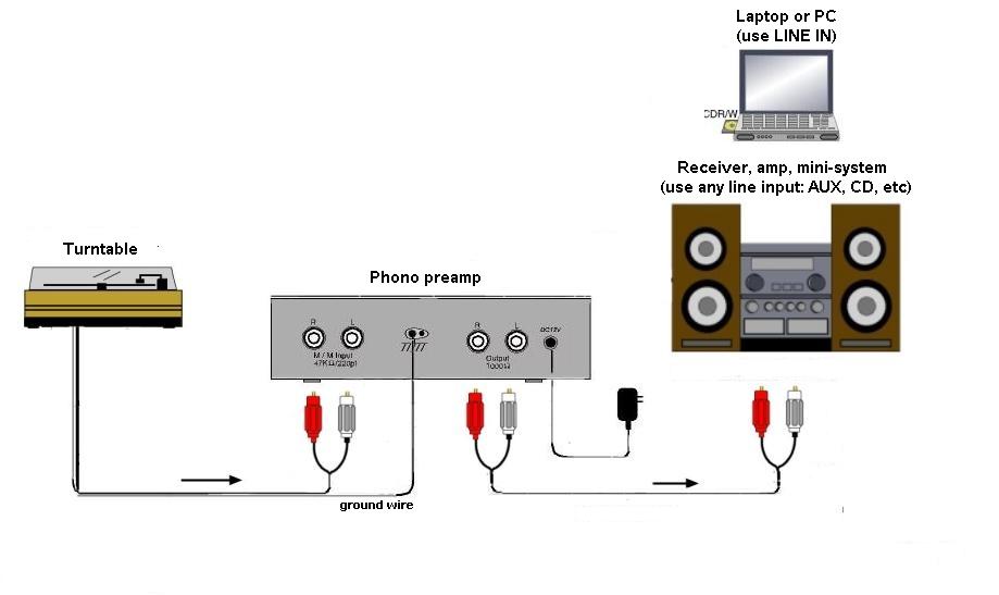
Mini Cooper Wiring with Harman Kardon Amp Search Wiring Diagrams DSP & Amps by JBL MS series ~ Midrange & Tweeters by HAT Legatia ~ Midbass & Subs by SI. If you want to bypass the h/K you can use his wiring information. I dont need it cause the head unit has a built in amplifier. installer before I got my first MINI, and i had to relearn ... Inverting Amplifier Circuit Diagram The output signal that is generated due to this amplifier is that will be of angle 180 degrees out-of-phase in comparison to the applied input signal. In this kind of amplifier the output is exactly in phase to input. The phase shift is 0. Rf and Rin together. Vins Vout Figure 4. Step 5. Connect the source equipment to the preamplifier's input plug-ins, and connect the speakers to the power amplifier's output plug-ins. Choose your cable type carefully. XLR cables offer better sound quality than RCA cables, but not all equipment is compatible with XLR cables. Preamps also are the signal distribution centers, connecting to external amplification. ... Access the rear of the sources, preamp and amplifier(s).
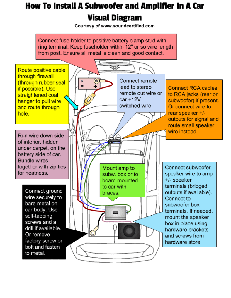
What factors do we look for in the specifications of preamps and power amps to make sure we have the perfect match. Paul gives us a quick tour of the challen... The preamp has a set of amp output connector posts: red and white, green and black. The red and white ones are marked "right side", the green and black are marked "left side". Also there is a "C" marked on the white one and on the black one. I assume these are the ones that will connect to the amplifier. Connect the power wires from the amp to the battery. Run the wires under the glove box and grommet. Install a fuse box on the wire and attach the wire from the battery and subwoofer. After that, start the engine and see how it works. Filed Under: Car Tagged With: Install A Car Amplifier. Check out our amplifier wiring diagram to see how the wiring gets connected in a typical 2-amp system. Step 5 — Connect the power wire Attach the power cable to the positive battery terminal (not directly to the battery post itself).
100W Mosfet Power Amplifier Circuit Image - Home Wiring ...
In this way, left channel of amplifier is connected with two speakers in series. Repeat the process for the right channel and connect two speakers. So, all the four speakers will get connected in series with 2 channel amplifier. Series wiring is our first method to connect 4 speakers to a 2 channel amp. The next method is parallel wiring.

100W Subwoofer Amplifier Circuit | audio wiring diagram
Capacitors aren't usually necessary in a car stereo installation but we included one here to show how it would get wired into a system. Amplifier Wiring Diagram ...
2 Channel Amp Wiring Diagram | Cadician's Blog
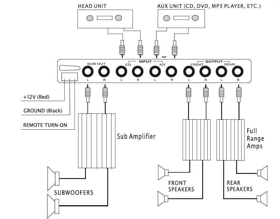
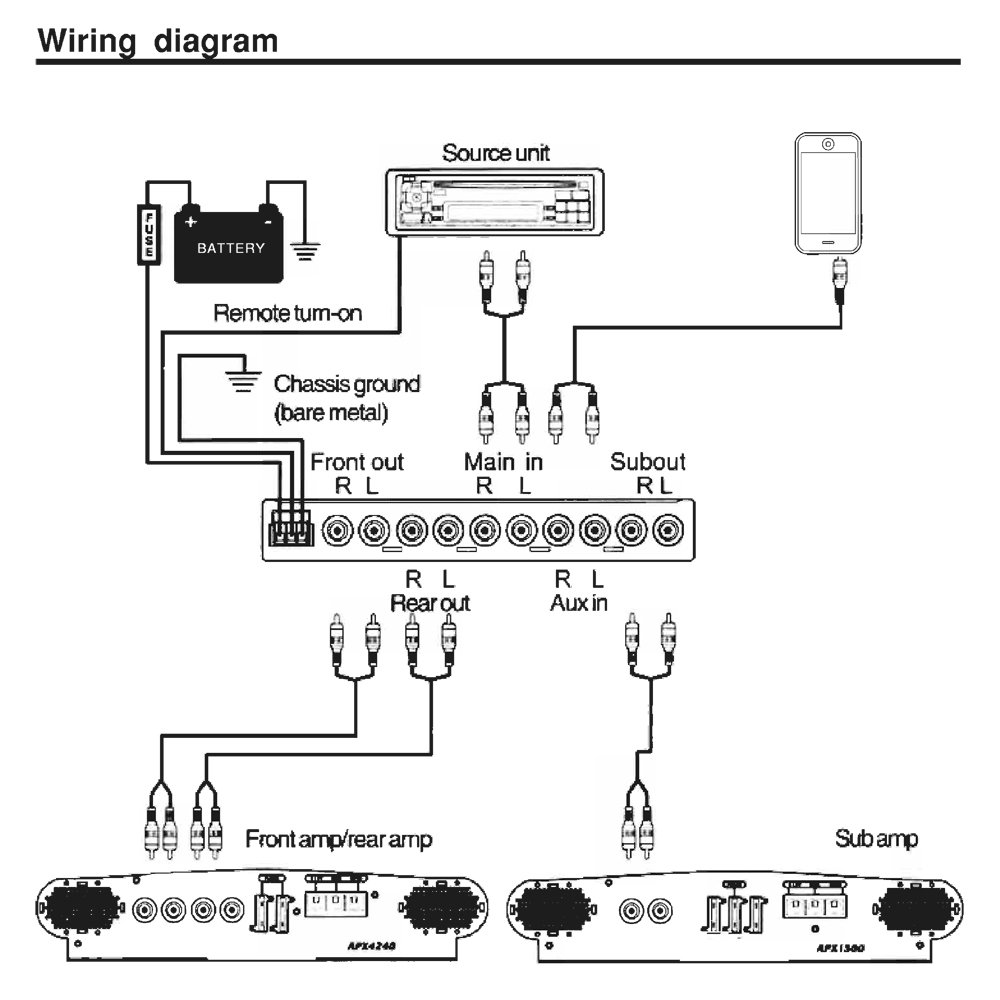
Oct 07, 2021 · This wiring diagram shows how a full-blown car audio system upgrade gets wired in a car. The system depicted includes new speakers, an aftermarket receiver, a 4-channel amp for the front and rear pairs of full-range speakers, and a mono amp for a subwoofer. The extra gear you'll need for wiring the amps includes: a dual amplifier wiring kit

How to make a simple audio pre-amplifier
Wiring and Controls Diagram. Marine Amplifier & Speaker System. 4-Channel Marine Power Amplifier/Public Address System. • Maximum Power have provided the connections at the end of waterproof wires/cables, and . well I bought the 2 channel amp and some mtx thunder marine speakers. I got the power thing down as well as the speaker wires too.
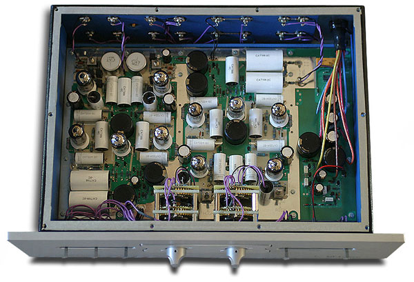
CAT SL1 Legend Preamplifier - ACA
guitar amp speaker wiring diagram wiring diagram database amplifier wiring diagrams how to add an amplifier to your car audio. A set of wiring diagrams may be required by the electrical inspection authority to accept connection of the house to the public electrical supply system.

Car Amplifier Wiring Diagram Installation - Decoration Ideas
Mar 04, 2021 · You may also wonder if you can connect a preamp into an integrated amplifier. You can definitely do this, but there are some major things to consider. Steps for Connecting a Preamp to a Receiver. Connecting a preamp to your AV receiver isn’t hard if your receiver has a HT Bypass or Direct In input.

Pin on Cool ideas
The Sonos CONNECT:AMP includes a built-in state-of-the-art digital amplifier that . wiring, you can make a wired connection to the additional Sonos products.2 - Get a 2nd CONNECT:AMP to drive your patio speakers 3 - Return the CONNECT:AMP and get a CONNECT along with a separate amp that is built to drive all 3 of your speaker pairs.
eBay FAQ
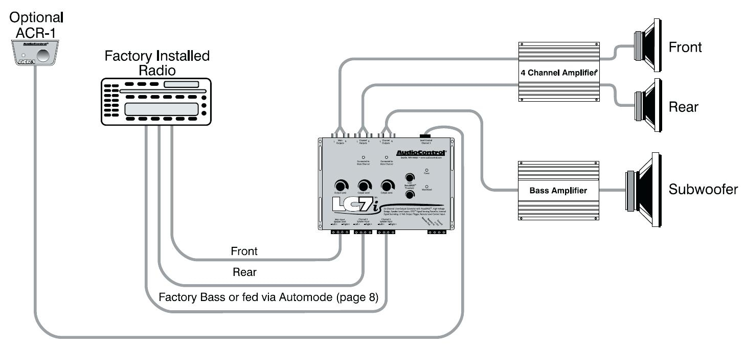
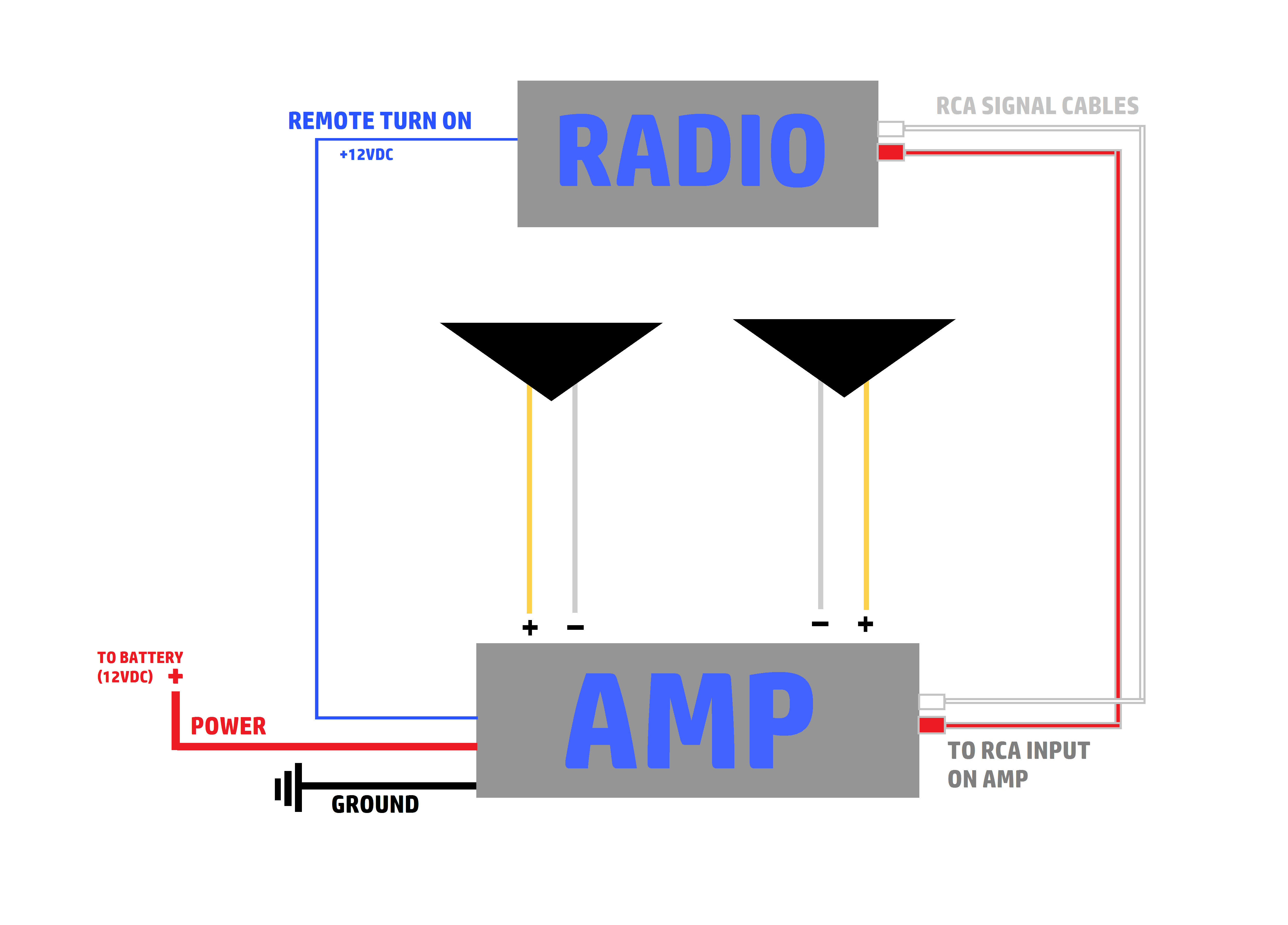
How-to-guides: Amplifier wiring diagrams for power and speakers. Amplifier wiring diagrams for connecting audio RCA and speaker level inputs. Side view of amplifier audio input terminal view, may vary from model to model. Whether your wiring your amplifier with preamp out input or using the radio amplified speaker output to drive your amplifier.

unknown
2. Connect the negative terminal of the left side speaker to the negative terminal of the left speaker out terminal of the amplifier. 3. Connect the positive terminal of the right-side speaker to the positive terminal of the right speaker out terminal of the amplifier. 4.
Mono Amp 2 Speaker Wiring Diagram - Wiring Diagram
The internal connection diagram of JRC4558 is shown below. 4558 Ic Preamplifier Circuit Diagram. Jrc 4558 preamp circuit diagram riaa preamplifier using njm4558 audio pre amplifier mic ic microphone red page173 bass mid treble tone control circuits 2 1 filter portable phono page160 nerv ic4558 cirquit design archives circuits99.
white usb cable plugged in white electric socket
Stereo wiring diagrams illustrate how to connect a receiver or amplifier to other components in a stereo system. A stereo wiring diagram is a helpful guide for installing their stereo system and should include component placement and color codes for speaker wires.

4558 ic Circuit Diagram | Audio Power Amplifier ...
Audio Systems. الذخيرة روسيا هدف connect 4 speakers to 2 1 channel mosfet powerd amplifier digital amp front and rear 4ohm a audio systems the speaker wiring diagram subwoofer diagrams how wire 6 car amplifiers add bridge an mono sub plus s2ki matching info guide blaupunkt power installation 5 simple step switch between two on ...

siwire: Tda7294 Subwoofer Schematic
If your future preamp has balanced outputs, you can use a balanced cable to the amp's input with either a 1/4 to 1/4 TRS (tip-ring-sleeve (aka "stereo" 1/4 in cable) cable, a short "mic" cable or one with 1/4 on one end, XLR on the other. If not, a short 1/4 to 1/4 in TS (tip-sleeve (aka "Mono" 1/4 in. cable) is just fine.

Passive Speaker Crossover Wiring Diagram - Wire
A preamplifier (preamp) is an electronic amplifier that prepares a small ... 12V Amplifier Circuit with TDA2003 4558 preamplifier schematic Dc Circuit, ...

Sub Car Amplifier Wiring Diagram Installation For Your Needs
In this post, you’ll find clear and detailed speaker wiring diagrams to help (and that you can print out if you like, too!). I’ll go into detail about the right and wrong way to wire speakers and connect them properly to your stereo or amplifier. It’s actually pretty simple once you learn the basics.

How to make 2000W amplifiers Circuit diagram at home | www ...
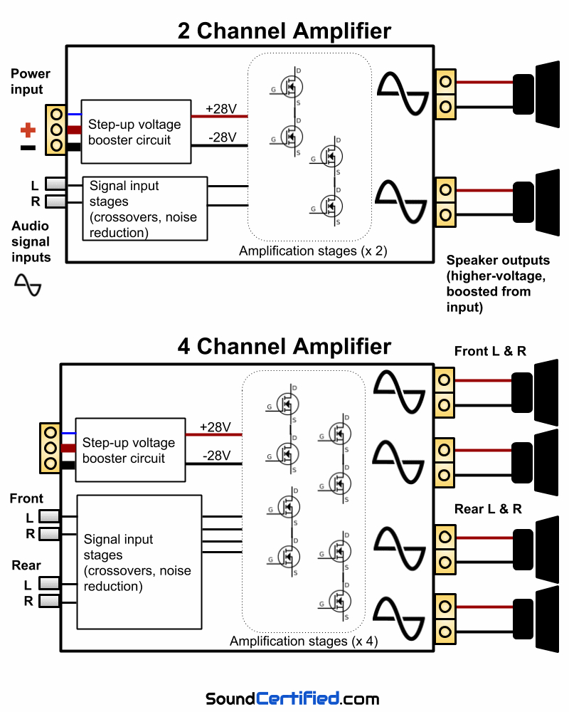
4 Channel Amplifier Wiring Diagram - wiring diagram is a simplified normal pictorial representation of an electrical circuit. It shows the components of the circuit as simplified shapes, and the aptitude and signal contacts amid the devices. A wiring diagram usually gives counsel not quite the relative perspective and treaty of devices and ...

iPad Audio Desk Schematic
Amplifier Ne5532 Preamp Preamplifier Volume Tone Control Finished Board Dual Ac 12v 18v Audio Power. A ne5532 audio preamplifier circuit bass mid treble tone control circuits pre mic microphone how does amplifier project 158 pinout datasheet features diagram universal preamplifiers using high quality preamp three of controls simple headphone op amp ic 18v power board for shure low noise fever ...
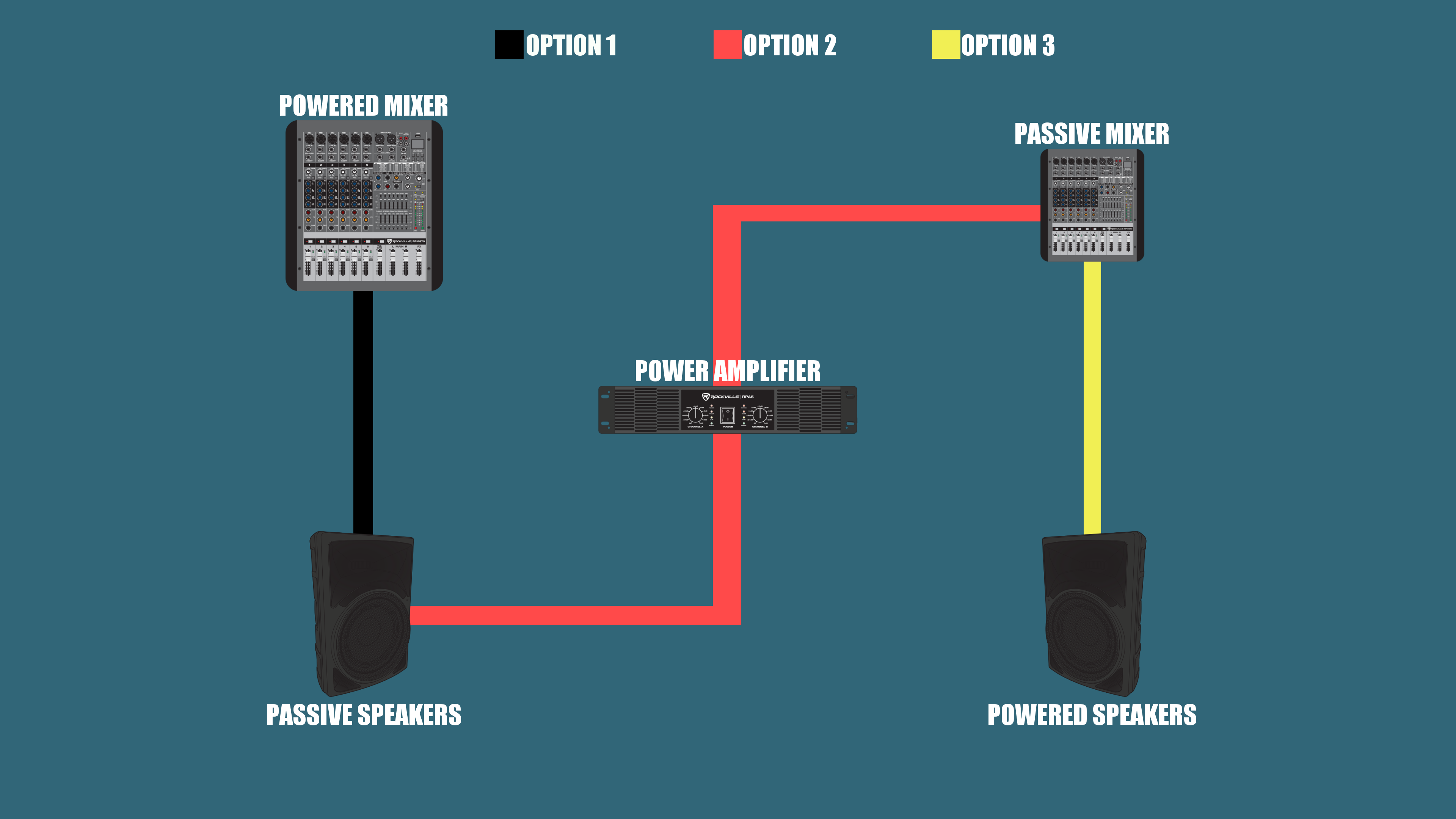
What is a Mixer? How do I use one? - Rockville University ...
Buck i have a alpine mrv f340 amp and 2 alpine type r 12 swr 1241d subs. Amp to head unit wiring diagram. I have built the boxes to spec for these subs 2 boxes rather than 1. The rest of your system should resemble this amplifier wiring diagram with your second battery essentially taking the place of the diagram s capacitor.
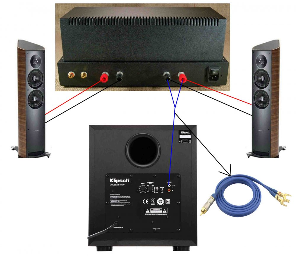
Stereo to subwoofer amp connection - Subwoofers - The ...
Sep 3, 2021 — The circuit diagram can be seen below. The circuit is self explanatory, and can be integrated with any standard power amp for further ...
How To Connect Equalizer To Amplifier Diagram - Wiring Diagram
To connect an integrated amplifier to an AV receiver using RCA Cables, find the pre-out section on the AV receiver and connect to the Left and Right channels. Then, connect these to the Integrated Amplifier, and finally, plug in your speaker wire to the Integrated Amp to achieve sound. While there are several different routes that you could ...

selective focus photography of machine with gears
Subwoofer Wiring Diagrams. Step #1 - Choose the # of subwoofers you will wire in your system from one amplifier output. Step #2 - Specify 2 or 4 ohm single voice coil OR 2 or 4 ohm dual voice coil subwoofer (s) The Subwoofer Wiring Diagram tool will then display two wiring options with the final impedance at the amplifier.

15 Stunning Crossover Wiring Diagram Car Audio Design ...

Amp Wiring Kit Diagram | schematic and wiring diagram

Schema Tda 2040 Stereo Awesome | Wiring Diagram Image

2 Amps 2 Subs Wiring Diagram
Amazon.com: Pyle PLE780P Single/Double-DIN 7-Band ...
Free Wiring Diagram: Amplifier Power Watts Transistor ...
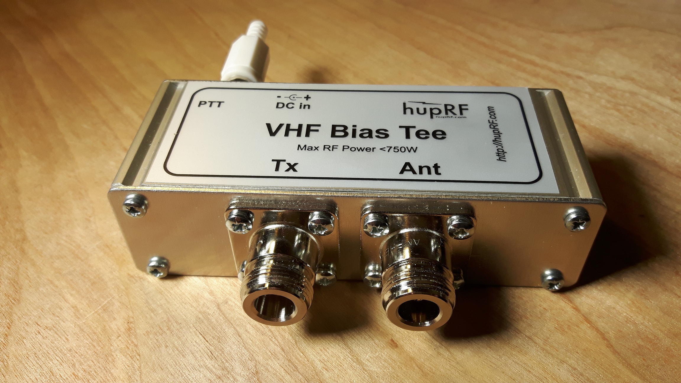
Bias Tee (DC Injector) for VHF DCI-VS | hupRF

How do AV receivers work? - Best AV Receiver

Can a subwoofer amplifier (-)output be grounded ? | All ...
Car Amplifier Wiring Diagram Installation | Wiring Diagram

2.5 watts lm 380n amplifier with stable wiring diagram.
assorted guitar pedal lot beside electric guitar and amplifie
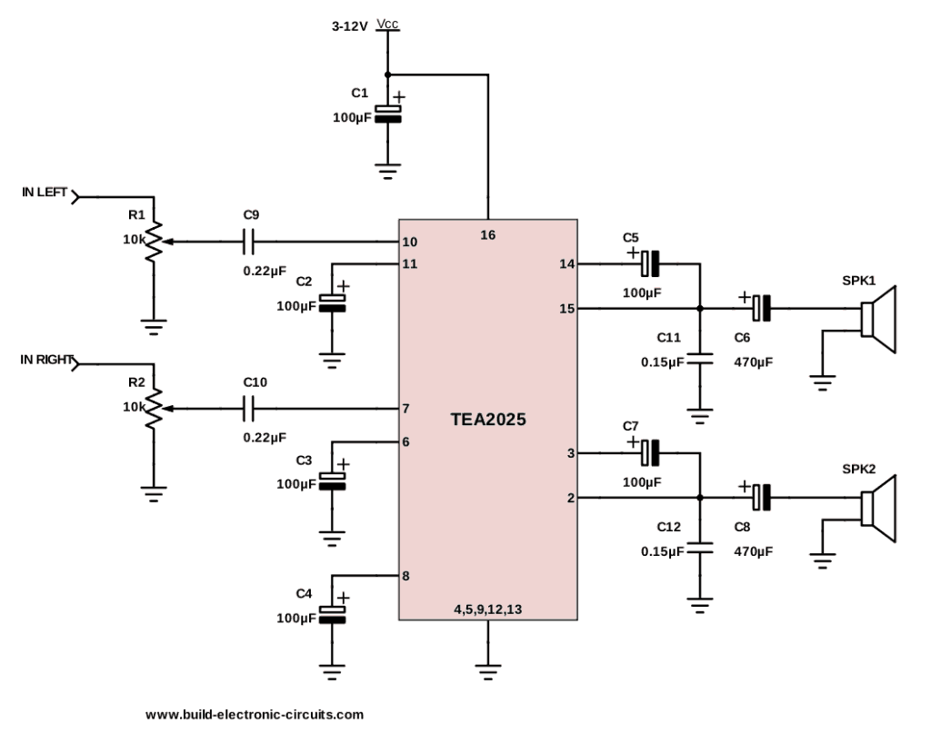
The Simplest Audio Amplifier Circuit Diagram
Amp Wiring Diagram - Cadician's Blog

BM-3000 Connection Diagram - Best Media Tech Support

man and woman holding hands on street
0 Response to "37 preamp to amp connection diagram"
Post a Comment