42 ray diagram for converging lens
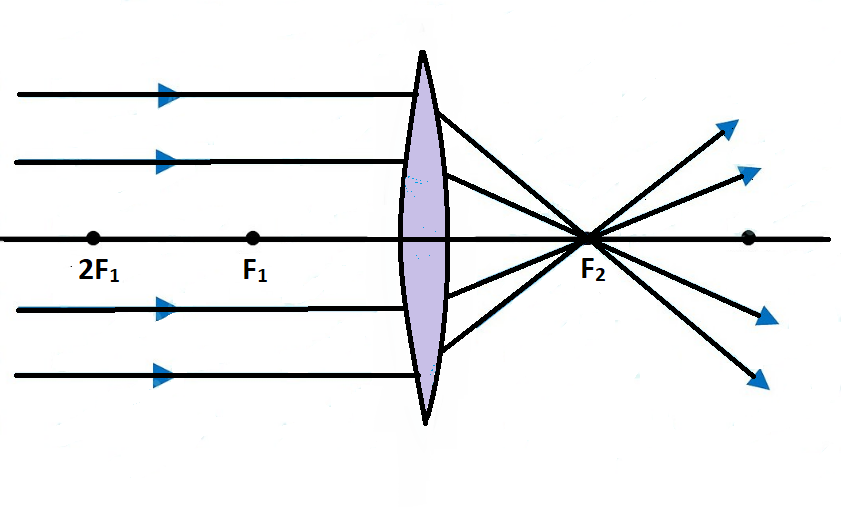
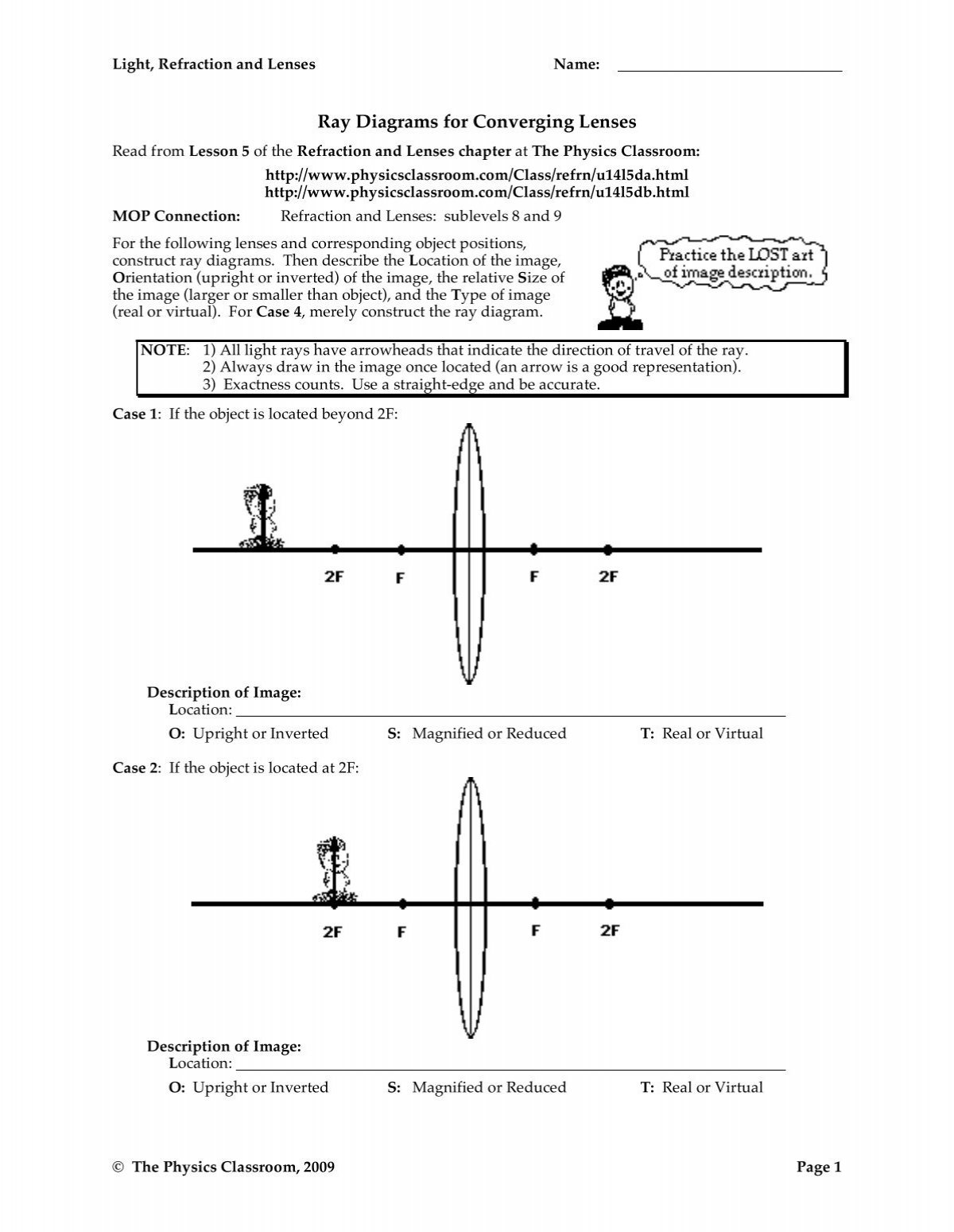
(The axis is defined to be a line normal to the lens at its center, as shown in Figure 1.) Such a lens is called a converging (or convex) lens for the converging effect it has on light rays. An expanded view of the path of one ray through the lens is shown, to illustrate how the ray changes direction both as it enters and as it leaves the lens. The Physics Classroom » Curriculum Corner » Refraction and Lenses » Ray Diagrams for Converging Lenses. The document shown below can be downloaded and printed. Teachers are granted permission to use them freely with their students and to use it as part of their curriculum. Visit the Usage Policy page for additional information.
Step-by-Step Method for Drawing Ray Diagrams. Pick a point on the top of the object and draw three incident rays traveling towards the lens. Once these incident rays strike the lens, refract them according to the three rules of refraction for converging lenses. Mark the image of the top of the object. Click to read full answer.

Ray diagram for converging lens
Ray Diagrams for Lenses. Three principal rays can be used to locate and size the image formed by a single lens, with examples for converging and diverging lenses. The three principal rays are:. A ray from the top of the object proceeding parallel to the centerline perpendicular to the lens, passing through the principal focal point beyond the lens. This Demonstration lets you visualize the ray diagrams for converging and diverging lenses. By manipulating the object and lens locations, you can create real or virtual images. The rays parallel to the principal axis and the ray through the center of the lens are drawn.Locators allow you to drag both the object and the lens. You can change the focal length using a slider. An incident ray traveling through the exact center of the lens will refract upon entering the lens and upon leaving the lens and continue traveling in its original direction. How can a ray diagram be used to locate the approximate location, relative size, and orientation of an image for a converging lens?
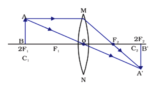
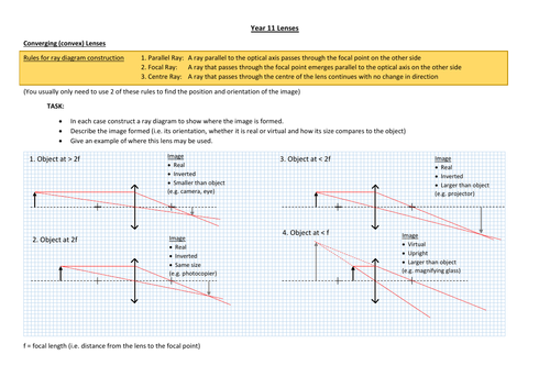
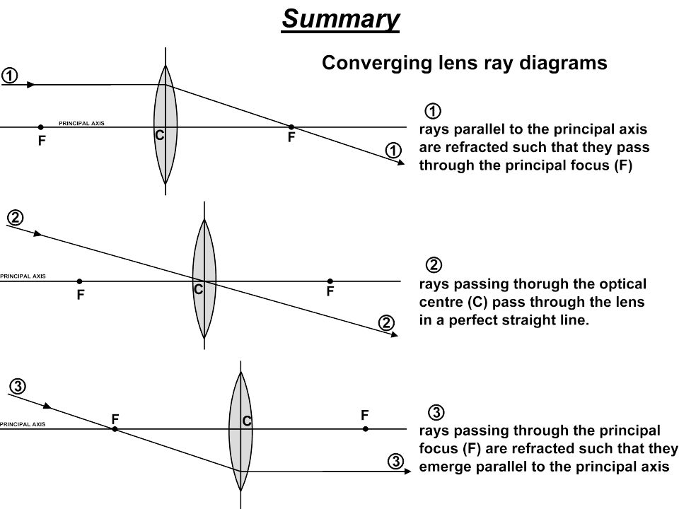
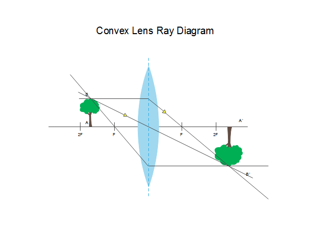
Ray diagram for converging lens. Trick to drawing ray diagrams for converging lens: There is one ray of light passing through the center of the lens. Always. 2 rays are enough to determine the position of image/object. The other ray of light ALWAYS passes through the focal point of the lens. Either the first focal point of the second focal point. If a ray passes through the focal point before passing through the lens, the ... Here you have the ray diagrams used to find the image position for a converging lens. You can also illustrate the magnification of a lens and the difference between real and virtual images. Ray diagrams are constructed by taking the path of two distinct rays from a single point on the object. A light ray that enters the lens is an incident ray. This interactive tutorial utilizes ray traces to explore how images are formed by the three primary types of converging lenses, and the relationship between the object and the image formed by the lens as a function of distance between the object and the focal points. Ray diagrams for converging lens cases. Here is a video from Khan Academy that shows the ray geometry that explains the image formation for four different object distances relative to the lens and its focal points. A few key concepts are: YouTube. Light is reflecting from the o bject in all directions, but the only rays shown are the ones that ...
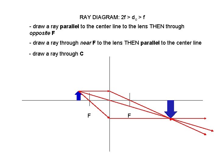
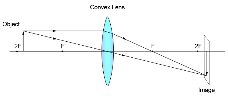
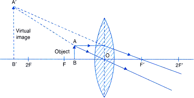
Ray diagram for converging lens. Ray 1 is parallel to the axis and refracts as if from F. Ray 2 heads towards F' before refracting parallel to the axis. Ray 3 passes straight through the center of the lens. image is always virtual, upright and reduced O F I F' Ray diagram for diverging lens Description of how to draw ray diagrams for converging lenses for grade 10 science. Ray diagrams for the thin lens. We have already discussed the use of a thin convex lens ( a converging lens) as a magnifying glass. If a small object is placed on the optical axis at a greater distance from the optical centre C than the focal length then the rays from each point on the object will be focused to a point on the opposite side of ... Ray diagram for an object placed between 2F and F from a convex lens In a film or data projector, this image is formed on a screen. Film must be loaded into the projector upside down so the ...
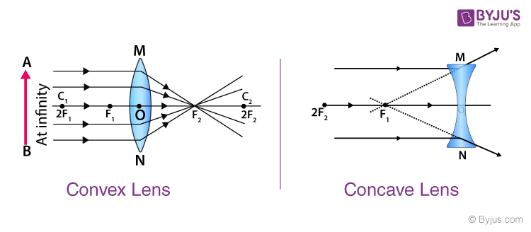
A converging lens is an optical lens that converges all rays of light passing through it. The primary purpose of a converging lens is to focus the incoming rays from an object and converge them to form an image. The image can be magnified, diminished, or remain the same depending on the distance of the object from the lens. Ray diagram for converging lenses. Converging and diverging lenses ray diagrams. There is one ray of light passing through the center of the lens. A virtual image is formed if the object is located less than one focal length from the converging lens. 10 draw a ray diagram for a 30 cm tall object placed 100 cm from a converging lens having a ... The lens in a film, slide or video projector is a converging lens. In this diagram the lens produces a real image, which can be projected on a screen. You can see that the image is upside down (inverted) and magnified. To avoid having to stand on your head to see the picture the object to be projected is inserted into the projector upside down, so the image comes out the right way up. Ray Diagrams for Lenses. The image formed by a single lens can be located and sized with three principal rays. Examples are given for converging and diverging lenses and for the cases where the object is inside and outside the principal focal length. The "three principal rays" which are used for visualizing the image location and size are:
Action Of A Thin Converging Lens Definition Examples Diagrams
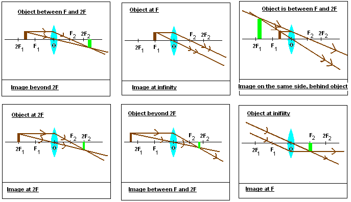
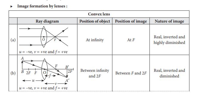
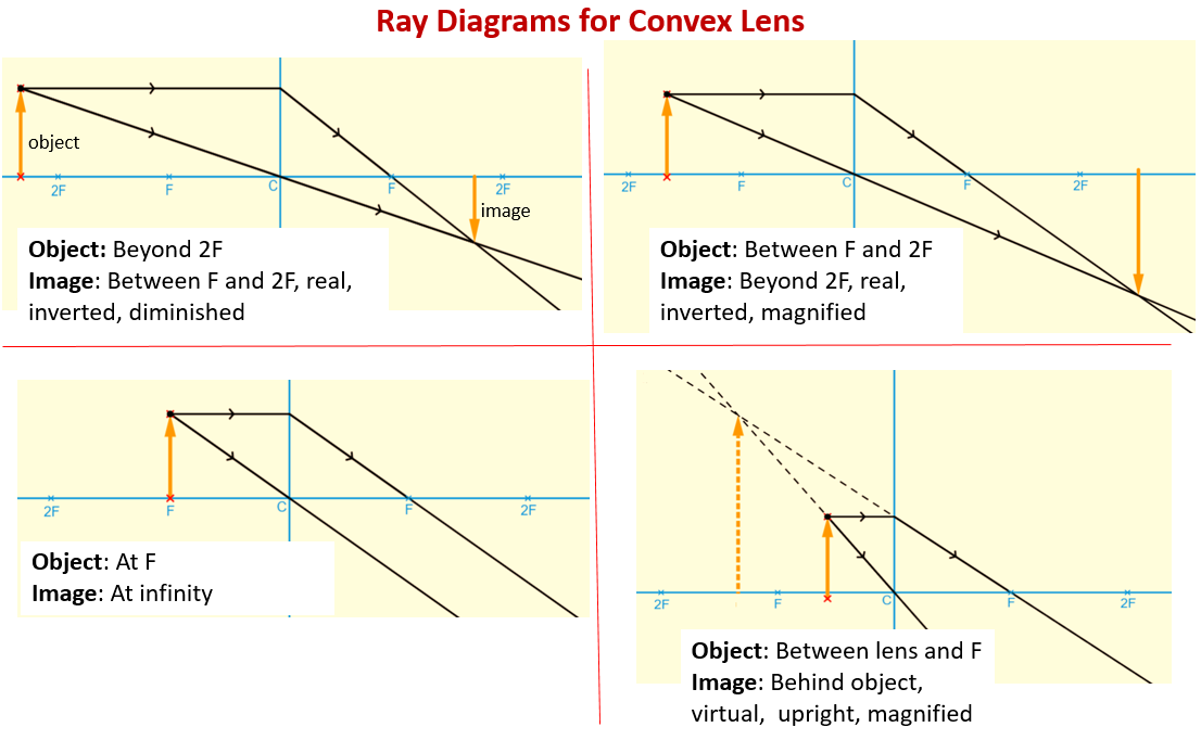
Ray Diagram for Object Located in Front of the Focal Point. In the three cases described above - the case of the object being located beyond 2F, the case of the object being located at 2F, and the case of the object being located between 2F and F - light rays are converging to a point after refracting through the lens. In such cases, a real image is formed.

A Draw A Ray Diagram For The Following Si Clutch Prep
For a Concave lens,There are only 2 casesThey areObject is Placed at InfinityObject is Placed between Infinity and Optical CenterCase 1 - Object is Placed at infinityIn this Case, Object is kept far away from mirror (almost at infinite distance)So, we draw rays parallel to principal axisSince ray pa

Ray Diagram For A Convex Lens Physics And Mathematics Physics Geometrical Optics
Ray Diagrams By constructing a ray diagram, we can determine where the image is located, and what it will look like. A ray diagram is a diagram showing rays that can be drawn to determine the size and location of an image formed by a mirror or lens.
Answered Sketch A Ray Diagram For A Concave Bartleby
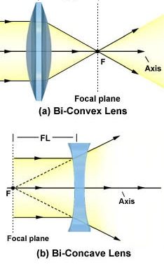
A convex lens is thicker in the middle than it is at the edges. Parallel light rays that enter the lens converge. They come together at a point called the principal focus. In a ray diagram, a ...
Gcse Physics Ray Diagram For An Image Made By A Convex Lens What Is A Real Image What Is An Inverted Image Gcse Science
A ray diagram using this virtual object shows the location of the final image (bottom part of Figure O). Numerically, we can verify the accuracy of the ray diagram with: An arrow is placed 50 cm away from a converging lens (f= 25cm). On the other side of this first lens is a second converging lens (f. Ray Diagrams for Lenses. The image formed ...

Solved Choose The Correct Ray Diagram For A Convex Lens Chegg Com
Draw a ray diagram to show how a converging lens is used as a magnifying glass to observe a small object. Mark on your diagram the foci of the lens and the position of the eye. Medium. Open in App. Solution. Verified by Toppr. The object is placed between the focal point F 1 ...
1
Shows how to draw ray diagrams to locate the image formed by a convex lens. You can see a listing of all my videos at my website, http://www.stepbystepscienc...
Draw Ray Diagram Showing The Image Formation By A Convex Class 12 Physics Cbse
Real images occur when objects are placed outside the focal length of a converging lens (s>f). If the lens is converging but the distance from the object to the lens is smaller than the focal length, the image will be virtual. Diverging lenses always produce virtual images. This calculator shows a ray diagram when the image is real. Magnification
Lenses And Images Physclips Light
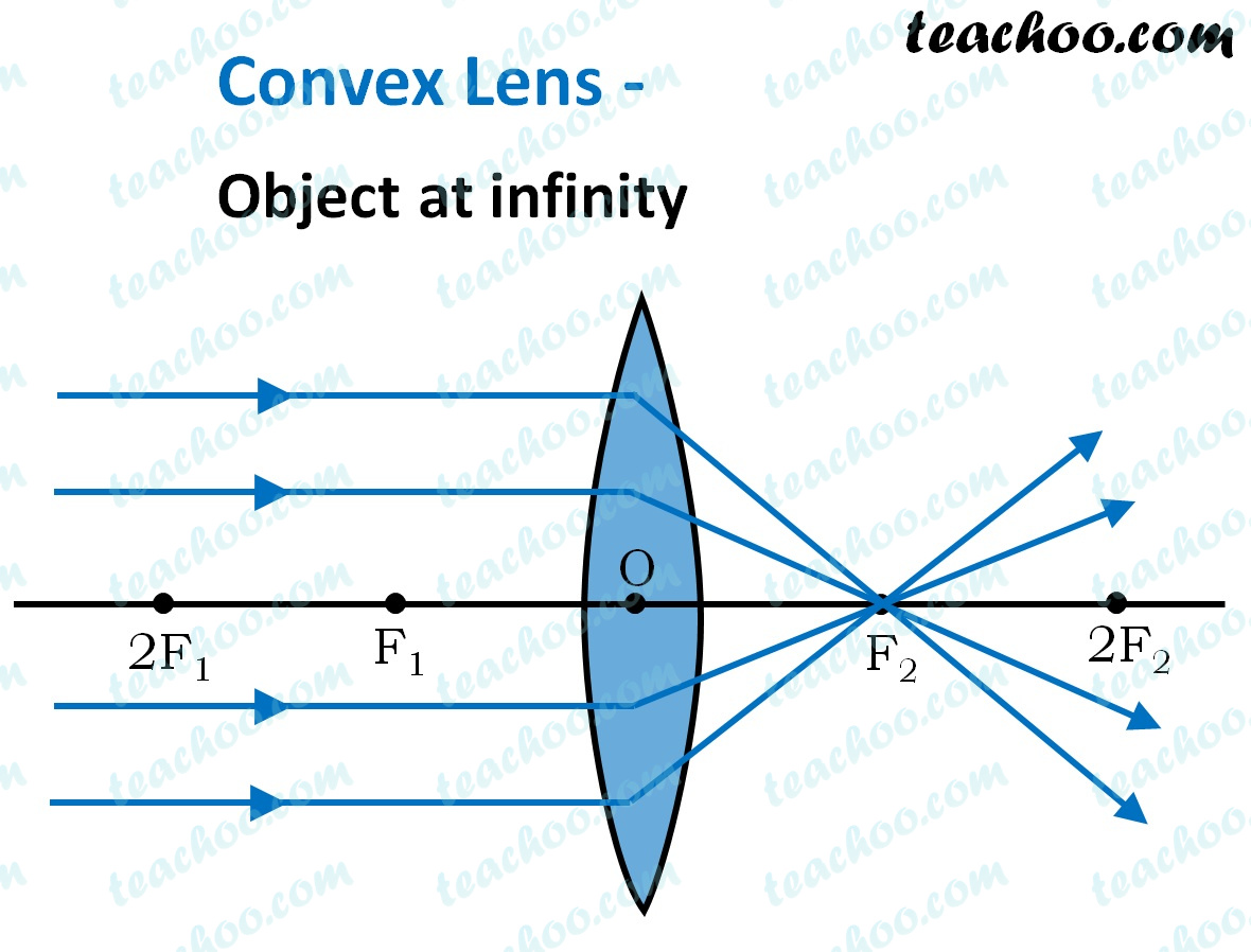
Convex Lens - Ray diagram. Last updated at April 26, 2020 by Teachoo. For a Convex Lens, object can be kept at different positions Hence, we take different cases Case 1 - Object is Placed at infinity In this Case, Object is kept far away from lens (almost at infinite distance)

Converging Diverging Lenses Ray Diagrams Directions Use At Least Two 2 Rays With Different Colors Homeworklib
Convex Lens Ray Diagrams For lenses, the following three rays are typically used in ray diagrams. Keep in mind that an inflnite number of rays actually form the image. Ray # 1 For a lens, the flrst ray starts from the top of the object and extends parallel to the optical axis to the center of the lens. This ray, for a converging (convex) lens,
Lenses Ray Diagram Construction Worksheet Teaching Resources
A convex lens ray diagram is a simple way of visualising the path that light rays take when passing through a convex lens. To draw a ray diagram and find ...
Ray Diagrams For Lenses Convex Converging Lens All
Ray diagram for object located at the focal point thus far we have seen via ray diagrams that a real image is produced when an object is located more than one focal length from a converging lens. The ray passing through the focal point becomes parallel to the principal axis after refraction by the lens.

Ejss Model Newtonscadlerealwee
Diverging Lenses As such, the rules for how light behaves when going through a diverging lens is a little bit different. You will be expected to be able to draw a Ray Diagram of a converging and diverging lens on our upcoming test without the rules.
Waves Drawing Ray Diagrams For Converging Lenses Ppt Download
(converging) lens. Complete the ray diagram to show how the lens produces an image of the object. F = Principal focus (4) (b) State two words to describe the nature of the image produced by the lens in the camera. 1. _____ 2. _____ (2) (Total 6 marks) Q2. (a) The diagram shows how parallel rays of light pass through a convex lens.
Lenses And Images Physclips Light
5) virtual, inverted, and diminished. Page 7. A real image is formed by a converging lens. If a weak ...15 pages
Ray Diagrams For Lenses
Ray Diagrams: Converging Lenses ... A converging lens (also known as a convex lens) brings light to a focus, resulting in the formation of a real ...

Blog In Physics Ray Diagram For Converging Lens
An incident ray traveling through the exact center of the lens will refract upon entering the lens and upon leaving the lens and continue traveling in its original direction. How can a ray diagram be used to locate the approximate location, relative size, and orientation of an image for a converging lens?
Convex Lens Ray Diagram Free Convex Lens Ray Diagram Templates
This Demonstration lets you visualize the ray diagrams for converging and diverging lenses. By manipulating the object and lens locations, you can create real or virtual images. The rays parallel to the principal axis and the ray through the center of the lens are drawn.Locators allow you to drag both the object and the lens. You can change the focal length using a slider.
Concave And Convex Lenses Image Formation Curvature Focus
Ray Diagrams for Lenses. Three principal rays can be used to locate and size the image formed by a single lens, with examples for converging and diverging lenses. The three principal rays are:. A ray from the top of the object proceeding parallel to the centerline perpendicular to the lens, passing through the principal focal point beyond the lens.

Ray Diagrams For Image Formation Of A Converging Bi Convex Lens And Download Scientific Diagram

Igcse Physics Unit 3 Properties Of Waves
Nanopdf Com

Converging And Diverging Lenses Pdf Converging Diverging Lenses Ray Diagrams 1 1drawa 1drew Aragthrough Focalpointandbent Topanda With Pi The Parreld Course Hero
Multimedia Learning Objects Repository
1
Sfu Ca
Convex Lens Object Between 2f And F
Terminologies Related To Lens And Rules For Drawing Ray Diagrams Online Science Notes

Physics Optics Lenses 2 Of 5 Lens Combinations Two Converging Lenses Youtube
Ray Diagrams For Convex Lens Online Science Home Work
Explain With The Help Of A Diagram Why The Convex Lens Is Also Called A Converging Lens Studyrankersonline
Convex Lens Ray Diagram Image Formation Table Teachoo
Ray Diagrams For Images Formed By Convex Concave Lenses Quick Reference
Convex Lenses And Ray Diagrams Examples Solutions Videos Notes
Draw Ray Diagrams To Show The Formation Of A Three Times Magnified I Real Image Ii Virtual Image Of An Object Kept In Front Of A Converging Lens Mark The Positions Of Object
Ray Diagrams For Converging Lenses The Physics Classroom

At 2f1 Explain With The Help Of Ray Diagram Of Convex Lens To Show The Position Of Image
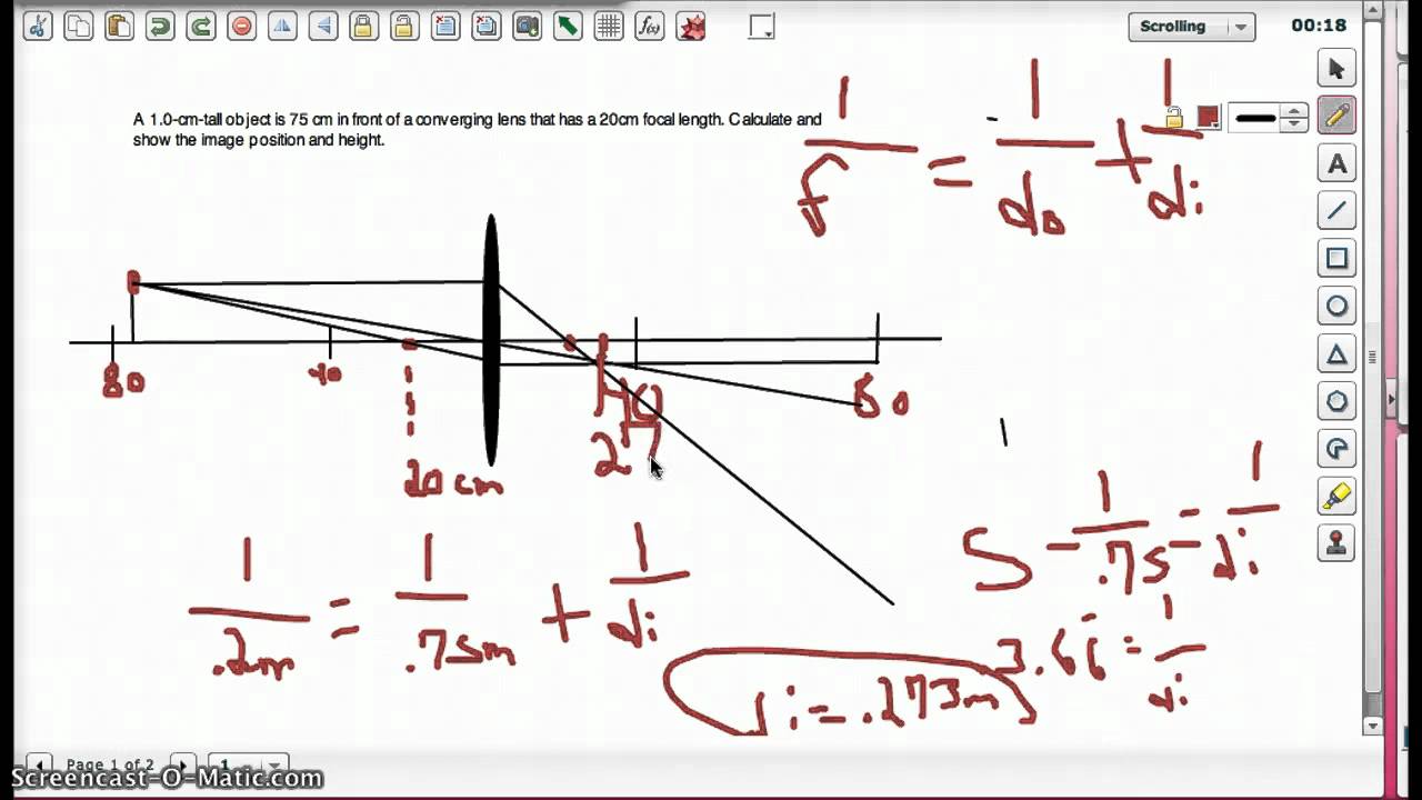
Lens Equation And Ray Diagram Converging Lens Example Youtube
---teachoo.png)
Convex Lens Ray Diagram Image Formation Table Teachoo

Ray Diagrams For Converging Lens Cases Sat Ii Physics Notes

Omtex Classes Draw A Ray Diagram For Object Position Beyond 2f1 For A Convex Lens

Drawing Ray Diagrams For A Converging Lens The Fizzics Organization
0 Response to "42 ray diagram for converging lens"
Post a Comment