41 moody diagram friction factor
How to use a Moody Chart (Moody Diagram) to determine friction factors in steady state pipe flow.11 Aug 2017 Another possibility is to use the Moody Diagram which is actually a friction factor chart where the friction factor can be read directly. 3. Hagen-Poiseuille relation In Laminar regime, the volumic flowrate can be calculated thanks to the Hagen-Poiseuille equation. Q=volumic flowrate in m3/s ...
The work of Moody, and the Moody Diagram on page 6 72 of the published transactions, has become the basis for many of the calculations on friction loss in pipes, ductwork and flues. While there are modified versions of the original Moody Diagram, I will strive to use the original diagram as the basis for terminology used here.
Moody diagram friction factor
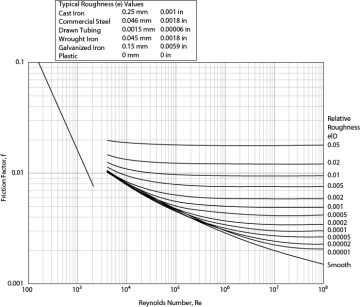
The Moody diagram (also known as the Moody chart) is a graph in a non-dimensional form that relates the Darcy friction factor, Reynolds number, ... History. In 1944, Lewis Ferry Moody plotted the Darcy–Weisbach friction factor against Reynolds number Re for various values of relative roughness ε / D. This chart became commonly known as the Moody Chart or Moody Diagram. It adapts the work of Hunter Rouse but uses the more practical choice of coordinates employed by R. J. S. Pigott, whose work was based upon an analysis of some 10,000 ... The most common method to determine a friction factor for turbulent flow is to use the Moody chart. The Moody chart (also known as the Moody diagram) is a log-log plot of the Colebrook correlation that relates the Darcy friction factor, Reynolds number, and the relative roughness for fully developed flow in a circular pipe.
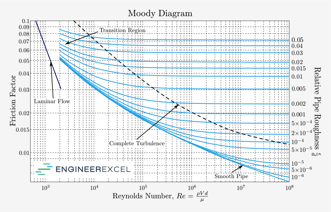
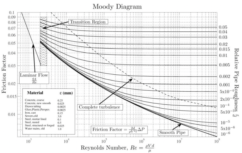
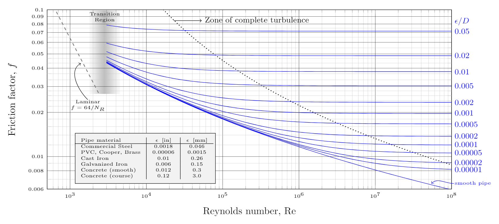
Moody diagram friction factor. Figure 11-4 is a Moody friction factor chart covering the full range of flow conditions. It is a log-log graph of (log f ) versus (log n r e ) Due to the characteristics of the complex nature of the curves, the equation for the friction factor in terms of the Reynolds number and relative roughness varies for each of the four regions. Friction Chart or Moody Chart. The value of f, Darcy friction factor is taken from Moody Diagram. The friction factor for laminar flow is calculated by dividing 64 by the Reynold’s number. Friction factor (for laminar flow) = 64 / Re ; This is for circular pipes. For Non-Circular Pipes; f=k/Re ; where k lies between 48 to 96. SI based Moody Diagram. The Moody friction factor - λ (or f) - is used in the Darcy-Weisbach major loss equation. The coefficient can be estimated with the diagram below: If the flow is transient - 2300 < Re < 4000 - the flow varies between laminar and turbulent flow and the friction coefiicient is not possible to determine. Friction factor for turbulent pipe flows — The Moody diagram is a chart showing the Darcy friction factor of a pipe as a function of the Reynolds number for ...
The Moody diagram. The friction factor is used to calculate the pressure drop due to the flow of a fluid in a pipe. It represents the interaction in between the fluid and the pipe. There are different ways to calculate it, one can be graphical, using a Moody graph. Note that the friction factor used here is Darcy (also called Darcy-Wesibach or ... The friction factor or Moody chart is the plot of the relative roughness (e/D) of a pipe against the Reynold's number. The blue lines plot the friction factor for flow in the wholly turbulent region of the chart, while the straight black line plots the friction factor for flow in the wholly laminar region of the chart. In 1944, LF Moody plotted ... Weisbach equation, it is more convenient to use equations for the Moody friction factor, f, rather than a graph like the Moody diagram. There are indeed equations available that give the relationships between Moody friction factor and Re & /D for four different portions of the Moody diagram. The four portions of the Moody diagram are: The most common method to determine a friction factor for turbulent flow is to use the Moody chart. The Moody chart (also known as the Moody diagram) is a log-log plot of the Colebrook correlation that relates the Darcy friction factor, Reynolds number, and the relative roughness for fully developed flow in a circular pipe.
History. In 1944, Lewis Ferry Moody plotted the Darcy–Weisbach friction factor against Reynolds number Re for various values of relative roughness ε / D. This chart became commonly known as the Moody Chart or Moody Diagram. It adapts the work of Hunter Rouse but uses the more practical choice of coordinates employed by R. J. S. Pigott, whose work was based upon an analysis of some 10,000 ... The Moody diagram (also known as the Moody chart) is a graph in a non-dimensional form that relates the Darcy friction factor, Reynolds number, ...

Heat Transfer By Convection Basic Concept Of Convection Methodology To Solve Problems Physical And Thermal Properties Of Liquids Physical And Thermal Properties Of Air And Water Heat Transfer Coefficient For Transition Flow Inside A Pipe Duniakumu

Major And Minor Head Losses In A Hydraulic Flow Circuit Experimental Measurements And A Moody S Diagram Application

Characterization Of Surface Roughness Effects On Pressure Drop In Single Phase Flow In Minichannels Physics Of Fluids Vol 17 No 10

Moody Friction Factor Calculator From Innovyze H2ocalc Swmm5 And Swmm5 Features In Autodesk Innovyze Infoswmm Icm Swmm Icm And Xpswmm

Figure 7 From Leakage Tests Of Wet Co2 Gas With Oil Mixture In Scroll Compressors And Its Use In Simulations Of Optimal Performance Semantic Scholar










0 Response to "41 moody diagram friction factor"
Post a Comment