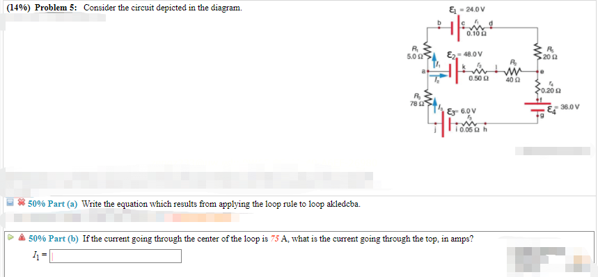
41 consider the circuit depicted in the diagram
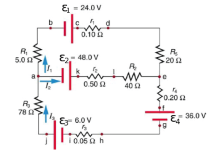
Consider the circuit diagram depicted in the figure. Consider the circuit diagram depicted in the figure. It is known that two 25ω 24v and ε2 36v. What equation do you get when you apply the loop rule to the loop abcdefgha in terms of the variables in the figure. F in d the values of the voltage vc and the current ib. Transcribed image text: (6%) Problem 12: Consider the circuit depicted in the diagram. & 24.0 V 0.10 S2 E2 48.0 V 5.02 20 S2 0.50 2 400 0.20 2 78 Ei 36.0 V ...
EXAMPLE PROBLEMS AND SOLUTIONS A-3-1. Simplify the block diagram shown in Figure 3-42. Solution. First, move the branch point of the path involving HI outside the loop involving H,, as shown in Figure 3-43(a).Then eliminating two loops results in Figure 3-43(b).Combining two

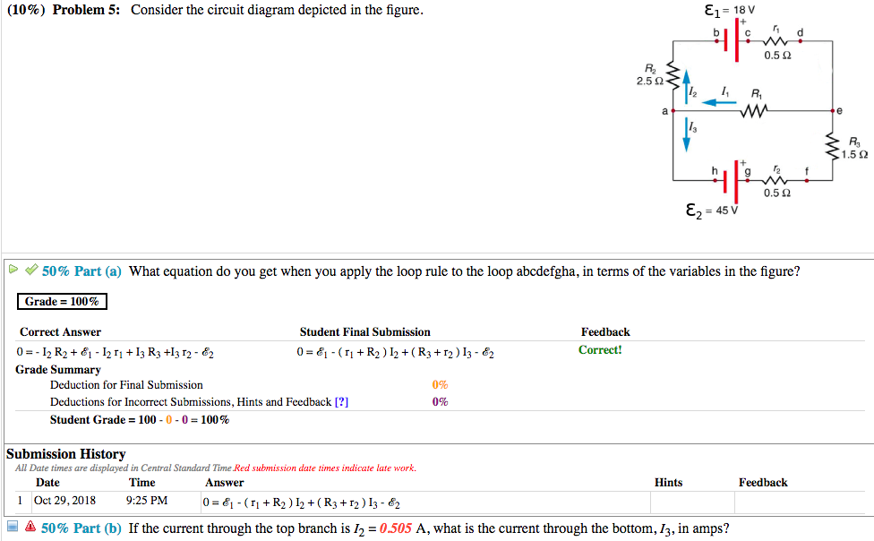
Consider the circuit depicted in the diagram
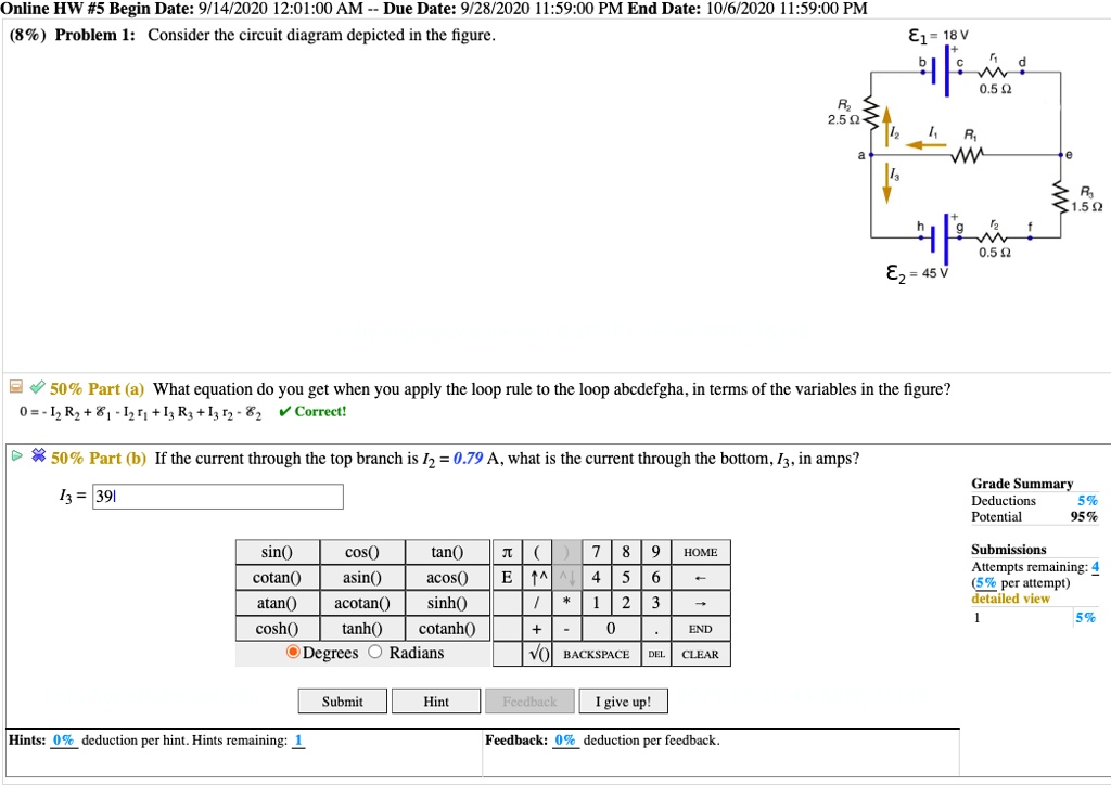
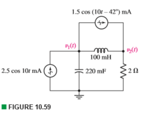
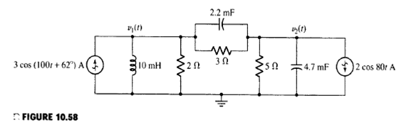
depicted. Rule 2. In circuits which have combinations of L, C & R in SERIES (studied in Module 8) it is customary to draw the phasor representing CURRENT horizontally, and call this the REFERENCE phasor. This is because the current in a series circuit is common to all the components. Rule 3. In parallel circuits, (studied in Module 9) the Consider the circuit below. Since the 4-ohm resistor is in parallel with the capacitor, i(0+) = v C(0+)/4 = 0/4 = 0 A Also, since the 6-ohm resistor is in series with the inductor, v(0+) = 6i L(0+) = 0V. (b) di(0+)/dt = d(v R(0+)/R)/dt = (1/R)dv R(0+)/dt = (1/R)dv C(0+)/dt = (1/4)4/0.25 A/s = 4 A/s v = 6i L or ... Transcribed image text: (10%) Problem 5: Consider the circuit diagram depicted in the figure 0.5 Ω R2 2.5 Ω /2 R 1.5Ω 0.5 Ω 50% Part (a) what equation do you get when you apply the loop rule to the loop abcdergha, in terms of the variables in the figure? Grade= 100% Correct Answer Student Final Submission Feedback Correct! 012 R2+ 112 T3 R3 +32-62 0- 1-(Ti +R2) I2+(R3r2)13 2 Grade Summary ...
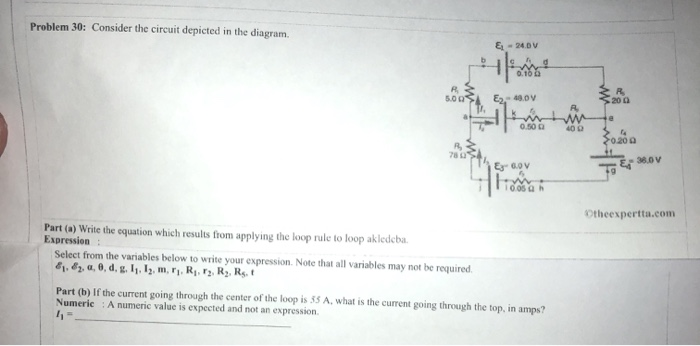
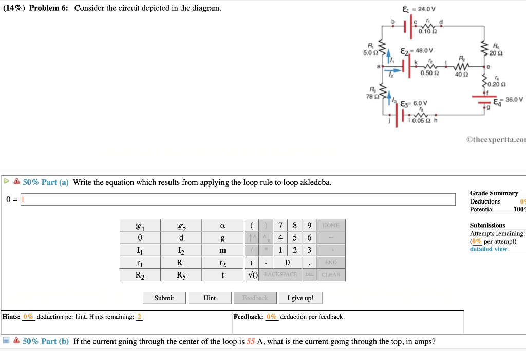
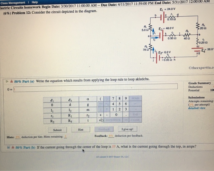
Consider the circuit depicted in the diagram. Transcribed image text: Consider the circuit depicted in the diagram. Write the equation which results from applying the loop rule to loop akledcba. Transcribed image text: (7%) Problem 9: Consider the circuit depicted in the diagram = 24.0 0.10Ω 5.0 Ω Es = 48.0 20Ω 0.50 Ω 40Ω 0.20 Ω 78 Ω ξ3° 6.ov E4 ... An electric potential diagram is a conceptual tool for representing the electric potential difference between several points on an electric circuit. Consider the circuit diagram below and its corresponding electric potential diagram. The circuit shown in the diagram above is powered by a 12-volt energy source. Consider the harmonically driven series LCR circuit shown. V max = 100 V I max =2 mA V Cmax =113 V The current leads generator voltage by 45o L and R are unknown. What is X L, the reactance of the inductor, at this frequency? Electricity & Magnetism Lecture 20, Slide 25
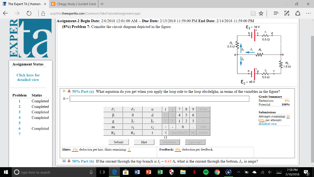
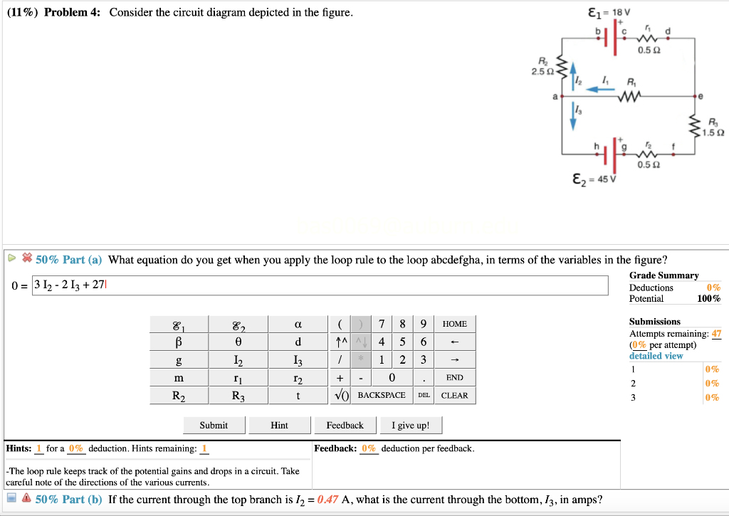
P 5.2-2 Consider the circuit of Figure P 5.2-2. Find i a by simplifying the circuit (using source transformations) to a single-loop circuit so that you need to write only one KVL equation to find i a. Figure P 5.2-2 . Solution: Finally, apply KVL: 16 10 3 4 0 2.19 A aa 3 a 91% (345 ratings) Problem Details. Consider the circuit diagram depicted in the figure. Part (a) What equation do you get when you apply the loop rule to the loop abcdefgha? Part (b) If the current through the top branch is I2 = 0.49 A, what is the current through the bottom I3, in amps? Frequently Asked Questions. Asked for: cell diagram. Strategy: Using the symbols described, write the cell diagram beginning with the oxidation half-reaction on the left. Solution. The anode is the tin strip, and the cathode is the \(\ce{Pt}\) electrode. Beginning on the left with the anode, we indicate the phase boundary between the electrode and the tin solution by a ... ECE124 Digital Circuits and Systerns, Final R.eview, Spring Z0ll [Q1]Forthefollowing clocked sequential circuitwith one input (X)and one output (Z): 1. Drive a state table and draw a state diagram for the circuit. 2. Redesign this circuit by replacing the Qr flip-flop (i.e. the D flip-flop holding Q1 state) with a JK flip- flop, and the Qz flip-flop with a T flip-flop.
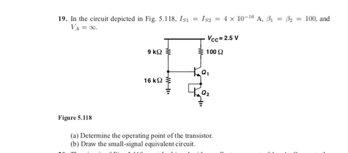
Consider the circuit diagram depicted in the fgure. It is known that two battery internal resistors r1and r2 are both 0.2Ω· = 12V and & = 24V. R2 16Ω 2. and Rs 262, but Ri is unknown. Caution: Current directions. Transcribed image text: (8%) Problem 10: Consider the circuit depicted in the diagram. E-240V 5.00$ 8248.0V RS Ex 6.0V Otheexpertta.com A 50% Part (a) Write ... 1. Obtain the specification of the desired circuit. 2. Derive a state diagram. 3. Derive the corresponding state table. 4. Reduce the number of states if possible. 5. Decide on the number of state variables. 6. Choose the type of flip-flops to be used. 7. Derive the logic expressions needed to implement the circuit. Question: Consider the circuit depicted in the diagram. Write the equation which results from applying the loop rule to loop akebia.
m m 6000 6000 3 16 16 3 v R R v + = ⇒= − (a) The voltage measured by the meter will be 4 volts when R = 6 kΩ. (b) The voltage measured by the meter will be 2 volts when R = 1.2 kΩ. P 4.3-9 Determine the values of the node voltages of the circuit shown in Figure P 4.3-9.. Figure P 4.3-9 . Solution: Express the voltage source voltages as functions of the node voltages to get
Now consider a diagram describing a parallel AC circuit containing a resistor, a capacitor, and an inductor. This time, the voltage across each of these elements of the circuit is the same; on the diagram, it is represented by the vector labeled .
The open-circuit voltage / short-circuit current approach can be used to calculate the Thevenin equivalent for a known circuit. Consider the circuit from slide 4: + - V S R 1 R 2 I S 9V 6 mA 1.5 k! 3 k! Open-circuit voltage - Use whatever method you prefer. We'll use node voltage in this case. + - V S R 1 R 2 I S v a + - v oc YRF= YD ...
Part (i) [3 marks] Consider the circuit depicted in Figure 4. The current source i s is a constant current supply, which is kept in place for a very long time until the switch is opened at time t = 0. Show that the initial capacitor voltage is given by v C(0
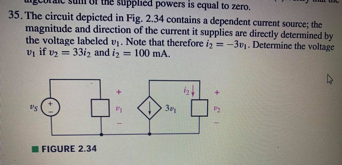
Strategy This circuit is sufficiently complex that the currents cannot be found using Ohm's law and the series-parallel techniques—it is necessary to use Kirchhoff's rules. Currents have been labeled and in the figure, and assumptions have been made about their directions. Locations on the diagram have been labeled with letters a through ...
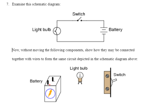
PHY2049: Chapter 27 33 Circuit Problem (1) ÎThe light bulbs in the circuit are identical.What happens when the switch is closed? a) both bulbs go out b) the intensity of both bulbs increases c) the intensity of both bulbs decreases d) nothing changes Before switch closed: V a = 12V because of battery. V b =12 because equal resistance divides 24V in half.

Draw the circuit diagram and assign labels and symbols to all known and unknown quantities. Assign directions to the currents. The direction is arbitrary, but you must adhere to the assigned directions when applying Kirchhoff's rules Apply the junction rule to any junction in the circuit that provides new relationships among
AC circuit containing only an inductor. Consider a circuit containing a pure inductor of inductance L connected across an alternating voltage source (Figure 4.47).The alternating voltage is given by the equation. The alternating current flowing through the inductor induces a self-induced emf or back emf in the circuit.
The electric potential difference of various spots in the circuit may be depicted by using a diagram known as electric potential diagram which is demonstrated underneath. In this illustration, the electric potential at A is = 9V because it's the bigger potential point. The electrical potential at H is = 0V because it is at negative point.
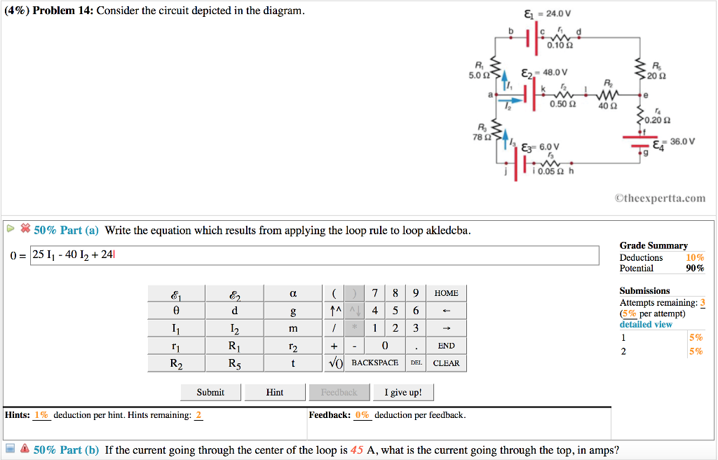
Transcribed image text: & -240V (13%) Problem 6: Consider the circuit depicted in the diagram. R SIE - 48.0V 200 30.200 TE 36.0V Otheexperta.com 50% Part(a) ...

Question: (8%) Problem 12: Consider the circuit depicted in the diagram -24.0 V 0.10Ω Ri 5.0 Ω ε2-48.ov 20 2 0.50 Ω 40Ω 0.20 Ω 78 Ω -36.0 E3 6.0 V lì0.05Ω h ...

Answer to: Consider the circuit diagram depicted in the figure. a. What equation do you get when you apply the loop rule to the abcdefgha, in terms...
Consider the circuit depicted in the diagram. & = 24.0ν Η. 0.10Ω Β, 5.0Ω ε) 48.0ν. a. Write the equation which results from applying the loop rule to loop ...

Consider the circuit diagram depicted in the figure. By a circuit the sum of these potential differences must be zero. Sum the voltage changes across each circuit element around this loop going in the direction of the arrow. Consider the electric circuit shown in the figure. The rectangular boxes in the diagram are the resistors.

Question. Consider the circuit diagram depicted in the figure. What equation do you get when you apply the loop rule to the loop abcdefgha, in terms of the variables in the figure? 0 = If the current through the top branch is I_2 = 0.69 A, what is the current through the bottom, I_3, in amps?
PHY2049Spring2012$ $ Exam2$solutions$ Problem4($ Intheshownfigure,R 1$=R 2$=R 3$=50Ω,$R 4$= 100Ω,andtheideal$batteryhas $ EMF=6V.Whatistheequivalentresistanceof ...
This problem has been solved! Consider the circuit depicted in the diagram. (a) Write the equation which results from applying the loop rule to loop akledcba. (b) If the current going through the center of the loop is 65 A, what is the current going through the top, in amps?
The circuit depicted at the right is an example of the use of both series and parallel connections within the same circuit. ... an understanding of the equivalent resistance of a series circuit can be used to determine the total resistance of the circuit. Consider the following diagrams below. ... Consider the combination circuit in the diagram ...

Consider the circuit diagram depicted in the figure. 0 ω r 3 16. For the action depicted in the figure figure 2 indicate the direction of the induced current in the loop clockwise counterclockwise or zero when seen from the right of the loop. Now consider a diagram describing a parallel ac circuit containing a resistor a capacitor and an inductor.

Transcribed image text: (10%) Problem 5: Consider the circuit diagram depicted in the figure 0.5 Ω R2 2.5 Ω /2 R 1.5Ω 0.5 Ω 50% Part (a) what equation do you get when you apply the loop rule to the loop abcdergha, in terms of the variables in the figure? Grade= 100% Correct Answer Student Final Submission Feedback Correct! 012 R2+ 112 T3 R3 +32-62 0- 1-(Ti +R2) I2+(R3r2)13 2 Grade Summary ...
Consider the circuit below. Since the 4-ohm resistor is in parallel with the capacitor, i(0+) = v C(0+)/4 = 0/4 = 0 A Also, since the 6-ohm resistor is in series with the inductor, v(0+) = 6i L(0+) = 0V. (b) di(0+)/dt = d(v R(0+)/R)/dt = (1/R)dv R(0+)/dt = (1/R)dv C(0+)/dt = (1/4)4/0.25 A/s = 4 A/s v = 6i L or ...
depicted. Rule 2. In circuits which have combinations of L, C & R in SERIES (studied in Module 8) it is customary to draw the phasor representing CURRENT horizontally, and call this the REFERENCE phasor. This is because the current in a series circuit is common to all the components. Rule 3. In parallel circuits, (studied in Module 9) the


0 Response to "41 consider the circuit depicted in the diagram"
Post a Comment