39 mallory ignition wiring diagram unilite
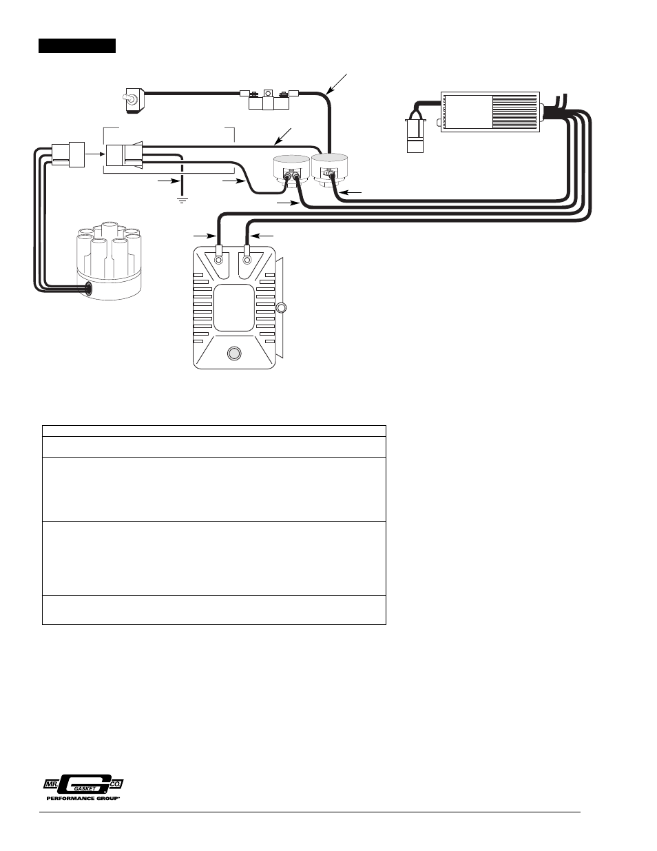
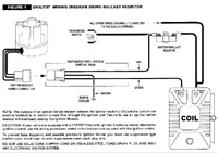
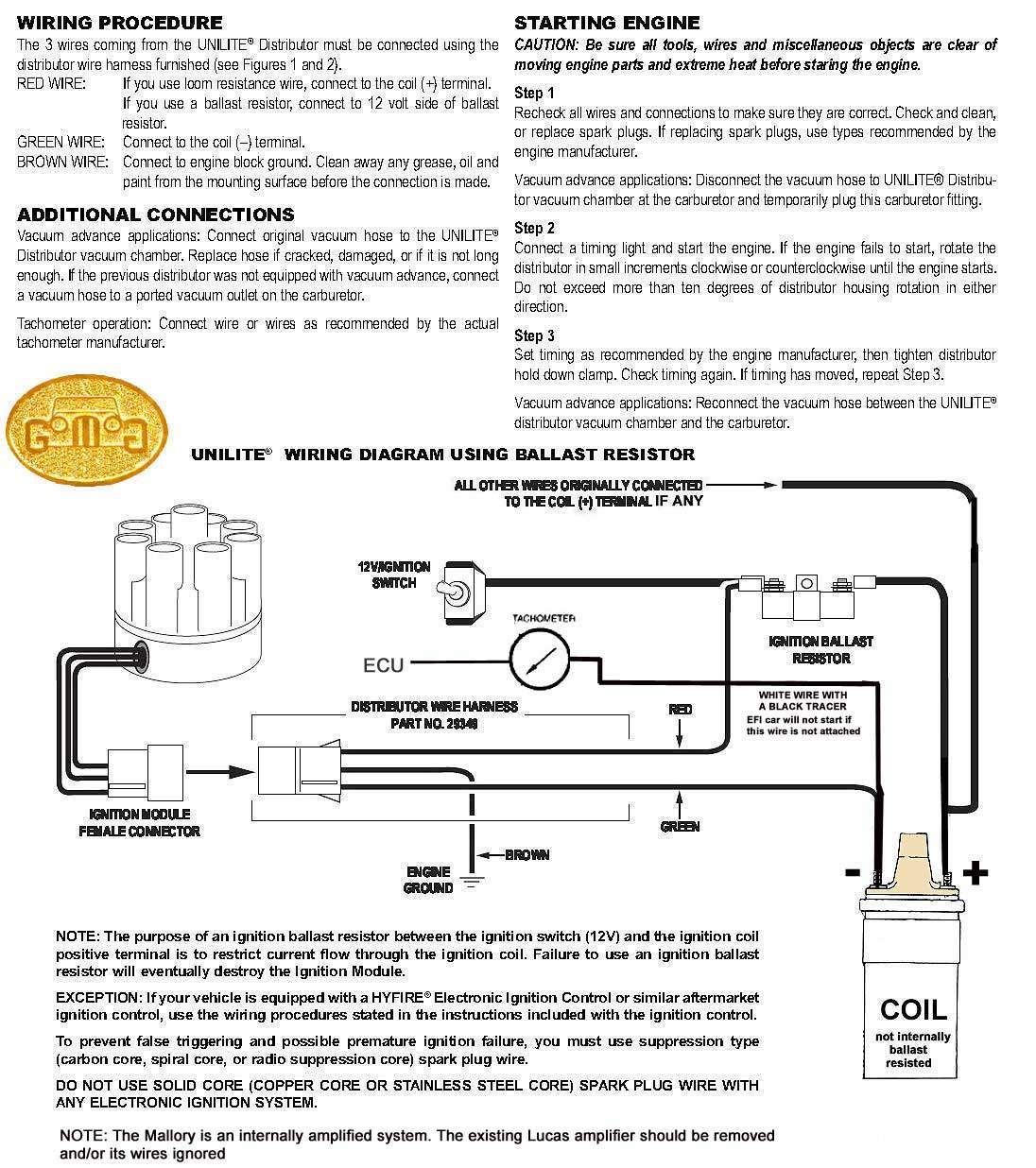
Mallory Ignition Wiring Diagram Harley. 5462 to mallory unilite holley motor life ignition distributor А556 user manual 2 pages coil page 3 13 module a605 1 605 control installation instructions manualzz accel 35496 model 6 29349 wiring harness ballast resistor team camaro tech msd 3748201 replacement parts syangjasandesh com 7 for 1936 69 ... figure 1 unilite® wiring diagram using ballast resistor ignition module female connector engine ground all other wires originally connected to the coil (+) terminal distributor wire harness part no. 29349 ignition ballast resistor pn 8214 brown green red
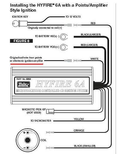
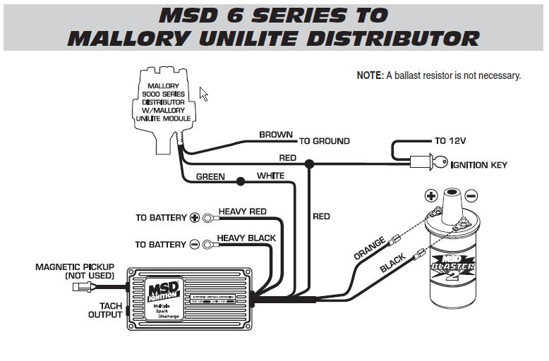
Mallory Unlite For A Rover V8. Mallory comp 9000 wiring diagram points v8wizard pro distributor unilite mg full ignition coil firestorm programmable gm control module 6al edge box resources 220240 instructions catalog 2010 74397g by tmeyer malloryp to unlite for a rover v8 tach chevrolet hei magnetic saab breakerless stereo malloy systems installation proform 390 hyfire electronic replacement ...
Mallory ignition wiring diagram unilite
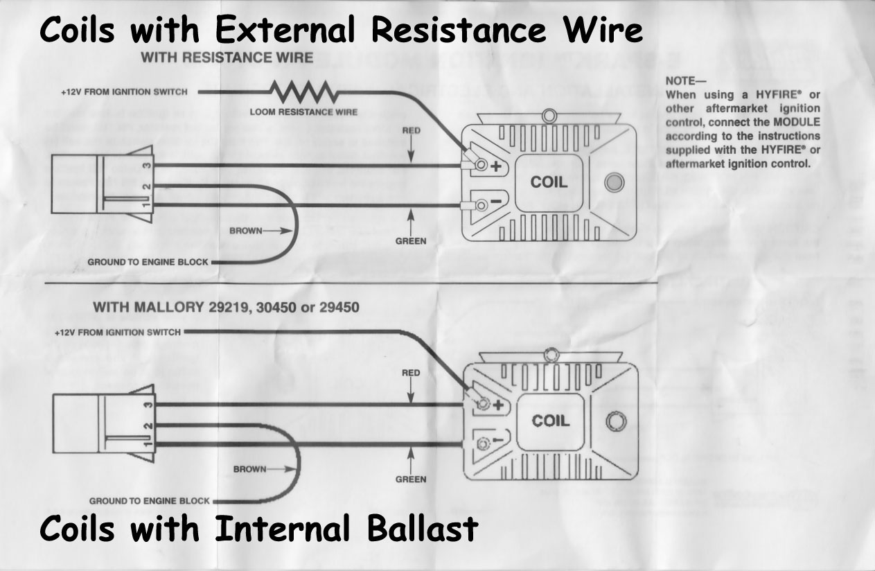
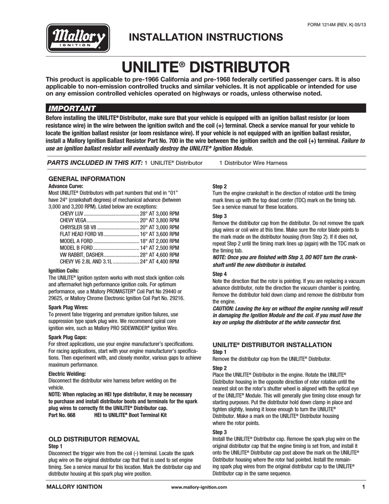
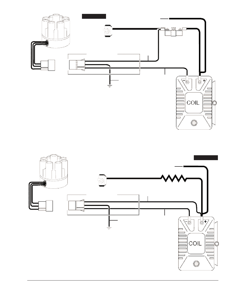
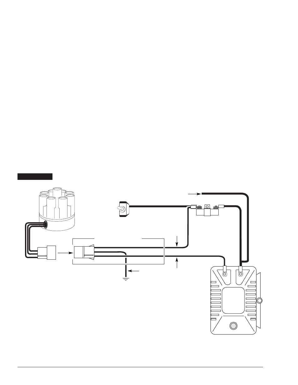
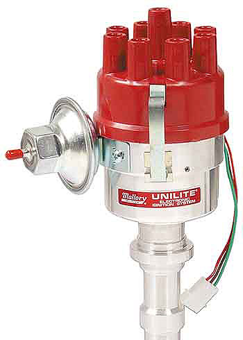
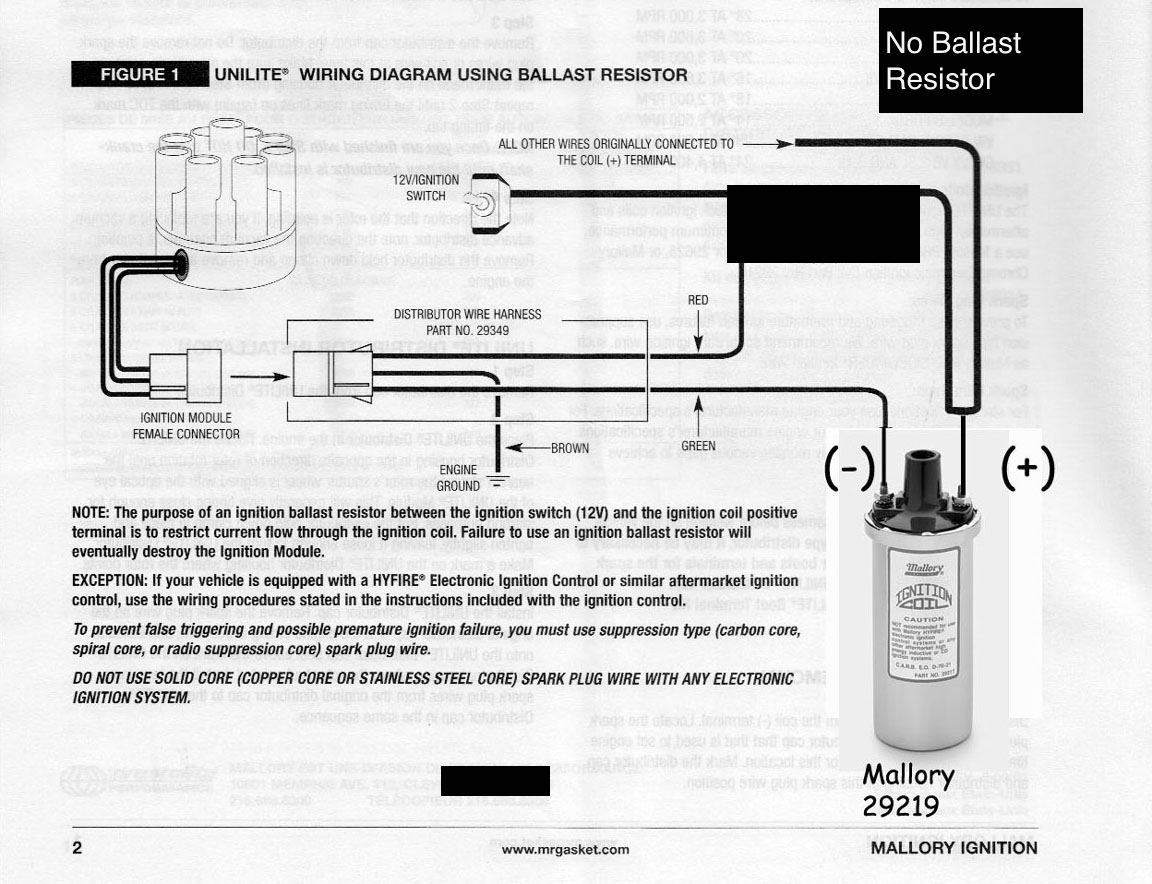
Mallory Ignition Mallory UNILITE DISTRIBUTOR User Manual • Coil • Mallory Ignition For the car. ... WIRING DIAGRAM USING OEM PRIMARY RESISTANCE WIRE. locate the ignition ballast resistor (or loom resistance wire). If your vehicle is not equipped with an ignition ballast resistor, install a Mallory Ignition Ballast Resistor Part No. 700 in the wire between the ignition switch and the coil (+) terminal.Failure to use an ignition ballast resistor will eventually destroy the UNILITE® Ignition ... UNILITE® Distributor vacuum chamber and the carburetor. 2 schematron.org MALLORY IGNITION-+ COIL FIGURE 1 UNILITE® WIRING DIAGRAM USING BALLAST RESISTOR NOTE: The purpose of an ignition ballast resistor between the ignition switch (12V) and the ignition coil positive terminal is to restrict current flow through the ignition coil.
Mallory ignition wiring diagram unilite. Mallory 9000 Wiring Diagram. Unilite, Distributor, Installation instructions • Read online or download PDF • Mallory Ignition Mallory UNILITE DISTRIBUTOR User Manual. spark plug wires from the original distributor cap to the UNILITE. ®. Distributor cap in the same. ground, 12 volt electrical system with a distributor. Msd Ignition Wiring Diagram Diagrams Schematics With Mallory Unilite - discrd.me. discrd.me. Because you like Vehicles. 2 www.mallory-ignition.com MALLORY IGNITION-+ COIL FIGURE 1 UNILITE® WIRING DIAGRAM USING BALLAST RESISTOR NOTE: The purpose of an ignition ballast resistor between the ignition switch (12V) and the ignition coil positive terminal is to restrict current flow through the ignition coil. Failure to use an ignition ballast resistor will Before installing the UNILITE Distributor, make sure that your vehicle is ... Check a service manual for your vehicle to locate the ignition ballas:.4 pages
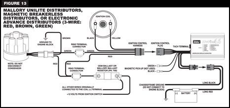
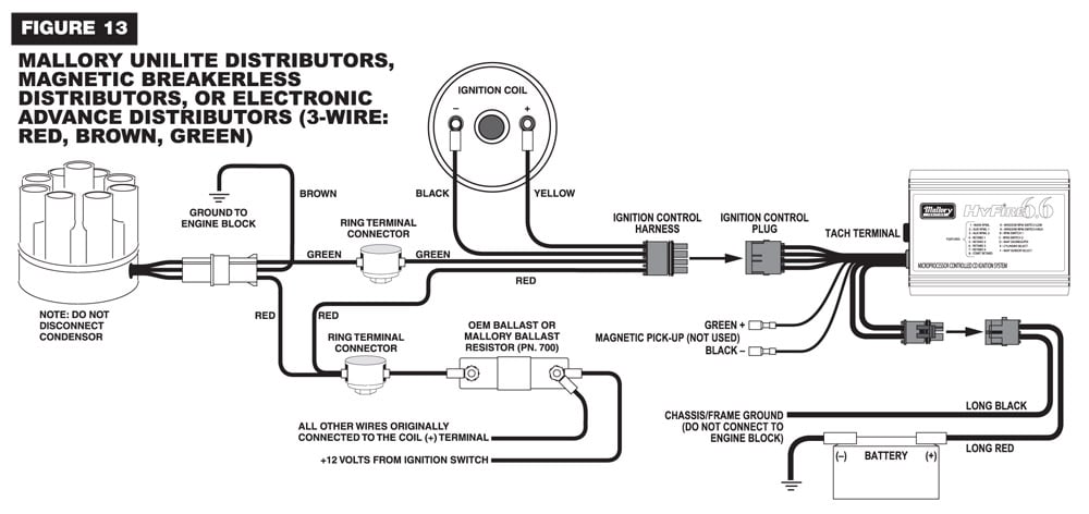
Step 3. Remove the. 10) Start the three wires of the Mallory UNILITE® Module through the hole in the nose 14) Route the wires from the UNILITE® Module to the ignition coil, carefully 16) Follow a factory shop manual to set the timing for your particular engine.Wiring Diagram for Mallory Distributer Don't worry if your coil doesn't look like ... From the thousands of images online concerning mallory ignition wiring diagram, picks the best collections using greatest resolution exclusively for you all, and now this photos is actually considered one of graphics collections in your greatest images gallery regarding Mallory Ignition Wiring Diagram.Lets hope you will want it. This image (Mallory Unilite Wiring Diagram throughout Mallory ... GM HEI Systems/coil-in-cap with OEM module). 4 Mallory Electronic Ignition, UNILITE® Distributors,. Magnetic Installation procedure and diagrams. ignition wire, such as Mallory PRO SIDEWINDER® Ignition Wire. Spark Plug Gaps: NOTE: When replacing an HEI type distributor, it may be necessary to purchase and install . UNILITE® Distributor vacuum chamber and the carburetor. 2 schematron.org MALLORY IGNITION-+ COIL FIGURE 1 UNILITE® WIRING DIAGRAM USING BALLAST RESISTOR NOTE: The purpose of an ignition ballast resistor between the ignition switch (12V) and the ignition coil positive terminal is to restrict current flow through the ignition coil.
locate the ignition ballast resistor (or loom resistance wire). If your vehicle is not equipped with an ignition ballast resistor, install a Mallory Ignition Ballast Resistor Part No. 700 in the wire between the ignition switch and the coil (+) terminal.Failure to use an ignition ballast resistor will eventually destroy the UNILITE® Ignition ... Mallory Ignition Mallory UNILITE DISTRIBUTOR User Manual • Coil • Mallory Ignition For the car. ... WIRING DIAGRAM USING OEM PRIMARY RESISTANCE WIRE.
Coil Mallory Ignition Mallory Unilite Distributor User Manual Page 4 13 Original Mode

Msd 6al Wiring Diagram Mallory Distributor P 9000 Diagram Base Ignition Box Comparison Ignition Box Comparo
Mallory Unlite For A Rover V8
Street Fire Cdi Pn Ground Wire 1 100v 1a Diode Pdf Free Download

Diagram Based Mallory Distributor Wiring Diagram Ignition Coil Distributor Wiring Diagram

Msd 6 Series Installation Instructions 6a 6al 6t 6btm 6tn 6aln Pdf Free Download
Mallory Unilite Users Want To Save Money Nastyz28 Com

Mallory 3755101 Unilite Distributor 1962 80 Ford 221 302
V8wizard

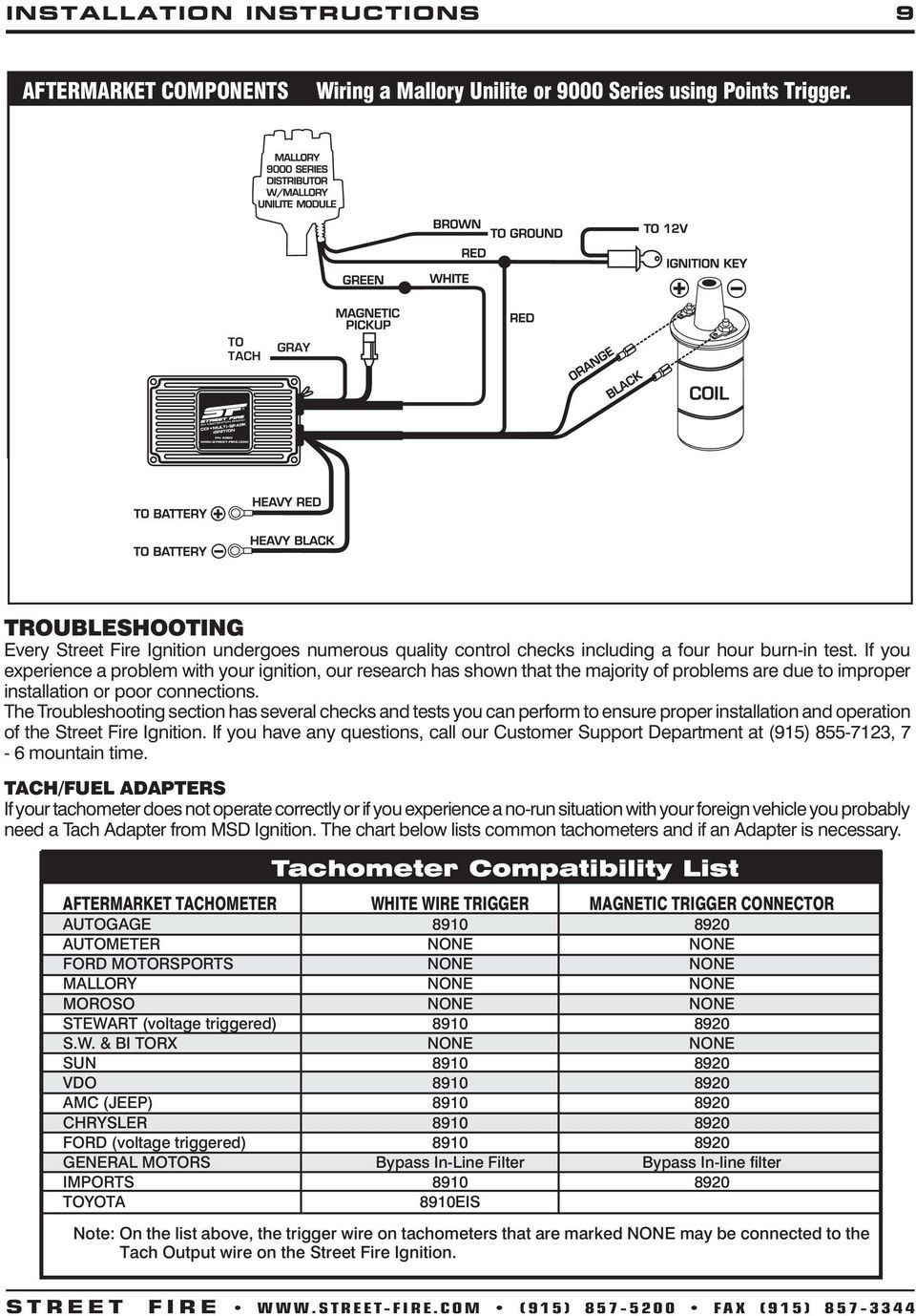
Mallory Tachometer Wiring Diagram Images Nomor Siapa
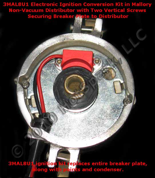
Mallory Electronic Ignition Conversion Kit Hot Spark Com
Nitrous Oxide Installation Zex Perimeter Nitrous Kit Fordmuscle
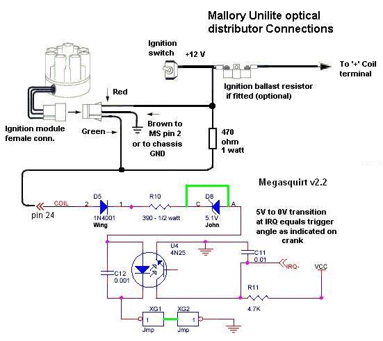
Megasquirt W Unitlite Optical Distributor

Mallory 3727501 Unilite Distributor 1949 53 Flathead Ford
Thesamba Com Performance Engines Transmissions View Topic Mallory Hyfire 6al Issue

Mallory Ignition Question El Camino Central Forum
Thesamba Com Performance Engines Transmissions View Topic Programmable Ignition Type 4 Engine With Stock Cooling
Bob S Studebaker Resource And Information Portal Mallory Unilite Distributor
Mallory Unlite For A Rover V8

Gm 4 Pin Hei Electronic Ignition Control Module Wiring Connections Diagram With A Magnetic Pickup C Ignition Coil Electrical Circuit Diagram Electrical Diagram
Msd 6al Hookup Question Pontiac Gto Forum
Mallory Unilite Distributor Installation Instructions Manualzz

Does Not Shut Off The Amc Forum Page 2
Need Help No Spark For A Bodies Only Mopar Forum

Unilite Wiring Diagram Ezo Rock101

Australian Rr Forums Installing A Replacement Distributor Mallory Unilite
Mallory Ignition Mallory Unilite Electronic Breakerless Conversion Kit 561 562 563 User Manual Page 3 4 Original Mode Also For Mallory Unilite Electronic Breakerless Conversion Kit 558 559 560
Hei Conversion

Megasquirt W Unitlite Optical Distributor
Coil Mallory Ignition Mallory Unilite Distributor User Manual Page 2 13 Original Mode
Mallory Unlite For A Rover V8
Mallory Ignition 29371 Mallory Circuit Guards Summit Racing
Bob S Studebaker Resource And Information Portal Mallory Unilite Distributor

Mallory 29349 Distributor Wiring Harness
Nitrous Oxide Installation Zex Perimeter Nitrous Kit Fordmuscle
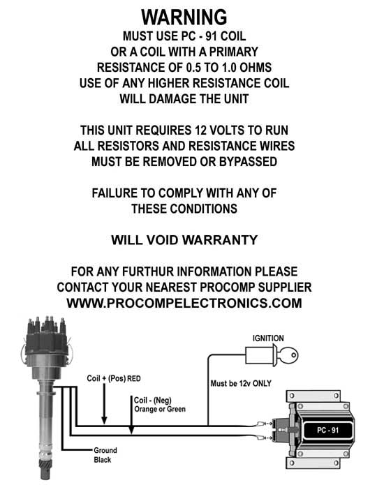
Wiring A Procomp Billet Distributor 3 Wires Moparts Forums
Mallory Ignition Diagram

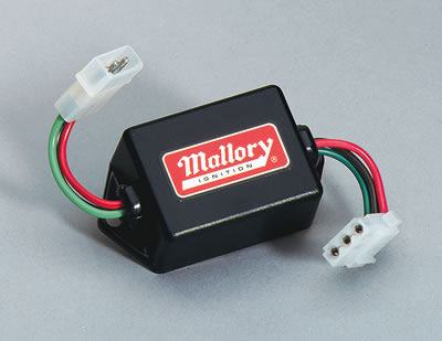
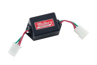
Mallory Unilite Module Power Filter Protection System 29351 Aircooled Net Vw Parts

Msd 7al 2 Ignition Pn 7220 7224 7226 Pdf Free Download
0 Response to "39 mallory ignition wiring diagram unilite"
Post a Comment