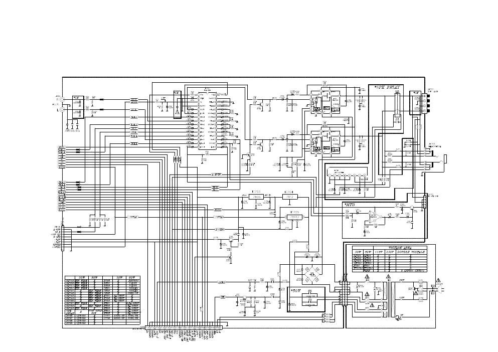
42 limitorque l120 wiring diagram
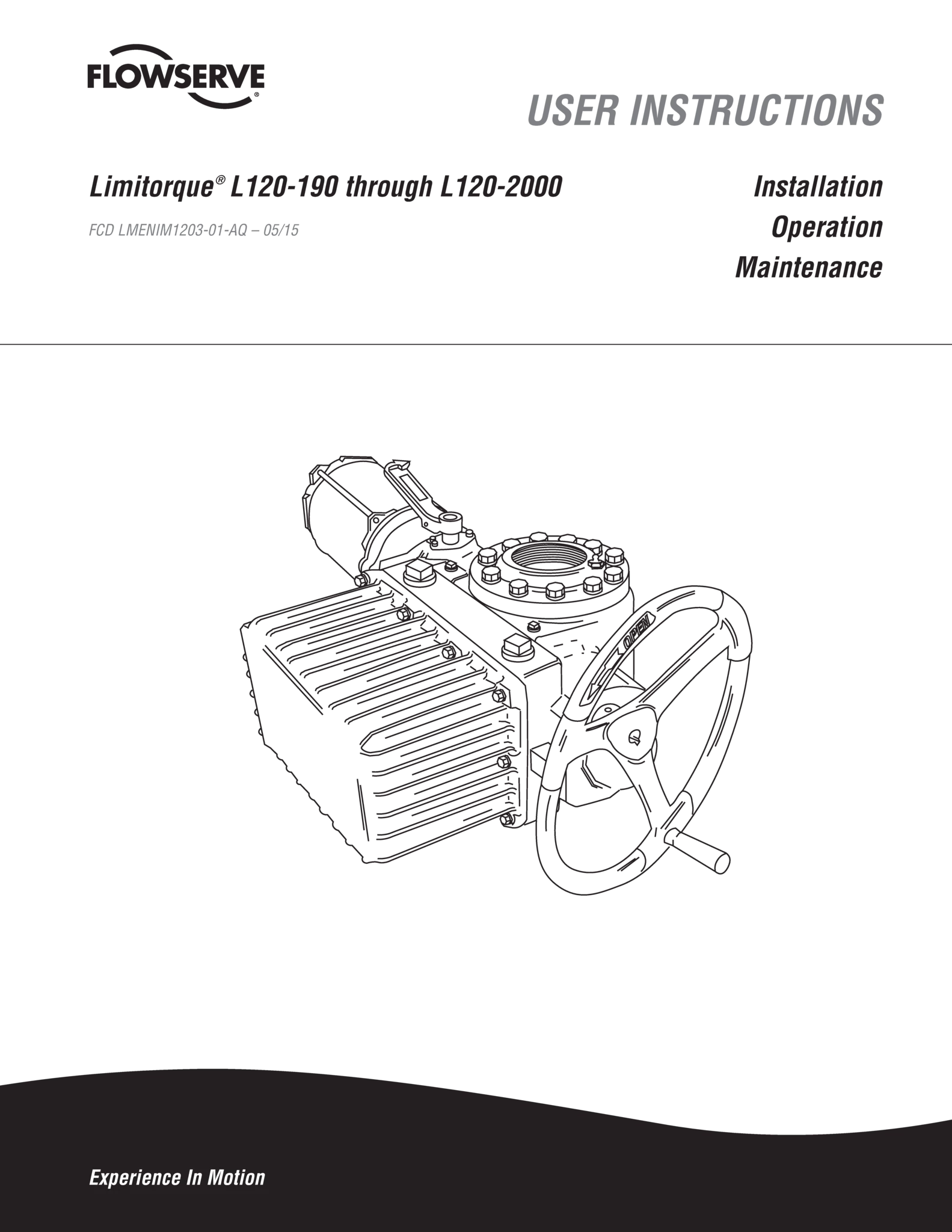
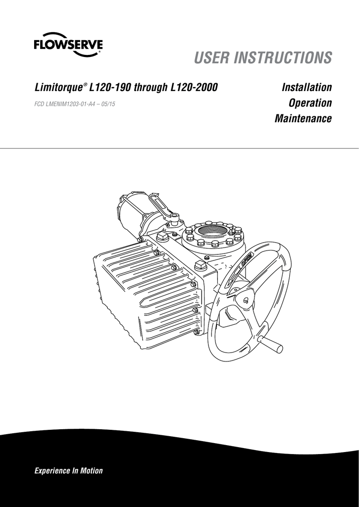
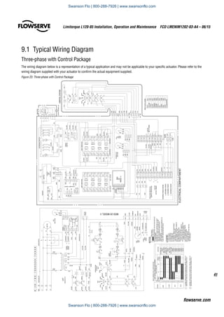
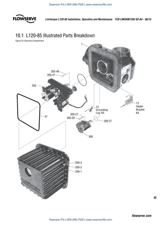
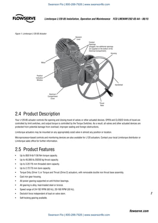
Limitorque L120 Wiring Diagram - schematron.org Mar 27, 2019 · Wiring Diagram Pictures Limitorque L120 Wiring Diagram 27.03.2019 3 Comments stances, Limitorque's L actuators are ideal for valves requiring rotary Flowserve Limitorque L series multi-turn electric actuators See wiring diagram. Limitorque® L through L FCD LMENIMA4 – 05/ 2 .. Consult the relevant wiring diagram for limit switch contact development. USER INSTRUCTIONS - Chalmers & Kubeck Place the L120 actuator in manual mode. 2. Release the load on the wormshaft spring pack. 3. For open and close directions, loosen Screw (A) and move Pointer (B) to desired position. A higher number indicates a high torque and/or thrust output. 4. Tighten Screw (A). 5. Operate the valve electrically to seat valve and to ensure tight shutoff. 6.
L120 NCU Wiring Diagram - Flowserve L120 NCU Wiring Diagram. Drawing Number. Description. Unit Size. 17-499-0009-3. 3ph Optional Potentiometer. 17-499-0015-3. 3ph Optional Potentiometer SW323. 17-499-0029-3.
Limitorque l120 wiring diagram
Limitorque L120 Wiring Diagram Sample - Wiring Diagram Sample May 01, 2019 · limitorque l120 wiring diagram – What is a Wiring Diagram? A wiring diagram is a simple visual representation of the physical connections and physical layout of your electrical system or circuit. It shows how a electrical wires are interconnected and will also show where fixtures and components may be attached to the system. L120 BIC Wiring Diagram - Flowserve Limitorque® DRAWINGS BY CATEGORY; L120 BIC Wiring Diagram; L120 BIC Wiring Diagram. Drawing Number Description Unit Size; 17-499-0005-3: 3ph Potentiometer: 17-499 ... Limitorque L120-20 Wiring Diagram - schematron.org Jan 09, 2018 · Limitorque L120-20 Wiring Diagram 01.09.2018 4 Comments Limitorque Actuation Systems L Series FCD LMENIMA4 – 05/ 2 Declutch Assembly (L/40) (Refer to Figure ) . Verify all actuator wiring is in accordance with the applicable wiring diagram, national and local.
Limitorque l120 wiring diagram. L-120 SERIES INSTRUCTION AND MAINTENANCE ... - Limitorque India CASE-I:-Trip contacts/end position contact is Consult the relevant wiring diagram for limit switch contact closed (Generally required if UEC-3 family (fig-2) development. All L120 units are supplied with 8 contact limit controller is supplied) switches-4 switches on each of 2 rotors. Limitorque L120 Wiring Diagram Oct 12, 2018 · Limitorque L120 Wiring Diagram Limitorque Actuation Systems L Series FCD LMENIMA4 – 05/ 2 . Verify all actuator wiring is in accordance with the applicable wiring diagram. E September Limitorque L Series Installation & Maintenance Volt Torque Switch Figure – L through 40 typical wiring diagram Figure 5. Limitorque L120-20 Wiring Diagram - schematron.org Jan 09, 2018 · Limitorque L120-20 Wiring Diagram 01.09.2018 4 Comments Limitorque Actuation Systems L Series FCD LMENIMA4 – 05/ 2 Declutch Assembly (L/40) (Refer to Figure ) . Verify all actuator wiring is in accordance with the applicable wiring diagram, national and local. L120 BIC Wiring Diagram - Flowserve Limitorque® DRAWINGS BY CATEGORY; L120 BIC Wiring Diagram; L120 BIC Wiring Diagram. Drawing Number Description Unit Size; 17-499-0005-3: 3ph Potentiometer: 17-499 ...
Limitorque L120 Wiring Diagram Sample - Wiring Diagram Sample May 01, 2019 · limitorque l120 wiring diagram – What is a Wiring Diagram? A wiring diagram is a simple visual representation of the physical connections and physical layout of your electrical system or circuit. It shows how a electrical wires are interconnected and will also show where fixtures and components may be attached to the system.

__84571.1590694773.jpg?c=2&imbypass=on&imbypass=on)











0 Response to "42 limitorque l120 wiring diagram"
Post a Comment