42 audio signal flow diagram
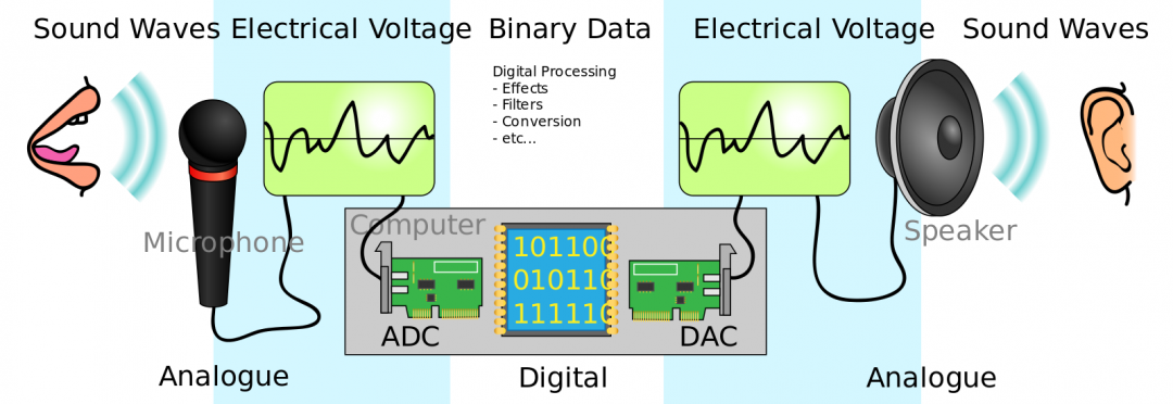
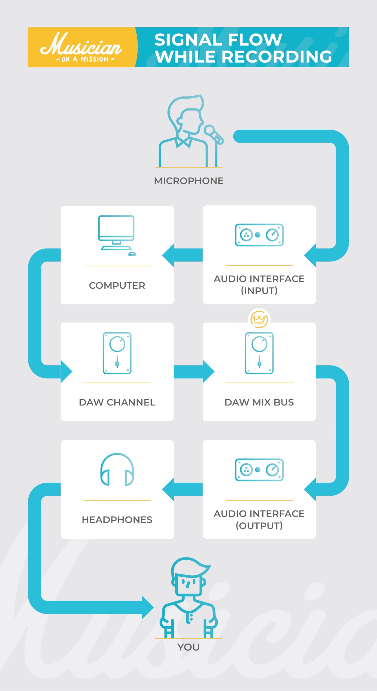
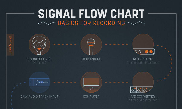
Downloadable Charts to Understand Audio Signal Flow in a DAW The recording signal flow Download Recording Chart Two facts of supreme importance to keep in mind: 1. The mic preamp is before the A/D converter. So, set your recording level via the mic preamp. If you cause distortion by overloading the A/D converter, turning down the track fader won't fix the distortion problem. 2. Signal Flow - Signature Sound Signal flow begins at the sound source, with a transduction stage. Transduction is the process of converting one type of energy into another form of energy. Within our diagram, the microphone (s) take the sound waves from the sound source and convert the sound waves into an electric current (through the process of transduction).
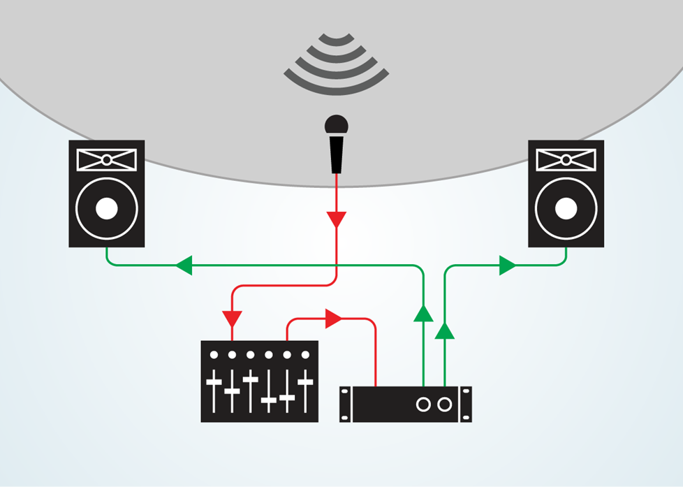
Live Sound Explained: 3. The PA System (Signal Flow ... Signal flow refers to the path that electronic signals follow through the components of a PA system. This article is organized to follow that path from the input devices to the output devices and through all of the stages in between. The following diagram illustrates the signal flow through a typical sound system, as described in this article.

Audio signal flow diagram
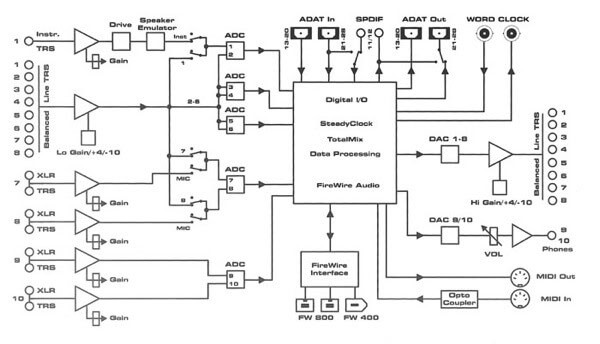
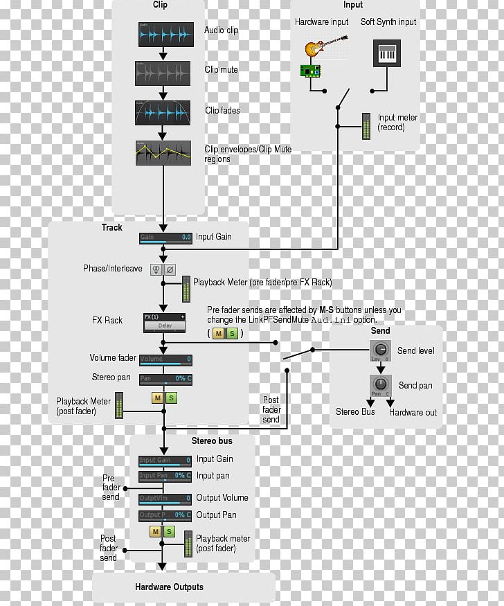
FAQ/Knowledge Base - Acoustica Mixcraft's audio signal flow Mixcraft's audio signal flow. Last updated: January 2nd, 2020. Category: Tips. Here is the path that audio follows in Mixcraft 9: Clip (including any clip automation). Fader Send - Dry; Gain (Mixer) Compressor (Mixer) Drive (Mixer) 3-Band EQ (Mixer) ... Audio Visual Design & Drawing Software | AV Proposal ... XTEN-AV Designer generates automated block schematics, rack layouts, ceiling speakers layouts, signal flow diagrams, cable schedules and scope of work documents. Edit auto-generated drawings and convert to other formats such as AutoCad and Visio. Project Design Mixing: Flow charts and Block diagrams - Lenard Audio Flow charts also show what parts of the mixer can be externally accessed or separated, and which parts are not accessible. (a) Balanced Inputs The example flow chart below, of a single channel shows that the input can be selected for a balanced XLR mic or a line level jack plug. Balanced means that the mic signal is between XLR pins (2 and 3 ...
Audio signal flow diagram. Audio Theory - Console Signal Flow - YouTube For helpful Church Technology resources check outEllisProMedia.comwww.facebook.com/EllisProMediawww.instagram.com/ellispromediaIn this video we are going to ... Using Excel to draw signal flow charts - Sweetwater I have not attached my Excel flow diagram of a simple audio reinforcement system I designed for our auditorium here at the DOC (Department Of Commerce) because Audioforums.com does not seem support Microsoft Excel Worksheet files for up load. but here is the PDF I hope someone finds this information useful. Cheers!:D byjus.com › jee › communication-systemsCommunication Systems - Block Diagram, Types, Elements ... A repeater receives the transmitted signal, amplifies it and send it to the next repeater without distorting the original signal. Block Diagram of Communication Systems The block diagram given below represents the flow of the signal from the source to the destination. Radio - Wikipedia See diagram. The information in a radio ... in FM the frequency of the radio carrier signal is varied slightly by the audio signal. FM broadcasting is permitted in the FM broadcast bands between about 65 and 108 MHz in the very high frequency (VHF) range. Radio waves in this band travel by line-of-sight so FM reception is limited by the visual horizon to about 30–40 mi …
Documenting AV Setups and Signal Flow? : CommercialAV level 2. · 5 yr. ago. I'd like to note here that AVSnap is the only diagramming software that actually allows you to sanity check your hookups and allows you to build a BOM and connector/wire list. And it's free. And you can write entire control interfaces for TCP, UDP and Serial devices in the same document. System signal flow diagram [classic] | Creately System signal flow diagram [classic] by André. Edit this Template. Use Creately's easy online diagram editor to edit this diagram, collaborate with others and export results to multiple image formats. Shows how the internal signals is connected. block basic abstract. From Source to Output: Audio Signal Flow for ... - Videomaker Signal Flow Chart Audio routing is built on a set of stages that follow a sound all the way from its source, input and conversion, channel strip, output stage and ultimately through the speaker and into your ears. Signal Flow - How it works I hope you had a good look at the previous diagram. Push-Pull Amplifier Circuit - Circuit Digest 13/08/2018 · The stages of the Class A amplifier allows same amount of load current to flow through it even when there is not input signal connected, therefore large heatsinks are needed for the output transistors. The circuit diagram for Class A amplifier is given below: Class B Amplifier. Class B amplifier is the actual Push-Pull Amplifier. Efficiency of Class B amplifier is higher than …
Signal Flow Chart Live Sound [classic] | Creately Signal Flow Chart Live Sound [classic] | Creately Signal Flow Chart Live Sound [classic] by Jody Bromley Edit this Template Use Creately's easy online diagram editor to edit this diagram, collaborate with others and export results to multiple image formats. You can edit this template and create your own diagram. AV Inputs & Outputs - Understanding the Flow of Signals ... Understanding the flow of signals within your home theatre starts with becoming familiar with the three distinct types of devices that your home entertainment components fall into: Source Devices, Hub Devices & Sink Devices. Source Devices are easy to identify as they generally only have AV Outputs - they play your media and send the audio and ... Understanding Audio Channel Signal Flow in Cubase 8 : Ask ... The signal flow of an audio channel is identical to any audio-based channel, including VST Instruments, ReWire, Groups, and the Stereo (or multi-channel) Output. The only difference is the Stereo Output Channel, for it lacks the Sends section found on all the other channel types. With that in mind, be aware that all these channels have ... PDF SIGNAL FLOW CHART - iZotope HARD DRIVE /SSD /FLASH DRIVE DAW AUDIO TRACK FADER DAW AUDIO TRACK PAN (where audio les are recorded) DAW AUDIO TRACK INPUT COMPUTER A/D CONVERTER (in the audio interface) MIC PREAMP (in the audio interface) SOUND SOURCE MICROPHONE (vocalist) SIGNAL FLOW CHART. Title: signal-flow-chart-printer-friendly-recording
The Recording Studio Signal Flow Explained
Class C power amplifier circuit diagram and theory. Output ... 09/01/2014 · Due to the huge amounts of distortion, the Class C configurations are not used in audio applications. The most common application of the Class C amplifier is the RF (radio frequency) circuits like RF oscillator, RF amplifier etc where there are additional tuned circuits for retrieving the original input signal from the pulsed output of the Class C amplifier and so the …

Miniclone - Eurorack Signal Flow Transparent PNG - 1024x912 ...
The Recording Studio Signal Flow Explained A step by step walk through the diagram 1. Microphone->Mic Preamp The microphone picks up the sound, and a mic level signal is sent to the microphone preamp. Since mic level signals are inherently weak, the preamp is needed to amplify it to a higher level. The amplified signal is known as line level. 2. Mic Preamp->Hardware Effects
Overview and signal flow
PDF Section 2 Block Diagrams & Signal Flow Graphs Signals- inputs and outputs of blocks -signal direction indicated by arrows -could be voltage, velocity, force, etc. Summing junctions-points were signals are algebraically summed - subtraction indicated by a negative sign near where the signal joins the summing junction K. Webb MAE 4421 4 Standard Block Diagram Forms

A block diagram of the components of the system and the audio ...
Signal Flow on the App Store Signal Flow is the cloud based virtual tool that all Audio Engineers will love. Easily create and share input lists and stage plots with your entire team. Featuring offline data sync, live global changes, unlimited stage plot creations and so much more. Say goodbye to hand drawn stage plots and outd…

FlowDiagram shows signal flow graphically - Cubase ...
PDF MX-1 Audio Signalflow Diagram - Roland Corporation mono channel input 1-4 stereo channel input 5/6 digital channel digital in usb channel usb host 1-4 pc channel analog in pc audio in (from hi-speed usb) pc audio in

Encyclopedia of Home Recording: Signal Flow
2004 Ford F-150 fuse box diagram - StartMyCar 2004 Ford F-150 fuse box diagram. The 2004 Ford F-150 has 3 different fuse boxes: Passenger compartment fuse panel / power distribution box diagram. Auxiliary relay box (with DRL) diagram. Auxiliary relay box (without DRL) diagram * Ford F-150 fuse box diagrams change across years, pick the right year of your vehicle: Type No. Description; Fuse MINI . 10A: 1: …

Home Recording Studio 101: Audio Signal Flow ...
Analog Recording Signal Flow (Diagrams + How Does It Work?) It allows you to place an effects unit or signal processor (such as a compressor) into the signal chain. You would need to physically route this out of the insert, into your effect and then back into the signal chain. This is often done via a patch bay or through points on the channel strip in smaller mixers. EQ
Audio Signal Flow: The Ins and Outs - Produce Like A Pro
Understanding Signal Flow - SoundSessions The channel strip tends to lay out generally "in order" as it applies to the audio signal flow - Gain, then EQ, then the Fader, for example. But this is a very broad overview. There is much more detail to be learned. So how do you learn the signal flow of your paticular console? You break out the manual.
Crystal Sound story and RE/P article
Audio Signal Flow: What It Is and How to Use It What Is Signal Flow? Signal flow is the order of operations a sound goes through. When you record an instrument, the sound goes through different stages before you hear it through the speakers. Signal flow is the list of steps that sound goes through in order for you to hear it. It's kind of like riding a train. Say you're trying to get downtown.

Home Recording Studio 101: Audio Signal Flow ...
Chevrolet Silverado, GMC Sierra (2003-2006) Fuse Diagram ... Fuse box diagram (fuse layout), location and assignment of fuses and relays Chevrolet Silverado and GMC Sierra 1500, 2500, 3500 (2003-2006).
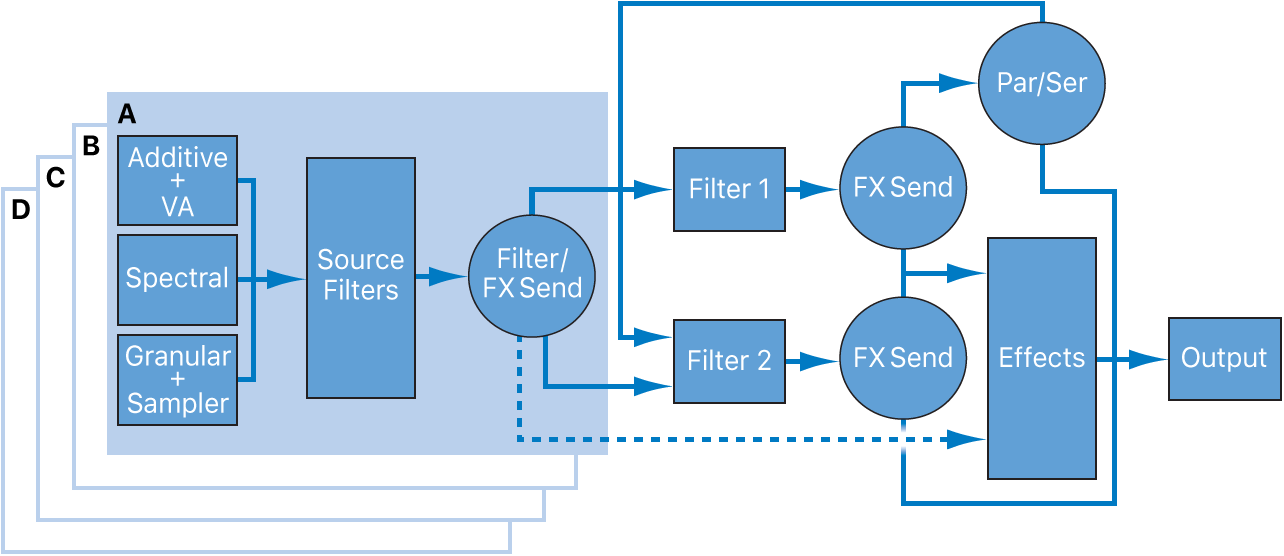
Alchemy overview in Logic Pro - Apple Support (MD)
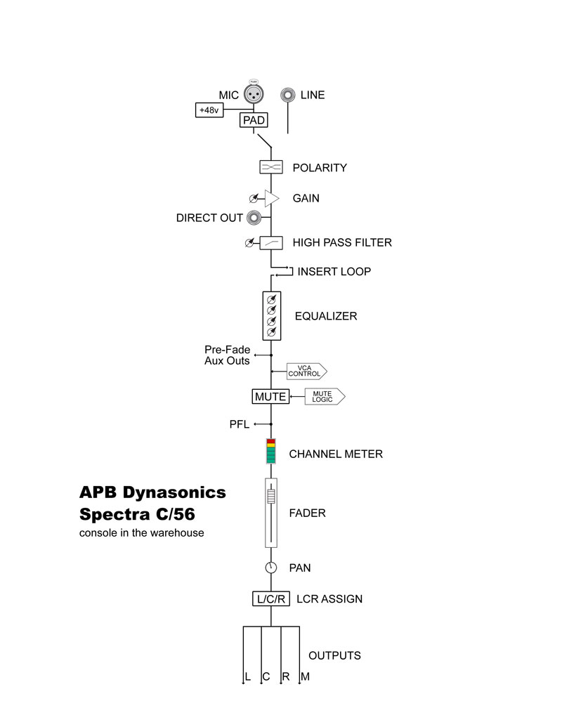
Mastering Signal Flow - Here it Comes and There it Goes ... From the signal input, it usually follows as such; Gain control (controls how much of the signal you are letting into the system) Insert loop (plugs in back of mixer for auxiliary effects) High-pass filter (used to cut out frequencies below a fixed point) Equalizer Channel on/off or mute switch Fader Pan control (for stereo panning)
Church Sound: Signal Flow & Console Operation - ProSoundWeb
Electronic circuits schematics diagram for free Electronic circuits schematics diagram for free : Amplifiers: 100W amplifier 10W amplifier ... Signal generator: S meter: Sound pressure level meter: S pectrum analyzer : SWR Power Meter: Tachometer . TDR cable reflection tester: Thermometer: Tone Generator. Transistor Tester: UTP Cable Tester: Wattmeter: Wire tracer : Motor : AC motor speed controller: DC motor speed …

Signal Flow - Signature Sound
The Ins and Out of Audio Signal Paths - Live Sound Education In this diagram you can see that you have a choice of two inputs, like on most standard mixers. MIC input as standard receives a 5mV signal from a microphone. The LINE input generally receives around 1 Volt. In order to deal with this, the mixer will have microphone PREAMPS in order to boost the MIC voltage to match the LINE level.

How to Use Matrix Mixing | GearCast - Full Compass Systems
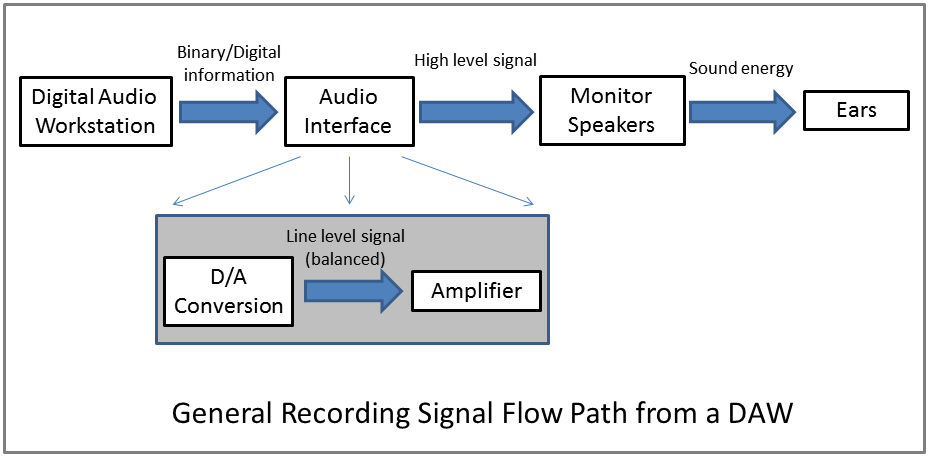
Understanding Audio Signal Flow in Recording Studio Result: Audio is in our DAW: At this stage, our signal has flowed from its origin as a physical sound to a pre-amp and then to an A/D converter which sends the resulting digital audio to our PC. Out. The next step of the signal flow is similar to the first but in reverse.
Csound Journal
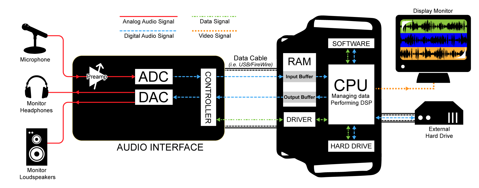
HD Audio System Block Diagram - Optimal Sound HD Audio System Block Diagram. To date the signal flow of the typical PC has been poorly understood even by the engineers working on it. Until the publication of this block diagram, this information was not available as a whole, especially when viewed as an entire system including software and hardware.
Audio Signal Flow: What It Is and How to Use It
Fuse box diagram Ford F-150 2009-2013 Audio Digital Signal Processing (DSP) module. F65. 20. Power point, instrument panel. F66. 20. Power point, console 1 – with floor shifter. F67 – Not used. F68. 20. Transfer Case Control Module (TCCM) F69. 30. Dual Climate Controlled Seat Module (DCSM), Heated seat module. F70 – Not used. F71 – Not used. F72. 20

Signal Flow #audioengineering #recording #musicproduction ...
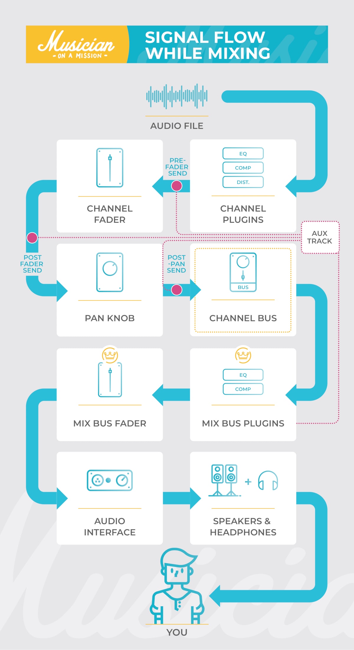
The Signal Flow in Ableton Live Incl. Free Wallpaper ... Then it takes the audio from the output of the set track as an input, while the rest remains the same. If you're using the Sends, the signal path depends on the Pre/Post Toggle setting for each that you can find in the Session View in the Master track parallel to the Send dials. Pre and post is short for pre fader and post fader.

Signal Flow - Signature Sound
Basic CCTV System Diagram. CCTV Network Diagram Example ... ConceptDraw DIAGRAM enhanced with Audio, Video, Media solution is a helpful tool for illustration of a CCTV network. It contains library of vector cliparts of video and TV devices and different digital gadgets for drawing such illustrations Simple Diagramming. Create flowcharts, org charts, floor plans, business diagrams and more with ConceptDraw DIAGRAM. Audio and …

Audio Signal Flow: What It Is and How to Use It
› ford › f-1502008 Ford F-150 fuse box diagram - StartMyCar 2008 Ford F-150 fuse box diagram. ... Delayed accessory power for audio, power door lock switch and moon roof switch illumination ... Heated Exhaust Gas Oxygen (HEGO ...
Live Sound Buying Guide
fusesdiagram.com › chevrolet › fuse-box-diagramFuse box diagram Chevrolet Silverado 2008 Marker Lamp – RF (Z88), Park/Turn Signal Lamp – RF Upper, Park/Turn Signal Lamp – RF Lower, Tail/Stop and Turn Signal Lamp – Lower Right, Tail/Stop and Turn Signal Lamp – Lower Right, Marker Lamp – RR (Z88), License Lamp – Right, Clearance Lamp – RF (R05), Clearance Lamp – RR (R05), Marker Lamp – Tailgate . 27. FOG LAMP Fuse ...
5.1.4 Signal Path in an Audio Recording System – Digital ...
fuseandrelay.com › honda › civicFuse box diagram Honda Civic 8G and relay with assignment and ... May 08, 2021 · 10A Alternator, Engine Control Module (ECM / PCM), EVAP (Mass Air Flow (MAF) Sensor) 10A DC-DC converter, electrical load sensor (ELD), petrol vapor recovery (EVAP), mass air flow (MAF) sensor, engine and transmission control unit (PCM), brake pedal position sensor, secondary heated oxygen sensor (HO2S) 4

Mixing Tips: Know Your Signal Flow in SONAR
Low Latency Audio - Windows drivers | Microsoft Docs 14/12/2021 · Delay between the time that a user taps the screen until the time that the signal is sent to the application. Touch-to-sound latency: Delay between the time that a user taps the screen, the event goes to the application and a sound is heard via the speakers. It is equal to render latency + touch-to-app latency. Windows Audio Stack. The following diagram shows …

PreSonus Studio One DAW signal flow diagram. It's important ...
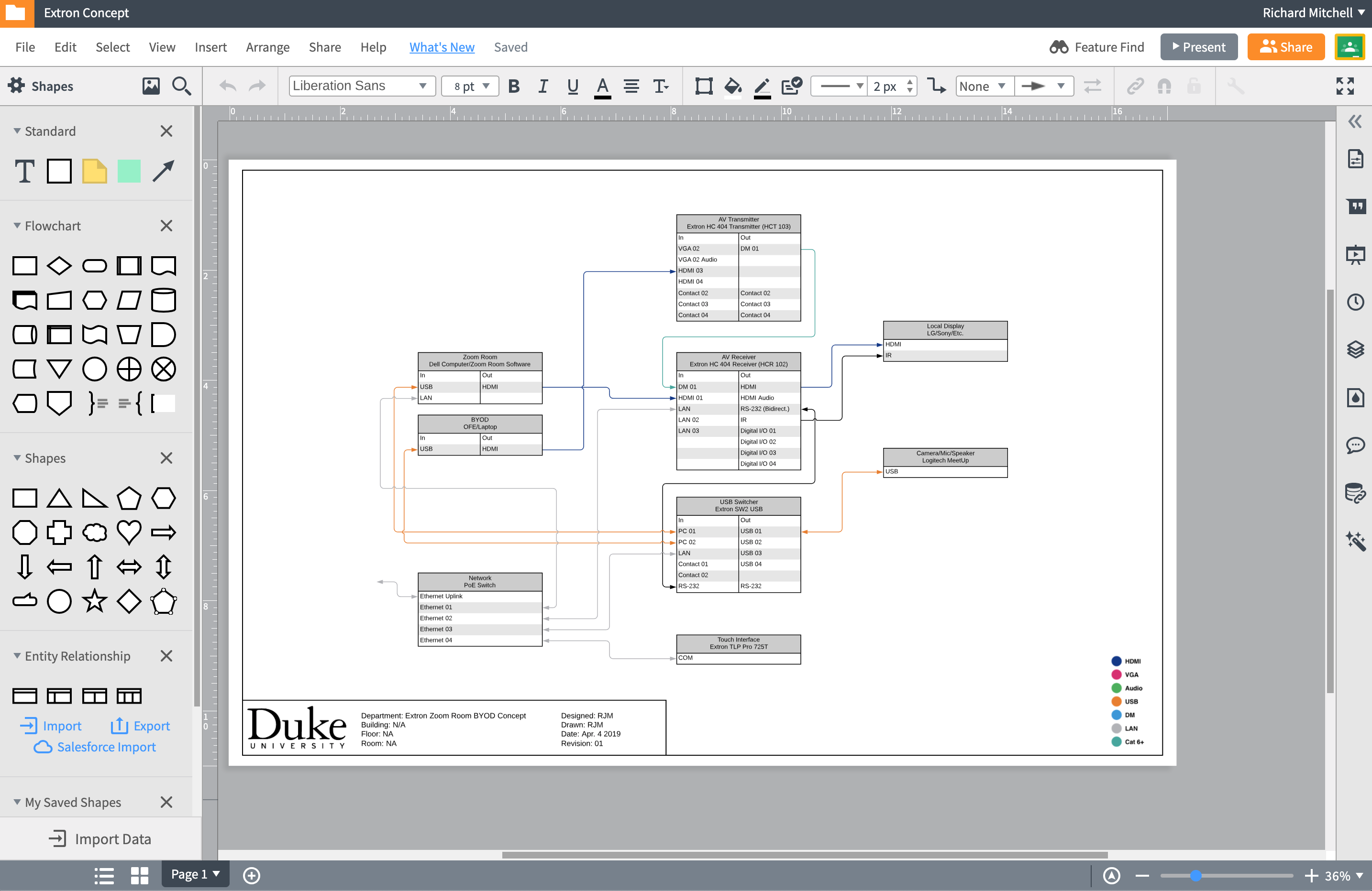
Quick AV Signal Flow with Lucidchart | DDMC First, what is a signal flow diagram, and why do I need it? A signal flow diagram shows the signal path (audio, video, network, control, etc.) from inputs to outputs, for the entire AV system. It's essentially a blueprint for the system… and would you buy a house where they didn't have a blueprint?
OT: Audio Signal Flow diagram standards?
AN5027 Application note - STMicroelectronics digital signal. The STM32 MCUs and MPUs acquire digital data from the microphone(s) through particular pe ripherals to be pr ocessed and transformed into data standard for aud io. The audio data is then handled by the microcontroller according to the targeted audio application. Figure 1. Example of sound acquisition in audio application. a. Arm ...
Audio signal flow - Wikipedia
Audio signal flow - Wikipedia Audio signal flow is the path an audio signal takes from source to output. The concept of audio signal flow is closely related to the concept of audio gain staging; each component in the signal flow can be thought of as a gain stage . In typical home stereo systems, the signal flow is usually short and simple, with only a few components.
Signal Flow – Multimedia Studies 172
Mixing: Flow charts and Block diagrams - Lenard Audio Flow charts also show what parts of the mixer can be externally accessed or separated, and which parts are not accessible. (a) Balanced Inputs The example flow chart below, of a single channel shows that the input can be selected for a balanced XLR mic or a line level jack plug. Balanced means that the mic signal is between XLR pins (2 and 3 ...

Signal Flow Diagrams | Acid Pro
Audio Visual Design & Drawing Software | AV Proposal ... XTEN-AV Designer generates automated block schematics, rack layouts, ceiling speakers layouts, signal flow diagrams, cable schedules and scope of work documents. Edit auto-generated drawings and convert to other formats such as AutoCad and Visio. Project Design

Module 1.4 – Dolby Atmos Content Creation Signal Flow – Dolby ...
FAQ/Knowledge Base - Acoustica Mixcraft's audio signal flow Mixcraft's audio signal flow. Last updated: January 2nd, 2020. Category: Tips. Here is the path that audio follows in Mixcraft 9: Clip (including any clip automation). Fader Send - Dry; Gain (Mixer) Compressor (Mixer) Drive (Mixer) 3-Band EQ (Mixer) ...
How to Setup a Home Recording Studio | Ledger Note

PreSonus Studio One DAW signal flow diagram. It's important ...
Downloadable Charts to Understand Audio Signal Flow in a DAW

From Source to Output: Audio Signal Flow for Videographers ...

7. signal flow synths - Beat Lab
Powers Global Simulcast | ben bloomberg

Signal Flow Diagram | Quizlet
Audio Signal Flow: What It Is and How to Use It
Quick AV Signal Flow with Lucidchart | DDMC
Audio Signal Flow Digital Audio Workstation Recording Studio ...

System signal paths

SKRATCHWORX™ v2 - Sends and Returns

DNT0212 Signal Flow

Audio signal flow - Wikipedia
0 Response to "42 audio signal flow diagram"
Post a Comment