41 fe si phase diagram
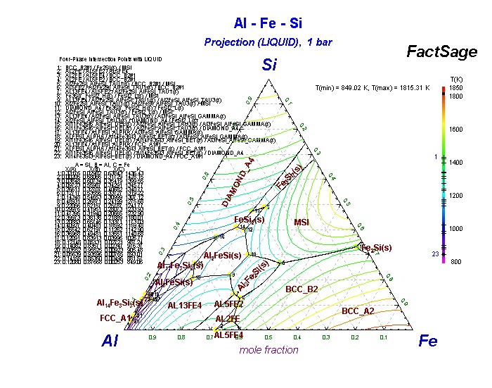
THERMODYNAMIC MODELING OF PHASE COMPOSITION FOR Fe-Ca-Si ... carried out to plot the phase structure diagram of the Fe-Ca-Si-Al system as a modeling composition of the final alloy by the method of thermodynamic diagram analysis (TDA). TDA allows obtaining data for the system in the form of a phase diagram, each elementary subsystem in this diagram is independent. Subsystem can be regarded as a quasi-system. Portion of Fe-Al-Si Phase diagram calculated by Thermo-Calc™. Download scientific diagram | Portion of Fe-Al-Si Phase diagram calculated by Thermo-Calc™. from publication: Study on the Formation of Reaction Phase to Si Addition in Boron Steel Hot-Dipped in ...
Microstructural Characterization and Phase Diagram ... A systematic characterization of a less known Al, Fe, Mn, and Si phase in a SiC particulate-reinforced 2014Al composite (SiC p /2014Al) was performed. In addition to the expected CuAl 2 phase, the Al, Fe, Mn, and Si phase was formed as either an adhesion (>1 µ m) onto SiC in the as-cast composite, or as a precipitate (<100 nm) in the matrix after hot extrusion.

Fe si phase diagram
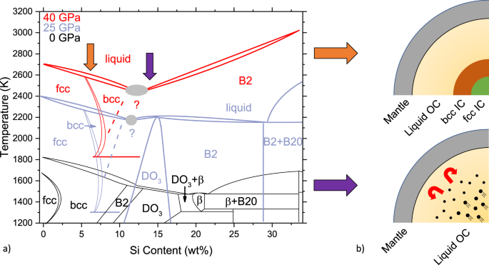
PDF Phase Diagrams of Fe-Si Alloys under High Pressures Phase Diagrams of Fe-Si Alloys under High Pressures J. F. Lin,1 D.L. Heinz,1,2 A. J. Campbell,1 J. M. Devine1 1Department of the Geophysical Sciences and 2James Franck Institute, The University of Chicago, Chicago, IL, U.S.A. Introduction Iron is the most abundant element in the Earth's core. Fe-Si-Ti Ternary Phase Diagram Evaluation - SpringerMaterials Fe-Si-Ti Ternary Phase Diagram Evaluation. Phase diagrams, crystallographic and thermodynamic data. Wei Xiong, Yong Du, Chao Zhang and MSIT® Abstract. PDF The iron-iron carbide (Fe-Fe3C) phase diagram Si Mn W Mo Review Fe-C phase diagram • 2 important points-Eutectoid (B): γ⇒α+Fe 3C-Eutectic (A): L ⇒γ+Fe 3C Fe 3 C (cementite) 1600 1400 1200 1000 800 600 400 0 12 3 4 5 66.7 L γ (austenite) γ+L γ+Fe 3C α+Fe 3C α + γ L+Fe 3C δ (Fe) C o, wt% C 1148°C T(°C) α 727°C = Teutectoid A R S 4.30 Result: Pearlite = alternating layers ...
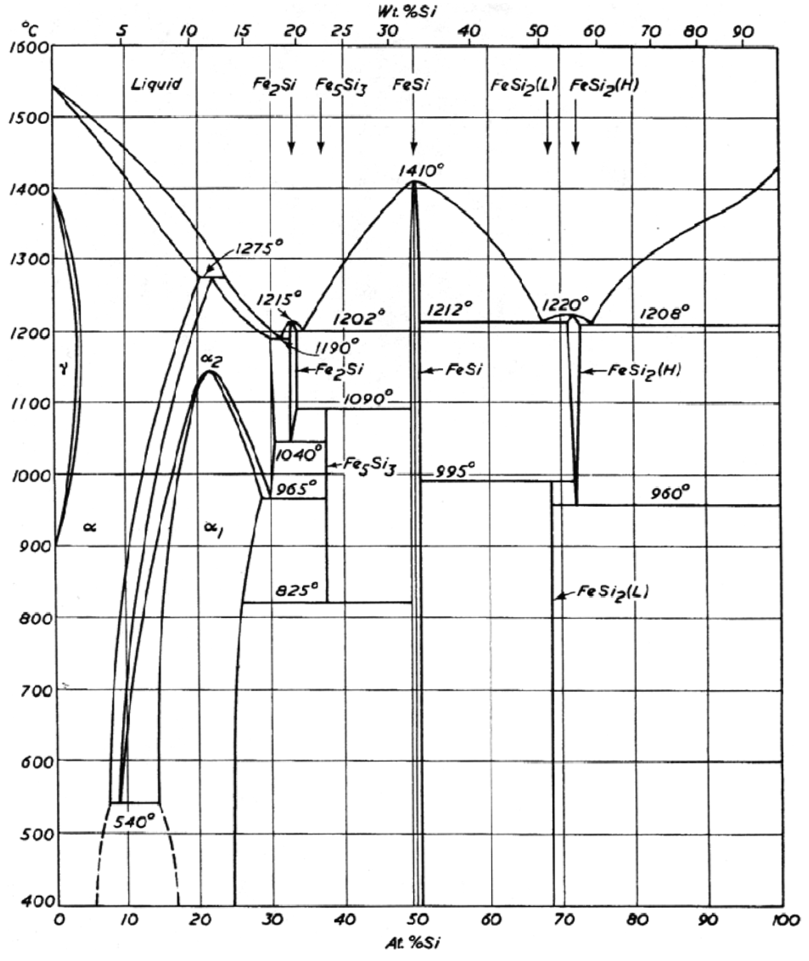
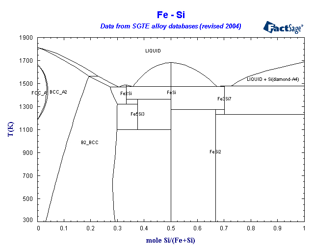
Fe si phase diagram. The Fe-Si phase diagram: from electrical steel to the ... The standard phase diagram for Fe-Si is the one by Kubaschewski (1982). In the iron-rich region, the dominant phases are a-Fe (0 at.%. Si), DO3 (a1, 25 at.%. Si) and B20 (e, 50 at.%. Si). a and a1 have the bcc lattice as underlying lattice, and a1 consists of an ordered replacement of one quarter of the Fe atoms by Si. Ternary Phase Diagrams - ASM International Chapter 10: Ternary Phase Diagrams / 195. Fig. 10.5 . Isopleth through hypothetical ternary phase diagram at a constant . 40% . C. adapted from ref 10.1. SPB Line. The single-phase boundary line is found on any section that . contains a single-phase region. The line is what its name implies. It is the boundary line around that single-phase region. The FeSi phase diagram to 150 GPa - AGU Journals subsolidus phase diagram of FeSi are directly relevant to the CMB region. Second, the high‐pressure phase diagram of FeSi will help to constrain the topology of the Fe‐rich portion of the Fe‐Si system, which is important in deter-mining the distribution of Si within the core and lower mantle at the present day and during core formation Phase diagram and thermal expansion measurements on ... - PNAS Specifically, the substitution of the smaller Fe ions for Ru ions in URu 2 Si 2 appears to act as a chemical pressure such that the temperature vs. Fe concentration (T - x) phase diagram for the URu 2−x Fe x Si 2 system resembles the temperature vs. applied pressure (T - P) phase diagram for URu 2 Si 2.
PDF IRON CARBON PHASE DIAGRAM - Higher Technological Institute transformation in relation to Fe-C diagram ... -Si-substitutes partially for C and promotes ... component instead Fe 3 C. SUMMARY 1). Phase diagrams are useful tools to determine:-the number and types of phases, the wt% of each phase and the composition of each phase for a given T and composition Phase equilibria and structural investigations in the ... The ternary phase reactions in the system Al-Fe-Si were studied by DTA analysis of samples situated in six different vertical sections at 5 at.%. Al and at constant Fe contents of 27, 35, 40, 50 and 60 at.%. Two heating- and cooling-cycles were performed in each measurement. PDF Chapter 2 Alloys of the Al-Mg-Si-Fe System 2.1. Al-Mg-Si PHASE DIAGRAM The Al-Mg-Si phase diagram can be used for the analysis of many wrought alloys of 6XXX series and casting alloys of the 356.0 type, provided the concentration of iron impurity is low (Table 2.1). This diagram is also the basic diagram for casting alloys of the 512.0 type that are considered in Chapter 4. (PDF) Fe-Ni-Si (Iron-Nickel-Silicon) - Academia.edu The phase equilibria were studied with Fig. 1 Fe-Ni-Si isothermal section at 850 °C [2009Zha] 184 Journal of Phase Equilibria and Diffusion Vol. 31 No. 2 2010 Phase Diagram Evaluations: Section II optical and scanning electron metallography, x-ray powder References diffraction, and energy dispersive x-ray analysis/electron probe microanalysis.
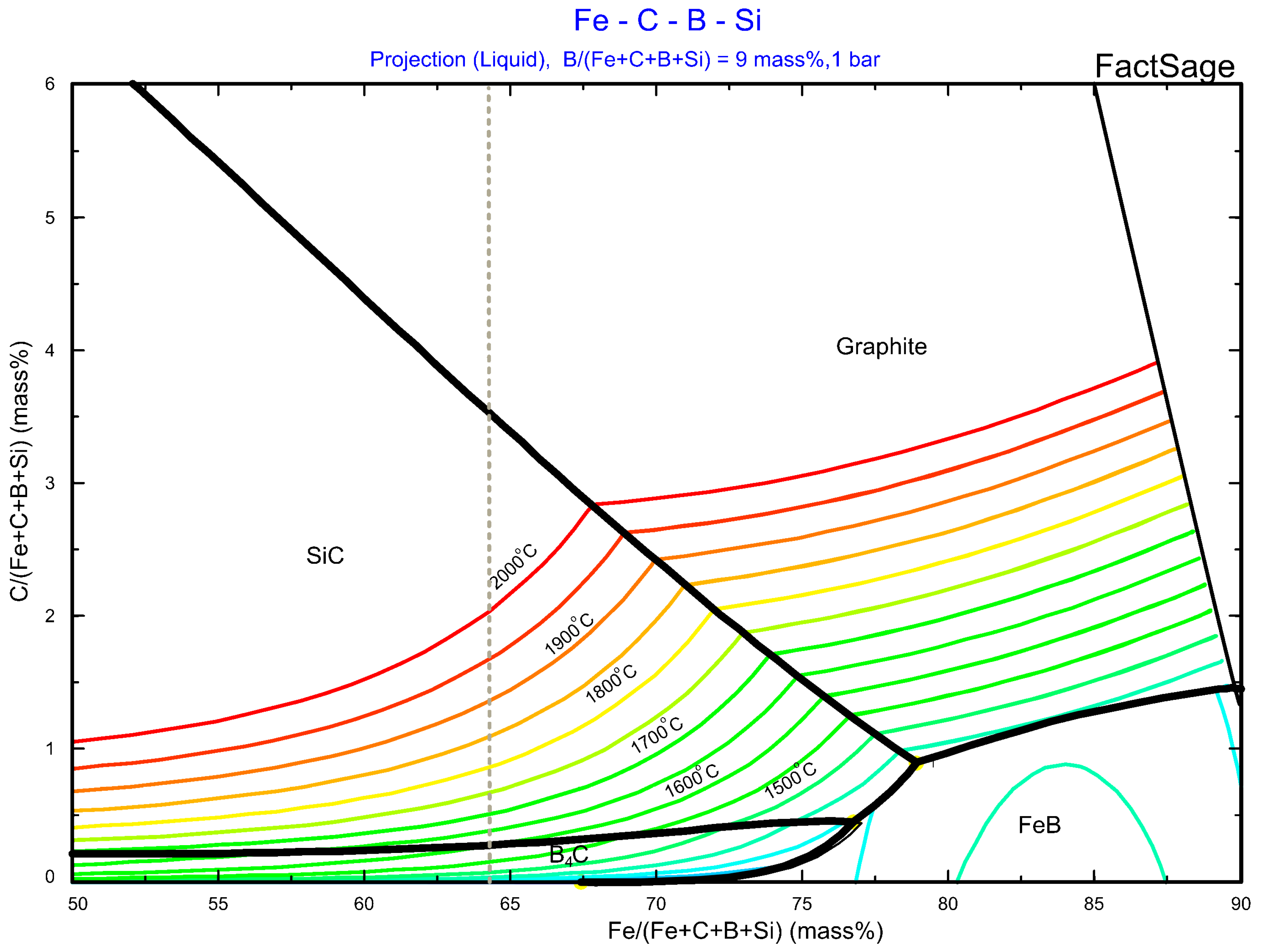
The Fe-FeSi phase diagram at Mercury's core conditions Literature on the Fe-Si system at high pressures report a series of miscibility gaps in the solid phase, between Si-poor hcp or fcc phases and an Si-rich B2 phase 26,28,38, or between the Si ... ON THE EQUILIBRIUM DIAGRAM OF Fe-Ni-Si SYSTEM AND THE ... The sigma -phase was found to be ferromagnetic and formed by a peritectoid reaction alpha + gamma yields sigma , having a maximum temperature at about 920 deg C, at an originai composition of abcut 29% Ni, 11% Si, and 60% Fe, corresponding to the chemical formula Fe/sub 11/Ni/sub 5/Si/sub 4/, after solidifying through an eutectic reaction. Fe-La-Si Ternary Phase Diagram Evaluation - SpringerMaterials Fe-La-Si Ternary Phase Diagram Evaluation. Phase diagrams, crystallographic and thermodynamic data. Gabriele Cacciamani and MSIT® Abstract. This report for the ternary system Fe-La-Si discusses binary systems, solid phases, isothermal sections, thermodynamics, and materials properties and applications. DIAGRAM OF EQUILIBRIUM PHASE COMPOSITION OF Fe - C - Si ... 307 A. ISAGULOV et al.: DIAGRAM OF EQUILIBRIUM PHASE COMPOSITION OF FE - C - SI - B SYSTEM METALURGIJA 55 (2016) 3, 305-308 It permitted to establish in the Fe - C - Si - B system 7
Phase constitution and microstructure of the Fe–Si–Cr ternary ...
Intermetallic compound formation in Fe-Al-Si ternary ... The composition of the τ 5 phase can be approximately represented by the formulae Fe 2 Al 7 Si, which is close to the (Fe 17 Al 72 Si 11) phase reported by Murav'eva et al. . The K 5 phase of Takeda and Mutuzaki [1] , which is supposed to be the same phase as τ 5 , is reported to have a different composition, Fe 6 Al 15 Si 5 .
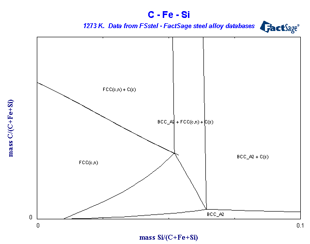
FSstel - FactSage Steel Alloy Phase Diagrams
PDF The Al-Si Phase Diagram - Buehler The Al-Si Phase Diagram The binary Al-Si phase diagram was initially studied by Fraenkel of Germany in 1908. It is a relatively simple binary diagram where there is very little solubility at room temperature for Si in Al and for Al in Si. Thus, the terminal solid solutions are nearly pure Al and Si under equilibrium conditions.

Characterization of the evaluation of the solid solubility of ...
Phase diagram (a) Fe-Si and (b) Mn-Si, and the Si content ... Fe-Si phase diagram ( Fig. 2(a)) there are two eutectic points: (1) at 1 195°C and 19 wt% Si and (2) at 1 202°C and 21.5 wt% Si; there are also two eutectic points for the Mn-Si phase diagram ...
Al-rich Fe-Al based alloys : phase equilibria ...
Thermo-Calc of the Phase Diagram of the Fe-Si System ... Abstract. In this work Thermo-Calc software was used to calculate the phase diagram of the Fe-Si system. The deduced phase diagram includes twenty fields, where three fields represent pure phases; two solid solutions and a liquid phase. There are several fields of two co-existing phases; mixed solid phases, and mixed solid with liquid phases.

PDF) Fe-Ni-Si (Iron-Nickel-Silicon) | Vijayaraghavan ...
Phase diagram of Fe-Cu-Si ternary system above 1523 K ... Fe-Cu-Si ternary alloy phases are commonly formed during melting in a treatment process of domestic waste incineration that is currently being developed. The alloy phases appear in the incineration residue. Experiments were performed to observe phase equilibria in solid Fe+liquid, solid Si+liquid, the compound of FeSi liquid, and so forth, in the range 1523 to 1723 K. Then the phase diagram of ...

The FeSi phase diagram to 150 GPa - Lord - 2010 - Journal of ...
SGTE Alloy Phase Diagrams - FactSage.cn SGTE Alloy Phase Diagrams. Click on a system to display the phase diagram.

Evidence for Fe-Si-O liquid immiscibility at deep Earth ...
PDF PHASE RELATIONS OF Mn-Fe-Si-CSYSTEMS PHASE RELATIONS OF Mn-Fe-Si-CSYSTEMS Eivind G. Hoel Elkem Mangan KS Sauda, Norway ABSTRACT Phase relations ofMn-Fe-Si-Csystems are established by means ofreported binary diagrams, and calculations of ternary and quaternary diagrams. The phase relations are presented in diagrams for six binary and four higher order
Formation of intermetallic phases in Al-10Si-0.3Fe based alloys
Phase Diagram - Google Search 計算熱力学はいわば"物性推算法"の一つであり、用いる熱力学データベースも、もっとも良さそうな"推算値"で構成されています。. これらは様々な情報に基づき、細心の注意を払って推定されたものですが、間違いや問題はあり得ます。. 従って、それ ...

Si-Fe - Phase Diagram
PDF Chapter 1 Alloys of the Al-Fe-Mn-Si System 1.1. Al-Fe-Si PHASE DIAGRAM The Al-Fe-Si system is the basic system for the structure analysis of commercial aluminum alloys of the 8111 type, and binary Al-Si alloys which, as a rule, contain an iron impurity (Table 1.1). The aluminum corner of the Al-Fe-Si phase diagram is considered in detail by
Solidification of steels
All Phase Diagrams - Polytechnique Montréal FactSage 8.1 - List of Stored Phase Diagrams (7811) FACT Databases. FToxid FACT oxide data (501) FTsalt salt data (351) FTmisc sulfide, alloy, micellaneous data (39) ... Ag-Fe-Si_1550C SGnobl: Ag-Ga FScopp: Ag-Ga FSlead: Ag-Ga FTlite: Ag-Ga SGTE 2020: Ag-Gd SGTE 2020: Ag-Ge BINS: Ag-Ge FScopp: Ag-Ge FTlite: Ag-Ge SGnobl: Ag-Ge SGTE 2014: Ag-Ge ...
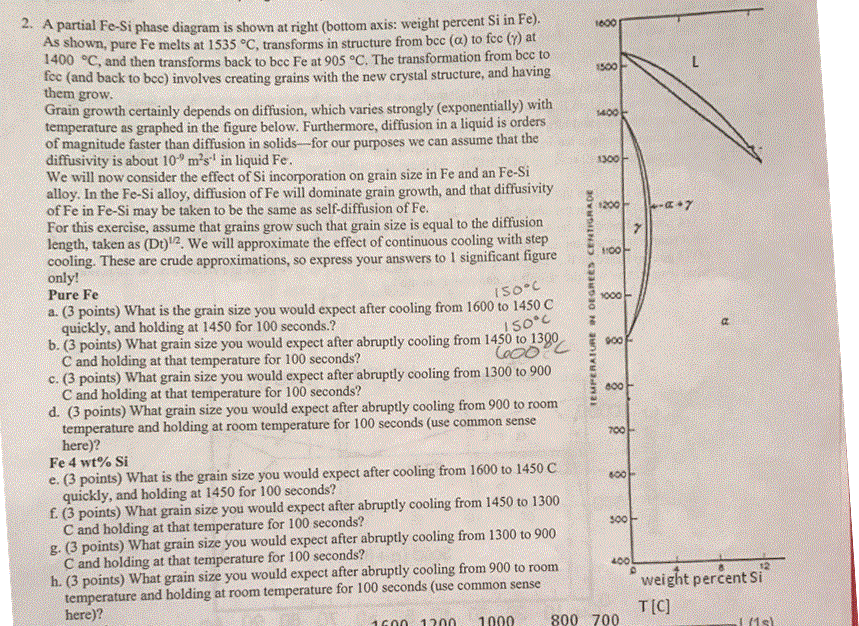
2. A partial Fe-si phase diagram is shown at right | Chegg.com
Computer calculations of metastable and stable Fe-C-Si ... Computer calculations of metastable and stable Fe-C-Si phase diagrams from binary thermodynamic properties Computer calculations of metastable and stable Fe-C-Si phase diagrams from binary thermodynamic properties. Download File. r_8627100.pdf (1004.34 KB) Date. 1986. Authors. Chueh, Shan-Chang. Journal Title. Journal ISSN.

Austenitic Steels :: Total Materia Article
PDF The iron-iron carbide (Fe-Fe3C) phase diagram Si Mn W Mo Review Fe-C phase diagram • 2 important points-Eutectoid (B): γ⇒α+Fe 3C-Eutectic (A): L ⇒γ+Fe 3C Fe 3 C (cementite) 1600 1400 1200 1000 800 600 400 0 12 3 4 5 66.7 L γ (austenite) γ+L γ+Fe 3C α+Fe 3C α + γ L+Fe 3C δ (Fe) C o, wt% C 1148°C T(°C) α 727°C = Teutectoid A R S 4.30 Result: Pearlite = alternating layers ...
![Fe-Si Phase Diagram [16] and alloy quench temperatures ...](https://www.researchgate.net/profile/Shaghayegh-sherry-Esfahani/publication/257786929/figure/fig1/AS:328356257124352@1455297640212/Fe-Si-Phase-Diagram-16-and-alloy-quench-temperatures.png)
Fe-Si Phase Diagram [16] and alloy quench temperatures ...
Fe-Si-Ti Ternary Phase Diagram Evaluation - SpringerMaterials Fe-Si-Ti Ternary Phase Diagram Evaluation. Phase diagrams, crystallographic and thermodynamic data. Wei Xiong, Yong Du, Chao Zhang and MSIT® Abstract.

The ternary Fe–Sb–Si system: Experimental phase diagram study ...
PDF Phase Diagrams of Fe-Si Alloys under High Pressures Phase Diagrams of Fe-Si Alloys under High Pressures J. F. Lin,1 D.L. Heinz,1,2 A. J. Campbell,1 J. M. Devine1 1Department of the Geophysical Sciences and 2James Franck Institute, The University of Chicago, Chicago, IL, U.S.A. Introduction Iron is the most abundant element in the Earth's core.
Thermodynamic description of the Al–Fe–Mg–Mn–Si system and ...
Exercises on Ch.10 Projected and mixed phase diagrams
Thermodynamic assessment of the aluminum corner of the Al-Fe ...
Fe (Iron) Binary Alloy Phase Diagrams
Alloys of the Al-Mg-Si-Fe System
Collection of Phase Diagrams
Thermodynamic and kinetic analysis of the melt spinning ...
Materials | Free Full-Text | Organometallic Routes into the ...

Free PDF Download - Fe-Si-Zn (Iron-Silicon-Zinc ...
Lightweight High Temperature Alloys based on the AlFeSi ...
Collection of Phase Diagrams

Melting experiments on Fe–Si–S alloys to core pressures ...
Collection of Phase Diagrams
Teach Yourself Phase Diagrams and Phase Transformations
The equilibrium Fe-Si phase diagram showing the B2 BCC phase ...
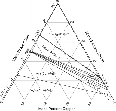
Cu-Fe-Si (Copper-Iron-Silicon) | SpringerLink

Characterization of the Fe-rich corner of Al-Fe-Si-Ti ...
The Fe-FeSi phase diagram at Mercury's core conditions ...
![Iron-Carbon Phase Diagram Explained [with Graphs]](https://fractory.com/wp-content/uploads/2020/03/Iron-carbon-phase-diagram-explained.jpg)
Iron-Carbon Phase Diagram Explained [with Graphs]

The Iron Carbon Phase Diagram
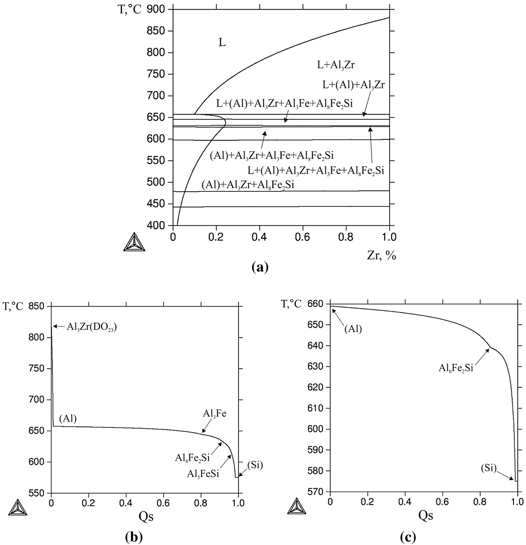
Figure 1 | Structure and Properties of Al-0.6%Zr-0.4%Fe-0.4 ...
Materials | Free Full-Text | The Use of Eutectic Fe-Si-B ...

File:Fe-P-phase-diagram-greek.svg - Wikimedia Commons
The dependence of the ß-AlFeSi to α-Al(FeMn)Si transformation ...
Example E1: Stable and meta-stable phase diagram of Fe-C-Mn ...
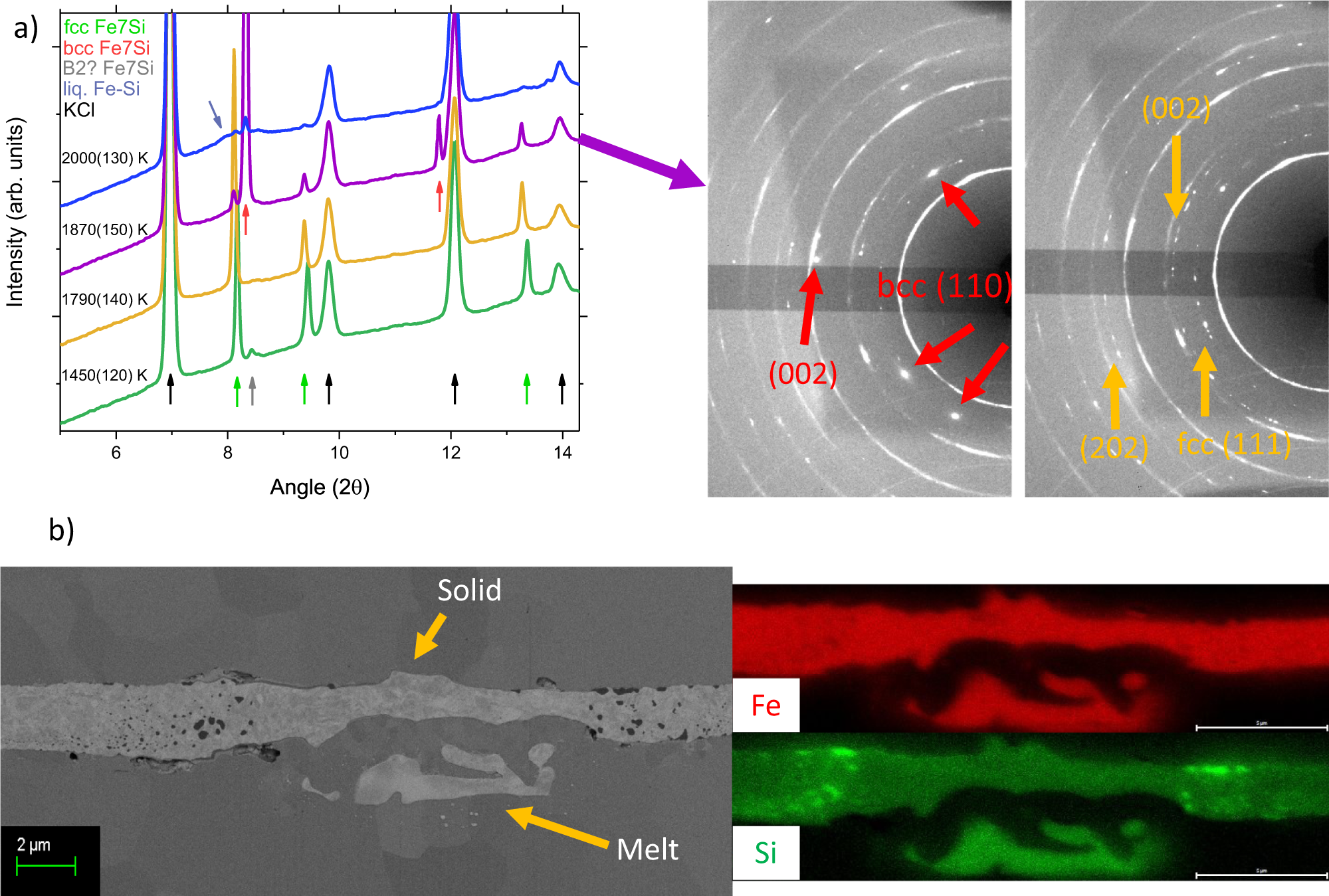
The Fe-FeSi phase diagram at Mercury's core conditions ...
Casts Irons The cast irons are made and used by many ...
0 Response to "41 fe si phase diagram"
Post a Comment