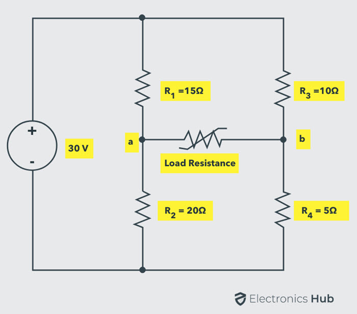
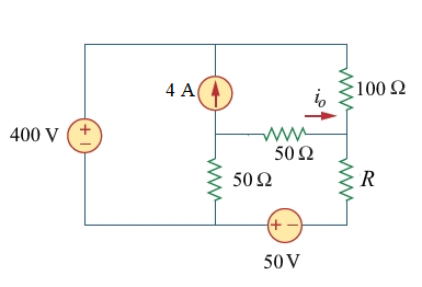
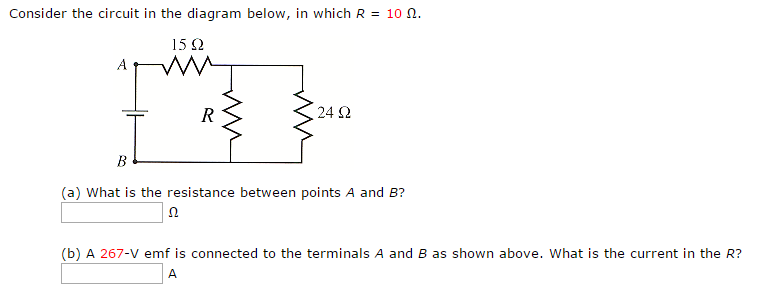
42 consider the circuit in the diagram below, in which r = 10 ω.
[Solved] Consider the network shown below with 𝑅1 = 1 Ω, Download Solution PDF. Consider the network shown below with 𝑅 1 = 1 Ω, 𝑅 2 = 2 Ω and 𝑅 3 = 3 Ω. The network is connected to a constant voltage source of 11 V. The magnitude of the current (in amperes, accurate to two decimal places) through the source is ________. This question was previously asked in. Deduce the expression for the equivalent ... - Sarthaks Consider the following parallel circuit shown below: Let I 1, I 2 and I 3 be the current flow through the resistor R 1, R 2 and R 3 connected in parallel. Using Ohm's law, current through each resistor is. I 1 = V/R 1, I 2 = V/R 2 and I 3 = V/R 3. Let their equivalent resistance be R p then. V = I R p ⇒ I = V/R p. Total current through the circuit is
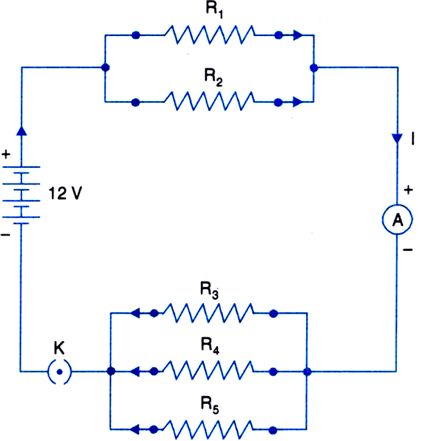
Consider the following circuit diagram. If R1 = R2 = R3 ... Consider the following circuit diagram. If R 1 = R 2 = R 3 = R 4 = R 5 = 3 Ω the equivalent resistance of the circuit is. A. 9 ...
Consider the circuit in the diagram below, in which r = 10 ω.
Problem 1: 25 points Use the following circuit diagram to ... Problem 2: 25 points Consider the RC circuit shown below, with R 1 = 5 Ω, R 2 = 5 Ω, R 3 = 10 Ω, and C 1 = 10 μ F. The switch S 1 has been open for a very long time, and the capacitor C 1 initially is uncharged. (a) What is the time constant of this circuit? (b) You would like to modify this circuit to have a time constant of 150 μ s. Consider the circuit in the diagram below. in which r = 11 ω. 3 Jan 2022 — The resistance R and 24 ohms are in paralle so using the parallel equivalent of resistance we get (11*24)/(11+24) ohms accross end of 15 ohms ... In the circuit diagram given below five resistances of 10 ... In the circuit diagram given below five resistances of 10 Ω, 40 Ω, 30 Ω, 20 Ω and 60 Ω are connected as shown to a 12 V battery. Calculate : (a) total resistance in the circuit. (b) total current flowing in the circuit.
Consider the circuit in the diagram below, in which r = 10 ω.. Question with solution (circuit diagram) - My Electrical Note Therefore they can be simplified as (10 * 10)/(10 + 10) = 5 Ω The simplified circuit diagram can be drawn as: I = V/R 8 = (100/(R + 5)) 8R + 40 = 100 8R = 100 - 40 8R = 60 R = 7.5 Ω. Question 5: Find the value of resistance R from the circuit diagram given below? Solution: Applying KCL . From the figure given above we can know that: I = I1 + 4 Consider the circuit shown (in the link below), determine ... Consider the circuit shown (in the link below), determine the time required for the capacitor to reach a full charge ... (10*10^3 Ω)(0.0001f) T= 1s ... 24μF is connected in series with a 90-V battery. (i) Draw an open circuit diagram for this arrangement. (ii) Calculate the effective capacitancee in the circuit. Physics. A 3.00 uF and a 5.00 ... PDF XII. AC Circuits - Worked Examples Example 5: RLC Circuit Consider the circuit shown below, assuming that R, L, V0 and ω are known. If both switches are closed initially, find the following: (a) the current as a function of time, (b) the average power delivered to the circuit, (c) the current as a function of time after only switch 1 is opened. [Solved] Find the resistance between terminals A and B in ... Application: The given circuit is modified as shown below: where R 1, R 2, and R 3 are calculated using Wye-Delta transformation as: R 1 = 50 × 40 50 + 40 + 10 = 20 Ω. R 2 = 10 × 50 50 + 40 + 10 = 5 Ω. R 3 = 10 × 40 50 + 40 + 10 = 4 Ω.
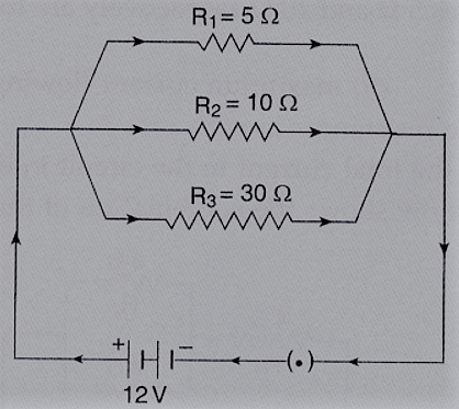
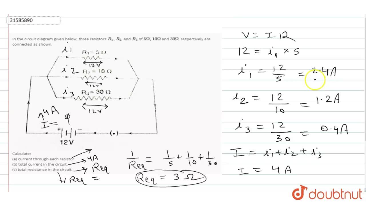
PDF Frequency response of circuit R L ω ω ω == + c R L ω= A Serial RL Circuit Result ECE 307-4 22 Frequency Response of a Circuit Example Define R and L values for a high pass filter with a cutoff frequency of 10KHz. Find |H(jω)|at 5 KHz Let We can't calculate R and L values independently. We can select R or L values then define the other RK=Ω1 c R L ω = 1000 15.9 2 ... PDF A circuit is constructed with five resistors and a battery ... A circuit is constructed with five resistors and a battery as shown. The values for the resistors are: R 1 = R 5 = 77 Ω, R 2 = 90 Ω, R 3 = 83 Ω, and R 4 = 88 Ω. The battery voltage is V = 12 V. 1) What is R ab, the equivalent resistance between points a and b? You try making an awesome looking circuit diagram in Paint! In the circuit diagram given in fig. 12.10, suppose the ... In the circuit diagram given in fig. 12.10, suppose the resistors R 1 , R 2 and R 3 have the values 5 Ω, 1 0 Ω, 3 0 Ω respectively, which have been connected to a battery of 12V. calculate (a) the current through each resistor, (b) the total current in the circuit, and (c) the total circuit resistance. Solved Consider the circuit shown in the diagram below ... Consider the circuit shown in the diagram below. The battery has a voltage V = 12.0 V and the resistors have the following values. R1 = 2.32 2; R2 = 4.64 2, R2 = 11.60 2; R = 6.96 2 How much current flows through each of the four resistors? w RA ; Question: Consider the circuit shown in the diagram below. The battery has a voltage V = 12.0 V ...
consider the following circuit diagram if r1 r2 r3 r4 r5 ... Contact us on below numbers. For Study plan details. 1800-212-7858 / 9372462318. ... Consider the following circuit diagram. If R 1 = R 2 = R 3 = R 4 = R 5 = 3Ω, ... Judge the equivalent resistance when the following are connected in parallel - (a) 1 Ω and 106Ω, (b) 1Ω and 103Ω and 106Ω. can you please answer this question fast. ... VC R VA Ω Both the current passing through and the ... 5. 10/10 points | Previous Answers Consider the water circuit shown in the diagram below, where water is pumped through a series of pipes connected in a loop. Assume the pipes are completely filled with water, so that there are no air pockets. Is the amount of water passing point A greater than, less than or equal to the amount of water passing point B? 6. Solved Consider the electric circuit in the figure below ... Consider the electric circuit in the figure below with the following parameters: ε 1 = 24.00 V, ε 2 = 12.00 V, R 1 = 900 Ω, R 3 = 400 Ω.. 1.)What is the potential at point A? 2.)Calculate the current i 1.. 3.)Calculate the current i 3 Physics _ Chap 13 Flashcards - Quizlet The total resistance of the circuit is R=Rbt+Rbulb=3.5 Ω + 19 Ω R=22.5 Ω The current through the 19-Ω resistor is I=VR=6 V22.5 Ω I=0.2667 A The voltage difference ΔVbulb across the 19-Ω resistor is calculated as follows: ΔV=5.0667 V
Example 12.9 - If in Fig. 12.12, R1 = 10, R2 = 40, R3 = 30 ... If in Fig. 12.12, R 1 = 10 Ω, R 2 = 40 Ω, R 3 = 30 Ω, R 4 = 20 Ω, R 5 = 60 Ω, and a 12 V battery is connected to the arrangement. Calculate (a) the total resistance in the circuit, and (b) the total current flowing in the circuit.
Resistors in Circuits - Problems - The Physics Hypertextbook The diagram below shows a circuit with one battery and 10 resistors; 5 on the left and 5 on the right. Determine… the current through; the voltage drop across; the power dissipated by each resistor; Given the circuit below… Calculate the equivalent resistance of the circuit. Calculate the current through the battery.
Lock - in Amplifier and Applications - Lehigh University Let's consider an example. Suppose the signal is a 10 nV sine wave at 10 kHz. Clearly some amplification is required to bring the signal above the noise. A good low noise amplifier will have about 5 nV/ √Hz of input noise. If the amplifier bandwidth is 100 kHz and the gain is 1000, then we can expect our output to be 10μV of signal (10 nV x ...
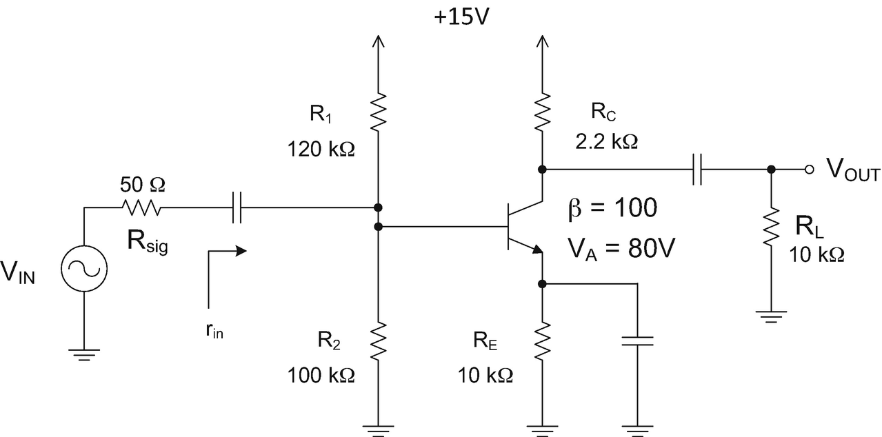
Common Emitter Amplifier - Electronics-Lab.com A resistance R L is in parallel with the resistance R C of the collector, it represents a load, that is to say the next stage of the circuit after the CEA : it can be an antenna, a speaker or simply another amplifier or stage of the electronic circuit. The resistance R S represents the internal resistance of the sine source.
Example 12.8 - In the circuit diagram given in Fig. 12.10 ... In the circuit diagram given in Fig. 12.10, suppose the resistors R 1 , R 2 and R 3 have the values 5 Ω, 10 Ω, 30 Ω, respectively, which have been connected to a battery of 12 V. Calculate (a) the current through each resistor, (b) the total current in the circuit, and (c) the total circuit resistance.
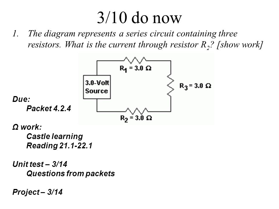
3/6 do now A piece of copper wire with a cross-sectional area of 3.0 x 10⁻⁵ meter2 is 25 meters long. How would changing the length of this copper wire.
PDF PHYS-2020: General Physics II Course Lecture Notes Section IV Example IV-1. Consider the circuit shown below, where R1 = 3.00 Ω, R2 = 10.0 Ω, R3 = 5.00 Ω, R4 = 4.00 Ω, and R5 = 3.00 Ω. (a) Find the equivalent resistance of this circuit. (b) If the total power supplied to the circuit is 4.00 W, find the emf of the battery. + − E R1 R2 R3 R4 R5 Solution (a): We have to reduce this circuit in steps ...
Answered: Consider the circuit in the diagram,… | bartleby Consider the circuit in the diagram, with sources of emf listed below. Randomized Variables E = 22 V Ez = 44 V E3 = 3.5 V 0.10 2 R 5.0 Ω E2 202 E4 = 45 V R a 0.50 2 40 2 0.20 요 R 78 2 E3 i 0.05 2 h A. Find Ij in amps. B. Find I2 in amps. C. Find I3 in amps.
PDF theonlinephysicstutor The diagram below shows the circuit for a small convector heater. Heater elements can be switched in and out of the circuit using switches X and Y. Each element has a resistance R and the power supply has an emf V. (a) The table shows the possible combinations of open and closed switches. When a switch is closed, charge can flow through it. 17
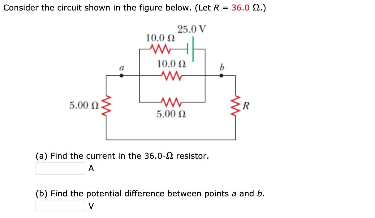
Consider the circuit shown in the figure b... | Clutch Prep Problem Details. Consider the circuit shown in the figure below. (Let R = 36.0 Ω.) (a) Find the current in the 36.0-Ω resistor. A. (b) Find the potential difference between points a and b. V. Learn this topic by watching Solving Resistor Circuits Concept Videos.
consider the circuit shown in the diagram find the current ... consider the circuit shown in the diagram find the current in 3 Ω resistor - Physics - TopperLearning.com | ij7jct7kk. consider the circuit shown in the diagram find the current in 3 Ω resistor - Physics - TopperLearning.com | ij7jct7kk ... Need assistance? Contact us on below numbers. For Study plan details. 1800-212-7858 / 9372462318. 10:00 ...
PDF Chapter 21: RLC Circuits - Department of Physics PHY2054: Chapter 21 2 Voltage and Current in RLC Circuits ÎAC emf source: "driving frequency" f ÎIf circuit contains only R + emf source, current is simple ÎIf L and/or C present, current is notin phase with emf ÎZ, φshown later sin()m iI t I mm Z ε =−=ωφ ε=εω m sin t ω=2πf sin current amplitude() m iI tI mm R R ε ε == =ω
Finding current through resistor ... - Physics Forums Homework Statement Consider the circuit shown in the diagram below, for R1 = 5 Ω, R2 = 8 Ω, R3 = 8 Ω, R4 = 8 Ω, and V0 = 8.0 V. Calculate the current through R4. Homework Equations Loop rule: The sum of all potential changes around a closed loop is zero Junction rule...
Answered: In the diagram below, R1=30 Ω, R2=13 ... - bartleby In the diagram below, R 1 =30 Ω, R 2 =13 Ω, R 3 =40 Ω, and R 4 =30 Ω. At first, a segment with R 4 is disconnected from the circuit and then it is connected as shown. Find the equivalent resistance before the R 4 is attached: R eq i = Ω. Find the current passing through the R 3 resistor before the R 4 is attached: I i = A. Find the equivalent resistance after the R 4 is attached:
Consider the diagram below. Find the current (magnitude ... Consider the diagram below. Find the current (magnitude and direction) in the 10.0 ohm resistor. 20.0 Ω 5.0 Ω 10.0 Ω +10.0 V 10.0 V 20.0 V Find the magnitude and direction of the current through resistor R in the circuit shown if... Find the magnitude and direction of the current through resistor R in the circuit shown if R=57 ΩΩ and V=13 V.
In the circuit diagram given below five resistances of 10 ... In the circuit diagram given below five resistances of 10 Ω, 40 Ω, 30 Ω, 20 Ω and 60 Ω are connected as shown to a 12 V battery. Calculate : (a) total resistance in the circuit. (b) total current flowing in the circuit.
Consider the circuit in the diagram below. in which r = 11 ω. 3 Jan 2022 — The resistance R and 24 ohms are in paralle so using the parallel equivalent of resistance we get (11*24)/(11+24) ohms accross end of 15 ohms ...
Problem 1: 25 points Use the following circuit diagram to ... Problem 2: 25 points Consider the RC circuit shown below, with R 1 = 5 Ω, R 2 = 5 Ω, R 3 = 10 Ω, and C 1 = 10 μ F. The switch S 1 has been open for a very long time, and the capacitor C 1 initially is uncharged. (a) What is the time constant of this circuit? (b) You would like to modify this circuit to have a time constant of 150 μ s.














0 Response to "42 consider the circuit in the diagram below, in which r = 10 ω."
Post a Comment