40 mercruiser thunderbolt iv ignition module wiring diagram
Thunderbolt Iv Mercruiser Thunderbolt Ignition Wiring ... Thunderbolt Iv Mercruiser Thunderbolt Ignition Wiring Diagram : Replacement Kits For Thunderbolt Iv Ignition Control Module Perfprotech Com - This is a hash browns and cheese casserole that is easy to prepare, serve and is loved by everyone! - Stella Stretton Mercruiser Thunderbolt Iv Ignition Wiring Diagram - Irish ... Mercruiser Thunderbolt Iv Ignition Wiring Diagram. Mercruiser Thunderbolt Iv Ignition Wiring Diagram. Irish Connections ... Replacement kits for thunderbolt iv ignition control module perfprotech com need wiring schematic v 1996 merc i o 4 3 gm v6 how mercruiser systems work boating forum iboats forums info needed on to hook up a msd offsonly ...
Thunderbolt 4 Ignition Wiring Diagram - Wiring diagram online Wiring Diagram Mercruiser Thunderbolt Iv Ignition 4.3 V6 from schematron.org. Mercruiser thunderbolt ignition manual download. From sm #17, t4 alpha module on exhaust elbow: Inspect the ignition key wiring for a loose or broken wire strands on the.
Mercruiser thunderbolt iv ignition module wiring diagram
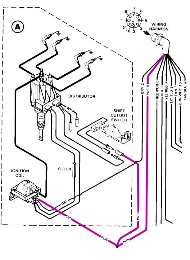
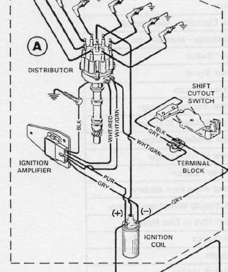
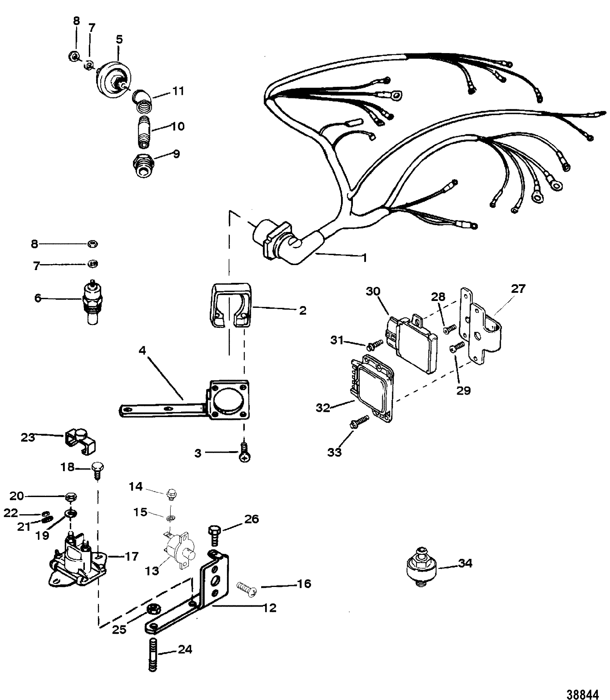
TESTING THUNDERBOLT IV HEI IGNITION SYSTEM - Frequently ... How do I troubleshoot my Thunderbolt Ignition? Use a voltmeter when making these tests. Do not use a test light. Source: Mercury Marine Service Bulletin 92-11. Mercruiser Thunderbolt Iv Ignition Module Wiring Diagram ... Ignition sensor kit mercruiser thunderbolt i iv distributor. So from what i've read about the thunderbolt iv ignition . If there is spark, replace the ignition sensor in the dist. Find many great new & used options and get the best deals for w4 mercruiser thunderbolt iv module harness ignition v6 at the best online prices at ebay! Thunderbolt IV wiring diagram - Offshoreonly.com Thunderbolt IV mounted on exhaust elbow wht/red from module to dis. wht/grn from module to dis. gray neg on coil to tac. and to module. purple on pos. coil from module and kill switch /ignition. blk. is ground .
Mercruiser thunderbolt iv ignition module wiring diagram. Mercruiser Thunderbolt Iv Ignition Module Wiring Diagram ... Mercruiser Thunderbolt Iv Ignition Module Wiring Diagram. Replacement kits for thunderbolt iv ignition control module perfprotech com distributor components 1988 inboard engine 5 7l ski 3570111as crowley marine how mercruiser systems work boating forum iboats forums info needed on to hook up a msd offsonly wiring harness electrical ign 1992 7 ... Mercruiser Wiring Diagram - Wirings Diagram Mercruiser Wiring Diagram - mercruiser 140 wiring diagram, mercruiser alternator wiring diagram, mercruiser ignition wiring diagram, Every electric structure consists of various distinct parts. Each component ought to be placed and connected with different parts in particular way. If not, the arrangement will not work as it should be. Mercruiser Ignition Wiring Diagram - Wiring Sample Mercruiser Ignition Wiring Diagram. The TB-IV system was used until the introduction of TB-V mid-way through 1996. According to previous the traces in a Mercruiser Wiring Diagram signifies wires. At times the cables will cross. Injunction of two wires is generally indicated by black dot to the intersection of 2 lines. Mercruiser Thunderbolt V Ignition Wiring Diagram 4F-0 - WIRING DIAGRAMS Table of Contents WIRING DIAGRAMS - 4F-1 Wiring Colors for MerCruiser NOTE: Color codes listed below DO NOT apply to fuel injection system harnesses. WIRING DIAGRAMS - 4F-3 THUNDERBOLT IV WITH IGNITION MODULE MOUNTED ON. Thunderbolt v ignition w/o knock sensor.
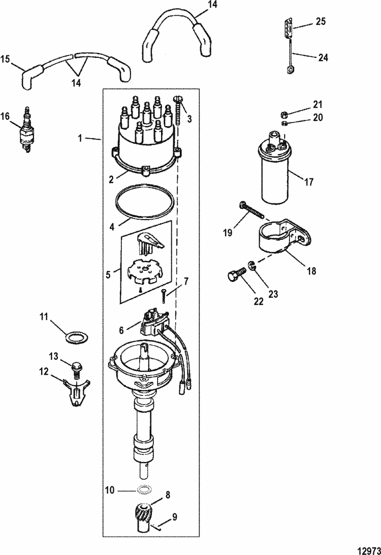
Mercruiser Thunderbolt Wiring Diagram 4. Only Register an Account to DownloadWiring Diagram For A V6 Thunderbolt Iv Ignition. Mercruiser Engine PDF. Online PDF Related to Wiring.Aug 30, · I've tried searching the forums, but only came up with wiring diagrams for older engines. If anyone has a link or pic of the engine wiring diagram for a 91 Mercruiser w/the Thunderbolt ignition ... Mercruiser Thunderbolt Iv Ignition Module Wiring Diagram Mercruiser Thunderbolt Iv Ignition Module Wiring Diagram 16.11.2018 2 Comments Thunderbolt IV mounted on exhaust elbow wht/red from module to dis. to module. purple on pos. coil from module and kill switch /ignition. blk. Thunderbolt IV is a battery powered High Energy Ignition system, not a CD system. PDF Electrical Systems 90-806535950 694 IGNITION SYSTEM - 4B-3 Thunderbolt IV (HEI) Ignition System 72722 a - Ignition Module a Special Tools Mercury Marine Special Tools Description Part Number Timing Light 91-99379 Multi Meter/DVA 91-99750 Torch Lamp 91-63209 Insulating Compound 92-41669 Quicksilver Liquid Neoprene 92-25711 Torque Specifications Description lb. in ... Mercruiser Thunderbolt Ignition Wiring Diagram - Letterlazb Mercruiser Thunderbolt Ignition Wiring Diagram.The sensor (a device that acts like a switch when subjected to. Thunderbolt v ignition wiring diagram harness electrical components mercury iv i have a 1993 stingray with 4 3 how mercruiser liter cp performance systems diagrams source control module system manualzz also 470 boat supposed to an 5 7l efi gm 350 8 1998 1978 outboard and simularities ...
Thunderbolt IV wiring question | Boating Forum - iboats ... Re: Thunderbolt IV wiring question. From SM #17, T4 Alpha Module on exhaust elbow: Purple: Coil +. Gray: Coil -. The blacks are ground. The wht/red and wht/grn go from dist to module. The wht/grn also goes from dist terminal to gray at shift interupt. You need a T4/5 coil. T4 doesn't use a resistive wire. MerCruiser 7.4L Bravo (Gen. V) GM 454 V-8 1992-1996 Wiring ... MerCruiser 7.4l bravo (gen. v) gm 454 v-8 1992-1996 wiring harness/electrical(thunderbolt v ignition) parts. Buy a genuine Mercury Quicksilver or aftermarket part. Mercruiser Ignition Module Test [Z1X4D2] Search: Mercruiser Ignition Module Test. About Mercruiser Module Ignition Test Mercruiser 4.3 Wiring Diagram - Wiring Diagram Mercruiser Ignition Coil Wiring Diagram - Today Wiring Diagram - Mercruiser 4.3 Wiring Diagram. Wiring Diagram will come with a number of easy to stick to Wiring Diagram Directions. It is meant to assist all of the typical consumer in building a correct method. These directions will probably be easy to grasp and use.
Replacement Kits for Thunderbolt IV Ignition Control Module ...
PDF Service Manual Number 25 Thunderbolt V Ignition System ... SERVICE MANUAL NUMBER 25 THUNDERBOLT V IGNITION SYSTEM 90-861328--1 NOVEMBER 1999 Page 4B-1 ELECTRICAL SYSTEMS ... ignition and fuel system components on your MerCruiser power package ... jumper wire is left in place, the ignition module will operate in the Base Timing Mode.
MERCRUISER® IGNITION
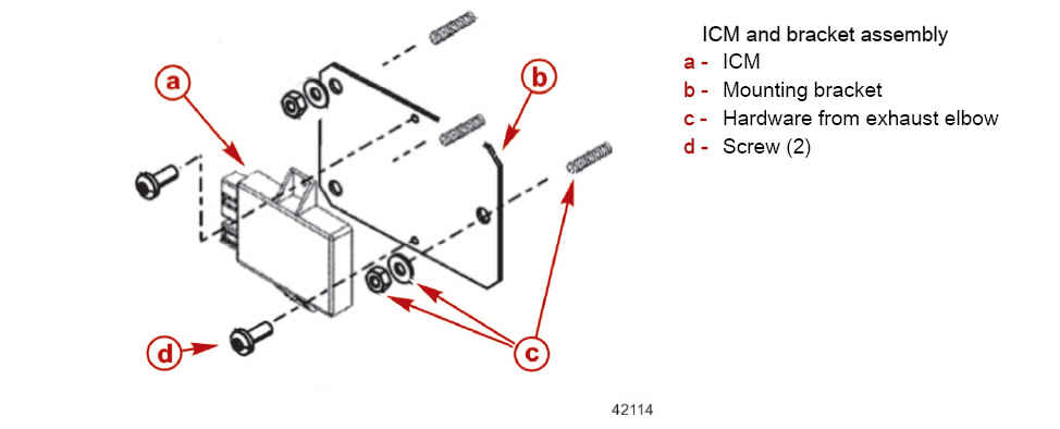
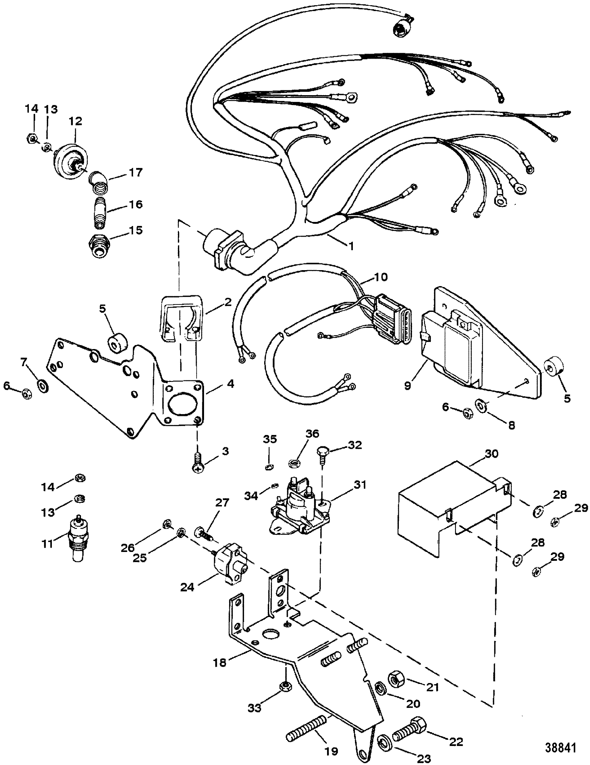
PDF No Ignition Mercruiser 350 MPI 16B4R2 Boat Stuff Thunderbolt IV Ignition Module IGNITION MODULE MOUNTED ON EXHAUST ELBOW 1. Unplug wiring harness connector from ignition module. 2. Remove fasteners and hardware retaining igni-tion module to exhaust elbow. Remove module. NOTE: Do not disturb spacers between ignition mod-ule plate and exhaust elbow, unless replacing spacers.

805759Q3 Distributor Cap Kit for Marinized V-8 GM Engines with Thunderbolt IV & V HEI Ignition Systems
Wiring Diagram Mercruiser Thunderbolt Iv Ignition 4.3 V6 Wiring Diagram Mercruiser Thunderbolt Iv Ignition 4.3 V6. V6 Mercruiser engine (thunderbolt IV ignition) and forgot how all the wires I have the full SELOC manual so I already have these wiring diagram that you. Fits GM V-6 engines with Thunderbolt IV & V HEI ignition. See application Fits and newer MCM/MIE L, L, L & L MPI engines with ECM Fits ...

Distributor Cap Rotor for MerCruiser 4.3L V6 Thunderbolt IV V ...
Mercruiser Thunderbolt Iv Ignition Wiring Diagram - IOT ... Replacement kits for thunderbolt iv ignition control module perfprotech com how mercruiser systems work boating forum iboats forums info needed on to hook up a msd offsonly distributor components 1988 mercury inboard engine 5 7l ski 3570111as crowley marine no power coil v system manualzz delco wiring harness electrical ign v6 v8 4 3 0 7 454 99… Read More »
Thunderbolt IV Wiring Question - Maxum Boat Owners Club - Forum
39 mercruiser thunderbolt iv ignition wiring diagram ... Mercury Outboard Wiring Diagram s Mastertech Marin. Thunderbolt iv ignition control module 1988 mercury inboard engine 5 7l ski hook up a msd mercruiser systems wiring harness electrical components 94 echelon lx page 9 malibu boats v system manualzz testing hei boat supposed to have an delco parts cp performance replacement and simularities ...
CP Performance - Electrical Components (Ign. Module Mounted ...
Wiring Diagram Mercruiser Thunderbolt Iv Ignition 4.3 V6 Jeff, I have just bought a project 91 Glasstream I/O mercruiser /V6 w/ Thunderbolt IV ignition.4B-8 - IGNITION SYSTEM Thunderbolt IV Ignition Module IGNITION MODULE MOUNTED ON EXHAUST ELBOW 1. Unplug wiring harness connector from ignition module. 2. Remove fasteners and hardware retaining igni-tion module to exhaust elbow. Remove module.

MerCruiser 807829-1 4.3 Alpha Ignition Module Ret for sale ...
Checking Mercruiser Ignition System for GM V-8 Thunderbolt ... This is a complete working ignition system that was removed from a GM V-8 engine with the Thunderbolt 4 ignition system.Here is the youtube location to where...

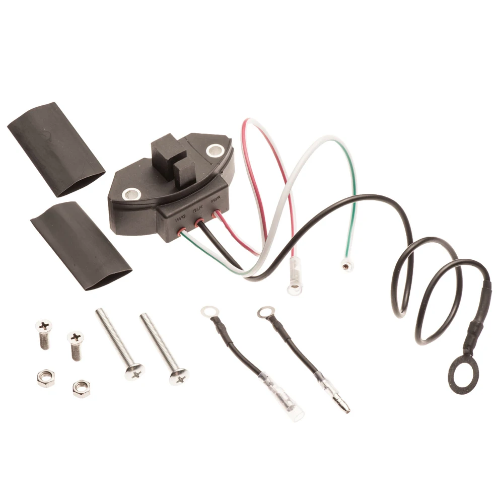
MERCRUISER THUNDERBOLT IV Ignition Module Wiring Harness V6 ...
How Mercruiser Thunderbolt ignition systems work ... Mercruiser Thunderbolt ignition systems. Mercruiser introduced the Thunderbolt IV onto their engines in 1982, alongside the introduction of the 1-R drives. The TB-IV system was used until the introduction of TB-V mid-way through 1996. Thunderbolt V was an improvement on an already exceptionally reliable and well performing system.
Service Bulletin
Thunderbolt IV wiring diagram - Offshoreonly.com Thunderbolt IV mounted on exhaust elbow wht/red from module to dis. wht/grn from module to dis. gray neg on coil to tac. and to module. purple on pos. coil from module and kill switch /ignition. blk. is ground .
MERCURY MERCRUISER 8.1S HO DIAGNOSTICS Service Repair Manual ...
Mercruiser Thunderbolt Iv Ignition Module Wiring Diagram ... Ignition sensor kit mercruiser thunderbolt i iv distributor. So from what i've read about the thunderbolt iv ignition . If there is spark, replace the ignition sensor in the dist. Find many great new & used options and get the best deals for w4 mercruiser thunderbolt iv module harness ignition v6 at the best online prices at ebay!

2 - Marine Office
TESTING THUNDERBOLT IV HEI IGNITION SYSTEM - Frequently ... How do I troubleshoot my Thunderbolt Ignition? Use a voltmeter when making these tests. Do not use a test light. Source: Mercury Marine Service Bulletin 92-11.

Buying Guide | Quicksilver Distributor Sensor 892150Q02 ...
Wiring Diagrams

I am repairing a 1988 mercruiser MCM 7.4 liter engine equiped ...

Mercedes W114 250ce Motorkabelbaum in Brandenburg - Temmen ...
Distributor & Ignition Components for Mercruiser (4.3l / 4.3 ...
Mercury Outboard Wiring diagrams -- Mastertech Marin
Hardin Marine - Wiring Harness-Electrical (Mounted On Exhaust ...
Delco Ignition System Wiring - Offshoreonly.com

A-Team Performance Marine Thunderbolt Ignition Sensor Kit Compatible with Mercruiser 18-5116-1 V-6 & V-8

Mercruiser Ignition Switch Wiring Diagram | Boat wiring ...
Ersatzteilkatalog

This question relates to a 1994 Mercruiser Alpha one,4.3L v6 ...

Buy 87-91019A3 Thunderbolt Ignition Sensor 87-892150Q02 ...
Delco Ignition System Wiring - Offshoreonly.com
CP Performance - Wiring Harness-Electrical (Thunderbolt V ...

WIRING HARNESS/ELECTRICAL(MOUNTED ON DISTRIBUTOR) TB IV ...

Buy 87-91019A3 Thunderbolt Ignition Sensor 87-892150Q02 ...

MerCruiser Thunderbolt IV & V Ignition Sensor

Mercruiser Thunderbolt IV distributor pickup sensor | eBay

TUNE UP MERCRUISER GEN+ VORTEC MPI 305 350 SPARK PLUG WIRE DISTRIBUTOR CAP ROTOR | eBay
MerCruiser Thunderbolt Ignition Sensor 87 91019A3 87 ...

Quicksilver Distributor Sensor 892150Q02 - Thunderbolt- for V ...

Used MerCruiser Parts – Tagged "Distributor Ignition Parts ...

Thunderbolt Ignition
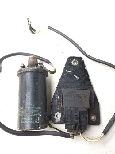
Sell Mercruiser V8 5.0 Thunderbolt IV Ignition Module 7e30a ...

Find Mercruiser Thunderbolt IV Ignition Module Wiring Harness ...
Mercruiser spark plug gap???? - The Hull Truth - Boating and ...

MerCruiser Thunderbolt IV Ignition Module 15248A1 for sale ...
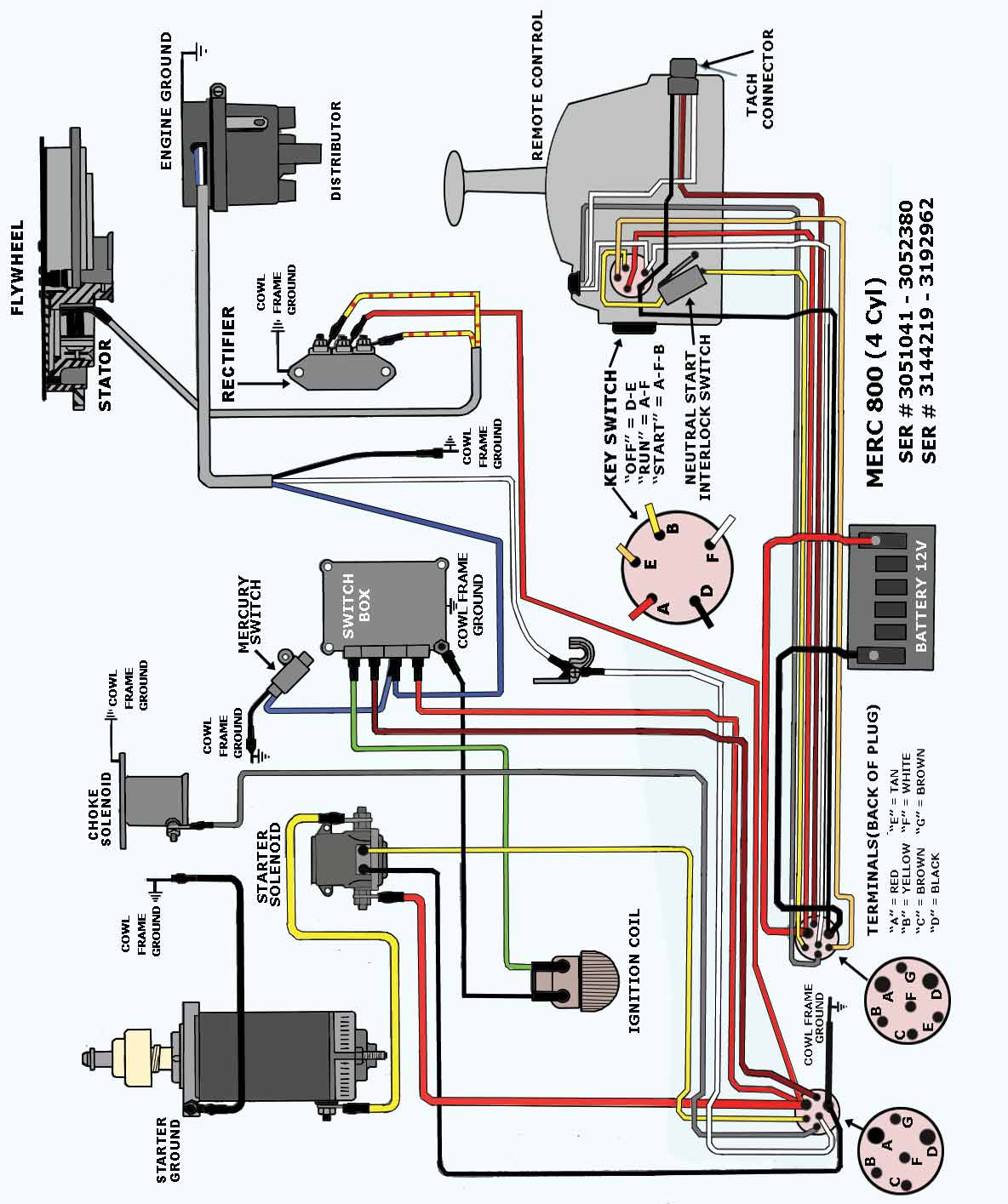
Mercury Outboard Wiring diagrams -- Mastertech Marin
0 Response to "40 mercruiser thunderbolt iv ignition module wiring diagram"
Post a Comment