42 two force member free body diagram
The free-body diagram shows the joggled crank (A-B) and the pedal (B-D) with the load being applied at a point halfway along the pedal (point C). More next time when we will attempt to calculate some stresses from the free-body diagrams derived here. In my old days at university the student would... 2/19/2014 4 Points to remember when drawing a free-body diagram (also on your handout) • Sketch the object, free of its surroundings. This may be as simple as a circle, square, or dot. • Draw force vectors such that their tails originate at the center of the object and the tip points away from this point.
From the free-body diagram of the entire beam we have the two balance equations. Free-body diagram of segment 2. Taking the second segment, ending anywhere before the second Also if the shear diagram is zero over a length of the member, the moment diagram will have a constant value...

Two force member free body diagram
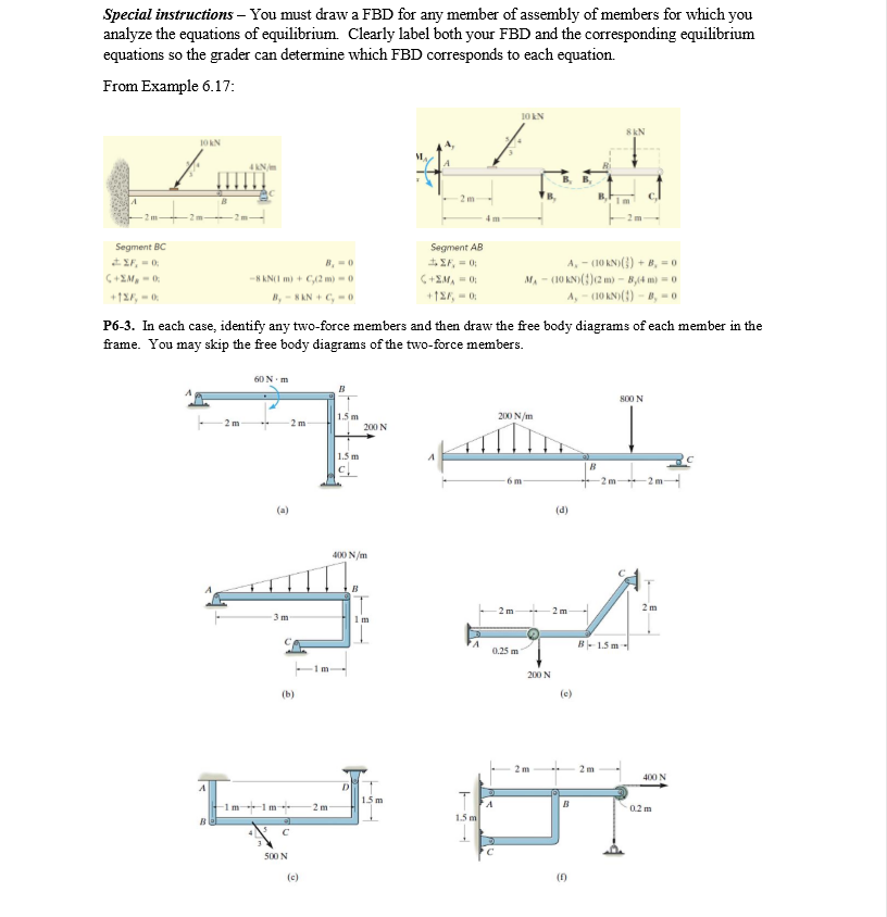
The member BC is a two force member. Show the free body diagram of the members of the frame as in Figure (5). Want to see more full solutions like this? Subscribe now to access step-by-step solutions to millions of textbook problems written by subject matter experts! Truss construction, fabricated from simple "two-force" members that could be easily replaced when Stiffness and flutter requirements refer to the fact that an aircraft must be free of excessive vibration diagrams, truss load calculation · Chapter 3 - Inertia loads and load factors · Chapter 4 - Introduction... Draw a free-body diagram for the object, including only the forces that act on it. When suitable, represent the forces in terms of their components in On the free-body diagram, indicate the location of the pivot and the lever arms of acting forces—you will need this for correct computations of torques.
Two force member free body diagram. When drawing a free-body diagram, the body. is isolated from its surroundings. That is, the surrounding objects are. Theorem 3.3 (Two-force member).If precisely two nonzero forces, and. no couple, act on a rigid body in static equilibrium, then those forces. TWO-FORCE MEMBERS A two-force member is a rigid body with no force couples, acted upon by a system of forces composed of, or reducible to, two forces at different locations. The most common example of the a two force member is a structural brace where each end is pinned to other members as shown at the left. In the diagram, notice that member ... Consider the following free body diagram of a two-force member. Inasmuch as the stress σ acts in a direction perpendicular to the cut surface, it is referred to as a NORMAL stress. Thus, normal stressed may be either tensile or compressive. Our sign convention for normal stresses is: Tensile stresses are positive (+) Determine the force in each member of the truss for a wind load equivalent to the two forces shown. State whether each member is in tension or compression. 2- For the frame and loading shown, draw the free-body diagram(s) needed to determine the force in member BD and the components of the...
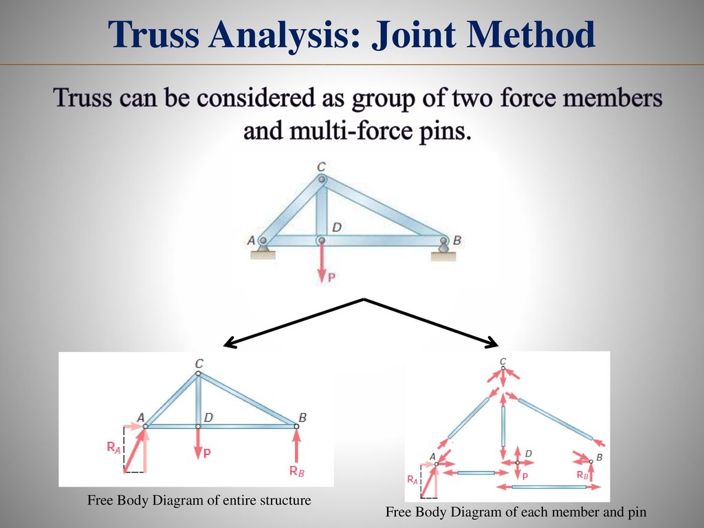
The free-body diagram for each individual mass is shown below. Each object is experiencing a downward force of gravity (Fgrav) Two-body problems like these three example problems can be quite a challenge. Having a systematic approach that is applied to every problem simplifies the analysis. With these two assumptions, the members act as two-force members. They are loaded in either tension or compression. the entire truss and determine the support reactions (typically using scalar equations of equilibrium). 2. Draw the free-body diagram of a joint with one or two unknowns. Interconnected Rigid Bodies with Multi-force Members • Rigid Non-collapsible. -structure constitutes a rigid unit by itself when removed from its Dismember the frame and draw a separate free-body diagram of each member 3.92-kN forces exerted by the shaft of the pulley on the member BF Free-Body Diagram. • Keep all external distributed loadings, couple moments, torques, and forces in their exact locations, before passing the section through the body at the point FBA 7750 N Since BA and BD are also two-force members, the free-body diagram FBD 4650 N of joint B is shown in Fig.
Free-body diagram of an object suspended from a stationary rope. Exam Tip. When labeling force vectors, it is important to use conventional and Free body diagrams are useful for modeling the forces that are acting on an object. Each force is represented as a vector arrow, where each arrow Begin with free-body diagrams isolating each piece of the frame as shown in the diagrams at the left. The free-body diagram of the quarter-circular arch shows that it is a two-force member. Thus, the reaction forces at pins A and B must be equal, opposite, and collinear. From geometry, it is known that F A and F B act at a 45° incline and F A = - F B. The free-body diagram of the beam shows that it is a three-force member. components of the force exerted at C on member BCD. SOLUTION: • Create a free-body diagram for the complete frame and solve for the support reactions. • Define a free-body diagram for member BCD. The force exerted by the link DE has a known line of action but unknown magnitude. It is determined by summing moments about C. This engineering statics tutorial explains what two force members are and how they can be used to solve frames, machines, and truss problems. Basically, if a...
Two-force member FBD | Download Scientific Diagram
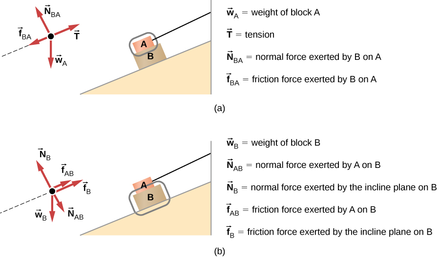
Example 8 : A system with two blocks, an inclined plane and a pulley. A) free body diagram for block m 1 (left of figure below) 1) The weight W1 exerted by the earth on the box. 2) The normal force N. 3) The force of friction Fk. 4) The tension force T exerted by the string on the block m1. B) free body diagram of block m 2 (right of figure below)
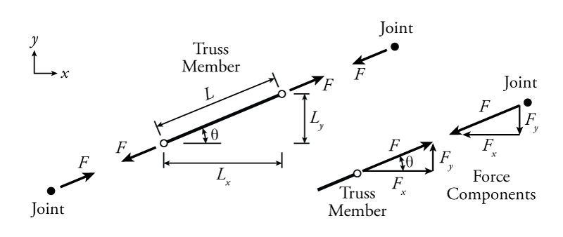
3.2 Calculating x and y Force Components in Truss Members ...
4. The links are two force members and are either in tension or compression. Analysis: 1. We first draw a free-body diagram of the entire structure. 45˚ 45˚ 1500 N 1500 N 45˚ 45˚ A D B C 1 1 1 2 2 A y Ax Dy 2. Taking moments about point A and assuming clockwise moments to be positive, A!M = 0 = 1500(2) + 1500(1) - D y(1) 3. Solving for Dy ...
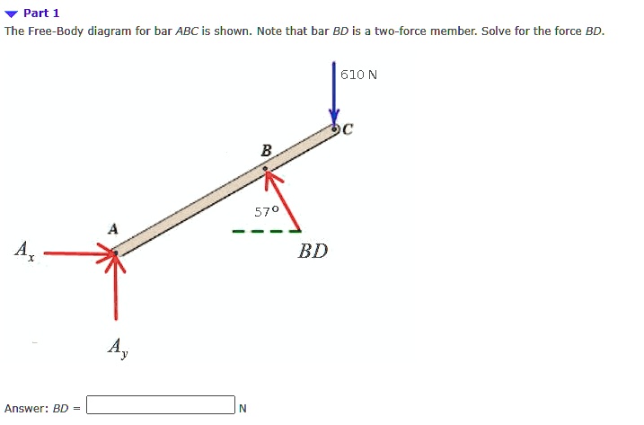
SOLVED:Part 1 The Free-Body diagram for bar ABC is shown ...
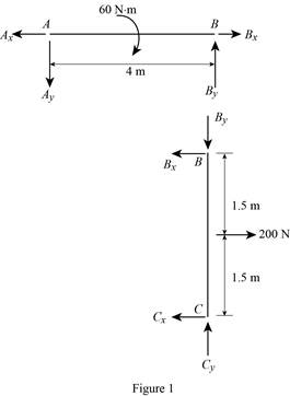
a) Identify any two-force members in the frame. b) Draw the overall free body diagram and the individual free body diagrams of members ACE and BCD, and pulley E. c) Determine the forces at pin C on member BCD.
Solved] The free-body diagram for rigid member ABC is shown ...
ladder truck • - no seatbelt Free-body diagrams Free-body diagrams are used to show the relative magnitude and direction of all forces acting on an object. This diagram shows four forces acting upon an object. There aren't always four forces, For example, there could be one, two, or three forces.

In each case, identify any two-force members, and then draw ...
(Free Body Diagram) Two-force member 1 : ACDE. 2 : (Two Force Member) CBA (Three Force Member) BD.
5.7 Drawing Free-Body Diagrams | University Physics Volume 1
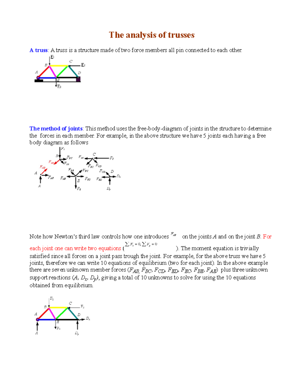
Each truss member act as a two-force member, and therefore the force acting at each end of the member will be directed along the axis of the If not, always assume the unknown member forces acting on the joint's free-body diagram to be in tension; i.e., the forces "pull" on the pin.
Concept on two-force member - Engineering Stack Exchange
Therefore, it is a two-force member, and the direction of the total force, RA, acts along the member itself. Then RAy and RAx are the rectangular Then create the free-body diagram for the horizontal part by breaking it through the pin and replac-ing the removed part with the internal force and moment...
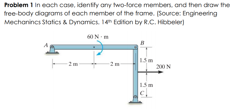
Answered: Problem 1 In each case, identify any… | bartleby
Draw a free-body diagram to show the forces acting on an object. Show Step-by-step Solutions. One force has a magnitude of 10N and the other force has a magnitude of 8N. The angle between the two forces is 30°. Draw a vector diagram to find the resultant force.
STATIC FORCE ANALYSIS
(Redirected from Kinetic diagram). A free body diagram consists of a diagrammatic representation of a single body or a subsystem of bodies isolated from its surroundings showing all the forces acting on it In physics and engineering, a free body diagram (force diagram, or FBD)...
STATIC FORCE ANALYSIS
The free body diagram of the system can be seen in the diagram below. The magnitude and the line of action of the force at F, 10 Kips, is known. and opposite to the force C of the two-force member CB. The line of action of the forces at point F and point C intersect at X. The line of action (Why is this?)

Statics eBook: Two- and Three-Force Members
3 Outline Application Definition Free Body Diagram Free Body Diagram exercises Reaction supports Two-force & 3-force. 60 EXAMPLE OF TWO-FORCE MEMBERS In the cases above, members AB can be considered as two-force members, provided that their weight is neglected.
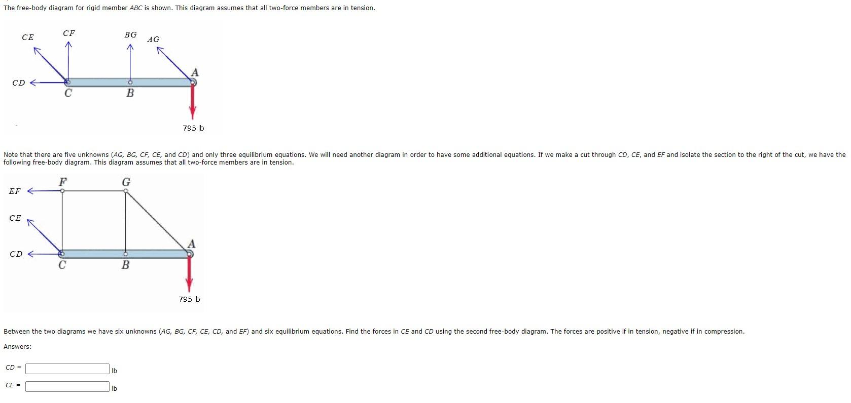
Solved The free-body diagram for rigid member ABC is shown ...
TWO-FORCE MEMBERS & THREE FORCE-MEMBERS (Section 5.4) The solution to some equilibrium problems can be simplified if we recognize members that are subjected to forces at only two points (e.g., at points A and B). If we apply the equations of equilibrium to such a member, we can quickly determine that the resultant forces at A and B must
Analysis of Trusses - lecture notes - ME 273 - Statics - BU ...
Statics of Non-Concurrent Force Systems. Supporting a Rigid Body | Free-Body Diagram of a Rigid Body. Two-Force Members: When ...
ME 141 Engineering Mechanics Portion 4 Analysis of Structure ...
Free Body Diagrams of Rigid Bodies; 2-D Equilibrium. W. Example of a free body diagram. Two-o r -Three-Force Members. These are two major equilibrium situations. often encountered.

TRUSSES: Method of Joints (MOJ) | Structures of Two Force Members | Identifying Zero Force Members
Lecture 7: Degrees of Freedom, Free Body Diagrams, and Fictitious Forces. Free body diagrams with two bodies. Flash and JavaScript are required for this feature. This recitation reviews free body diagrams and covers a problem with a torsional spring pendulum followed by a second problem with...
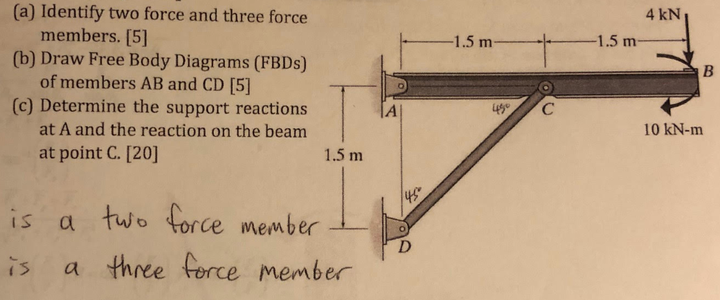
Solved 4 KN -1.5 m- -1.5 m- B (a) Identify two force and ...
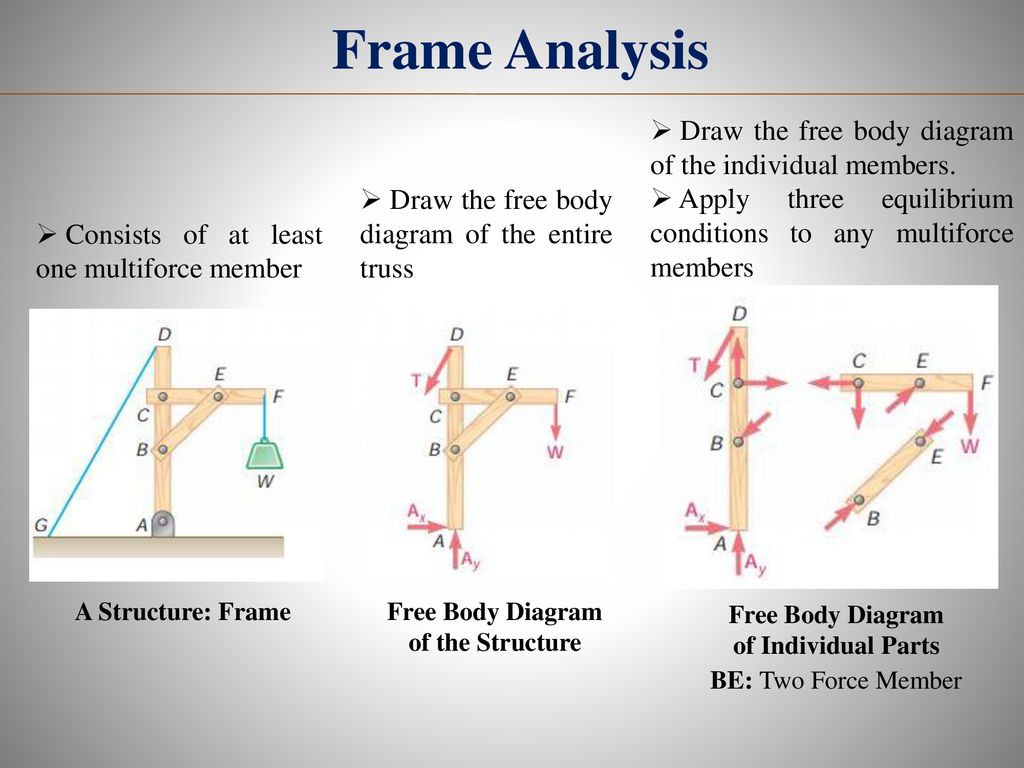
A free body diagram of the complete frame is used to determine the external forces acting on the frame. • Internal forces are determined by dismembering the frame and creating free-body diagrams for each component. Analysis of Frames • Forces on two force members have known lines of action...

Analysis of Frames Two force members A twoforce
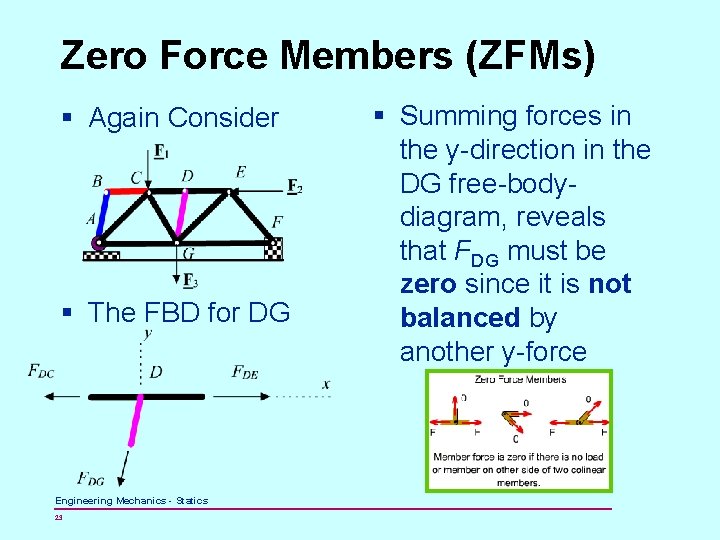
¤ The free-body diagram of joint C indicates that the force in each member must be zero in order to maintain equilibrium. The free-body diagram of member GC can be obtained by considering the section b-b, Moments will be summed about point A in order to eliminate the unknowns FHG and FCD.

In each case, identify any two-force members, and then draw ...
Frames and Machines Interconnected Rigid Bodies with Multi-force Members Rigid Non-collapsible structure constitutes a rigid unit by itself when 5 Frame Analysis Collapsible frame Overall free body diagram Necessary condition to obtain support reactions Not sufficient condition Member free body...
Example 2
043 - Free-Body DiagramsIn this video Paul Andersen explains how free-body diagrams can be used to solve kinematics problems. The only two parts of a...
Document
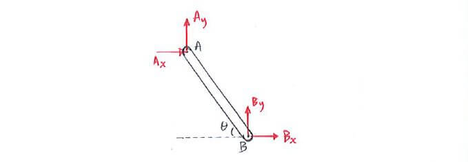
Free-Body Diagram: A diagram of a body (or a part of it) which shows all the forces and couples applied on it, and which has all the forces and A two-force member can only be in equilibrium if the line of action of the resultant of the forces at each point passes through the other point, and each...
Solved Identify any two-force members, and then draw the ...
A Free or Force Body Diagram (FBD), is a pictorial device, often a rough working sketch, used by engineers and physicists to analyze the forces and moments (torques) acting on the body. Concurrent forces: When two or more forces act on the same point at the same time. Resultant force: A single...
Ch2-final-v3 copy 2
Two force members, The geometry of two force members; free body diagrams; Equations of equilibrium; Equal and opposite forces; We will work through a sequence of steps that is transferable to multiple real world problems. The steps include: STEP 1: Identifying two force members STEP 2: Drawing free body diagrams of each component
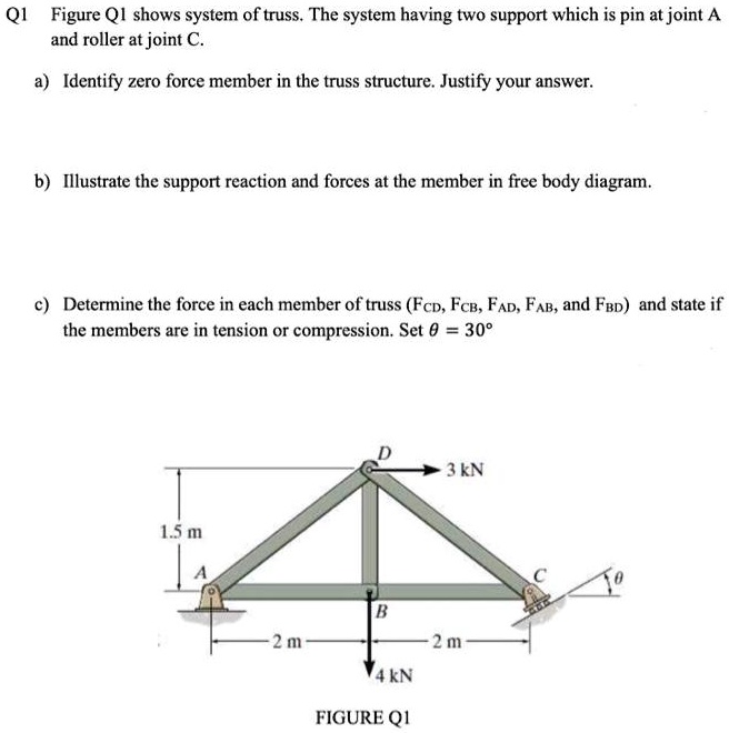
SOLVED:Q1 Figure QI shows system of truss. The system having ...
Free body diagram of a body is the diagram, which is drawn by showing all the external forces and support reactions on the body and by removing If P and Q are the two forces acting on a particle at A, then their combined effect can be replaced by a single force R. Where R is called as the resultant...
Free body diagram - Wikipedia
Draw a free-body diagram for the object, including only the forces that act on it. When suitable, represent the forces in terms of their components in On the free-body diagram, indicate the location of the pivot and the lever arms of acting forces—you will need this for correct computations of torques.
Two-force members | C3.1 Introduction to Plane Trusses | Statics
Truss construction, fabricated from simple "two-force" members that could be easily replaced when Stiffness and flutter requirements refer to the fact that an aircraft must be free of excessive vibration diagrams, truss load calculation · Chapter 3 - Inertia loads and load factors · Chapter 4 - Introduction...
Chpapter 5 TRUSSES FRAMES AND MACHINES Engineering Mechanics
The member BC is a two force member. Show the free body diagram of the members of the frame as in Figure (5). Want to see more full solutions like this? Subscribe now to access step-by-step solutions to millions of textbook problems written by subject matter experts!
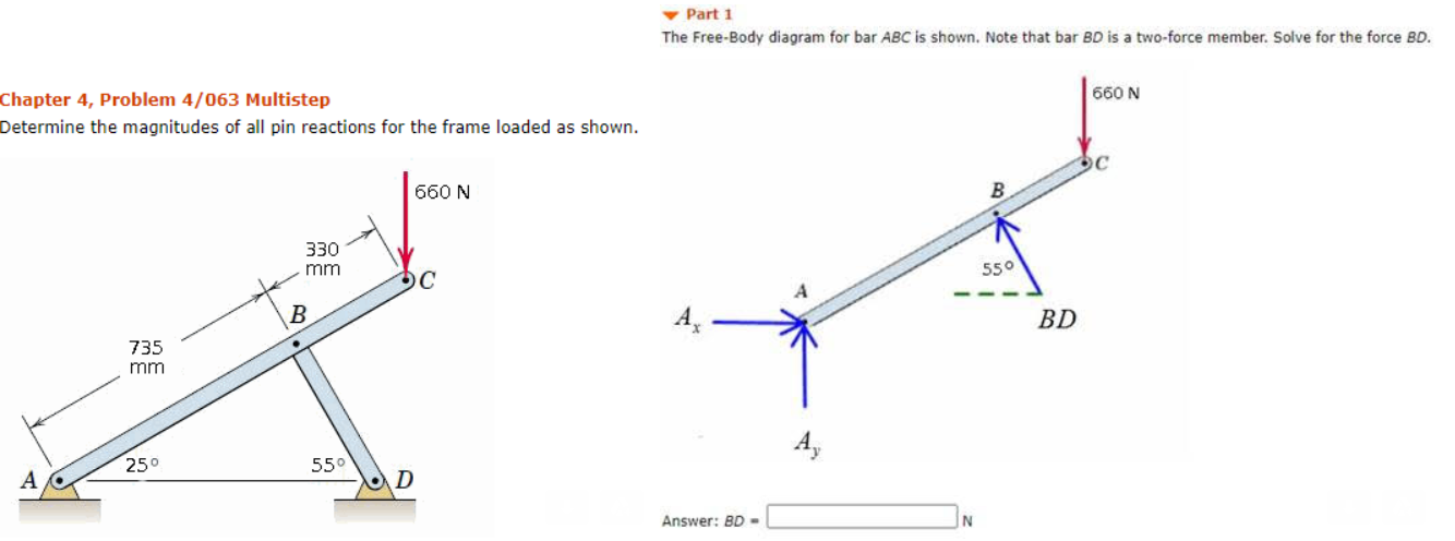
Solved Part 1 The Free-Body diagram for bar ABC is shown ...

Statics eBook: Two- and Three-Force Members
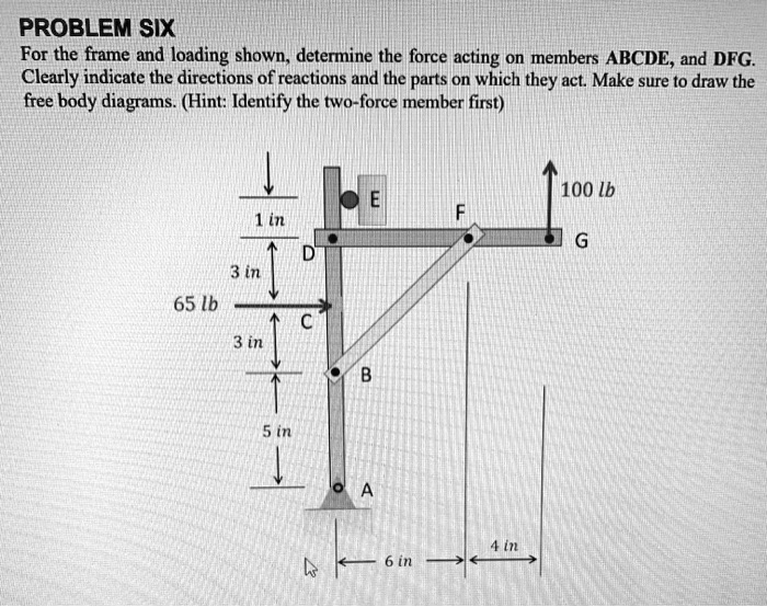
SOLVED:PROBLEM SIX For the frame and 'loading shown_ ...
F Pin B F Pin B

Chapter Objectives Chapter Outline Rigid body diagram FBD and ...
Three-Force Member Example Problem
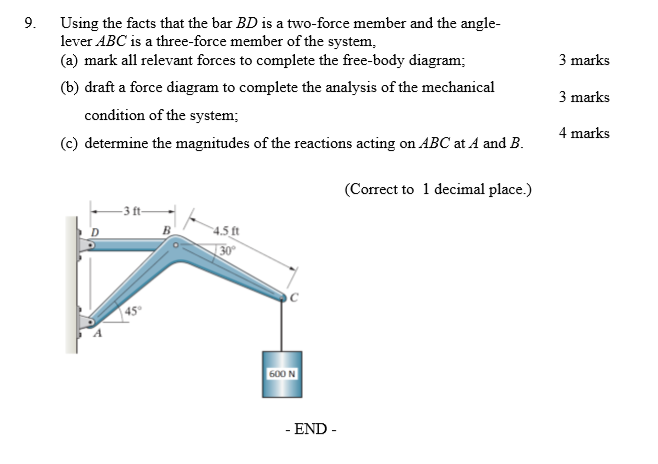
Solved 9. 3 marks Using the facts that the bar BD is a ...
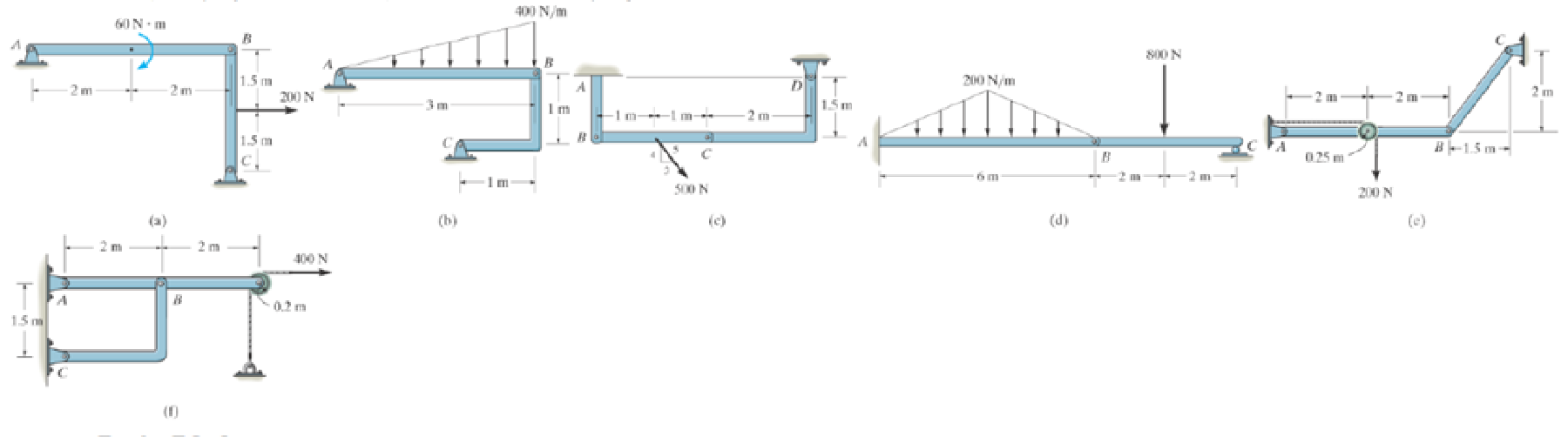
In each case, identify any two-force members, and then draw ...
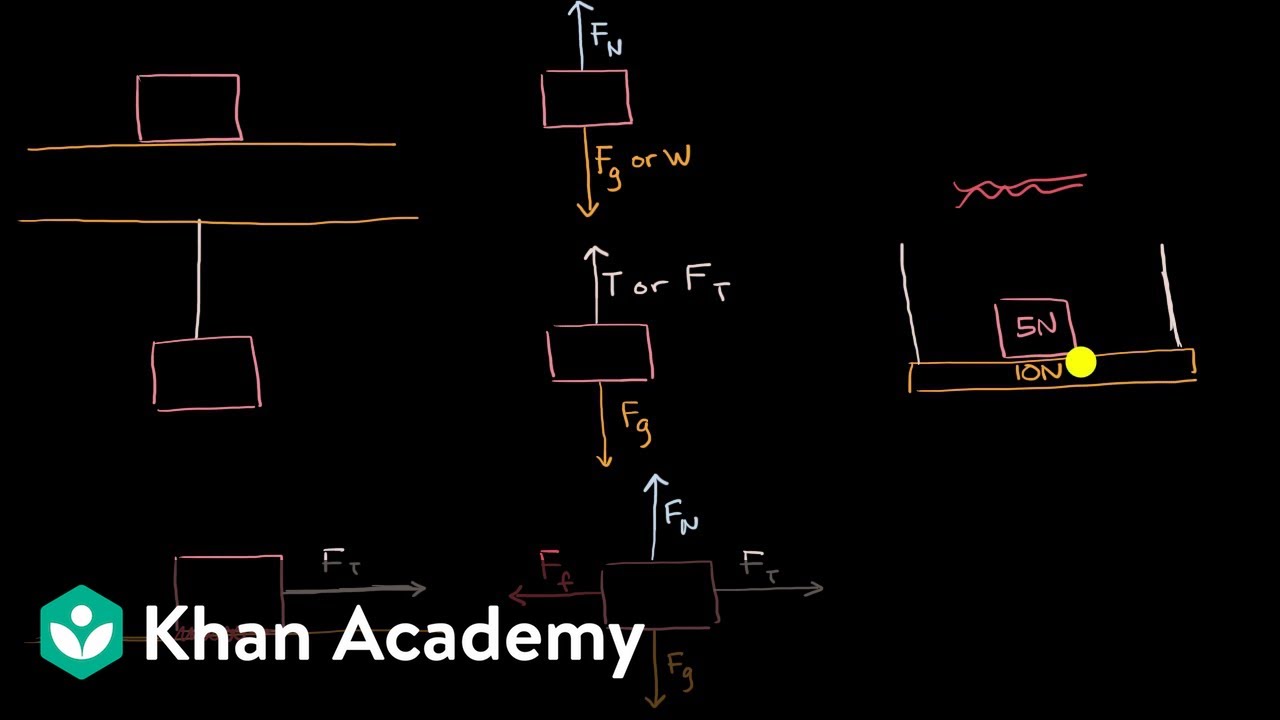
Types of forces and free body diagrams
In each case, identify any two-force members, and then draw ...
Solved 1) Please give equilibrium equations for all members ...
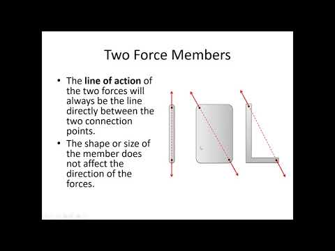
5.2: Two-Force Members - Engineering LibreTexts
ME 245 Engineering Mechanics and Theory of Machines Portion 4 ...

What Is Zero Force Member for Truss | How to Identification ...

Two-force member FBD | Download Scientific Diagram
TRUSSES Learning Objectives 1). To identify zero-force ...
0 Response to "42 two force member free body diagram"
Post a Comment