42 pv system grounding diagram
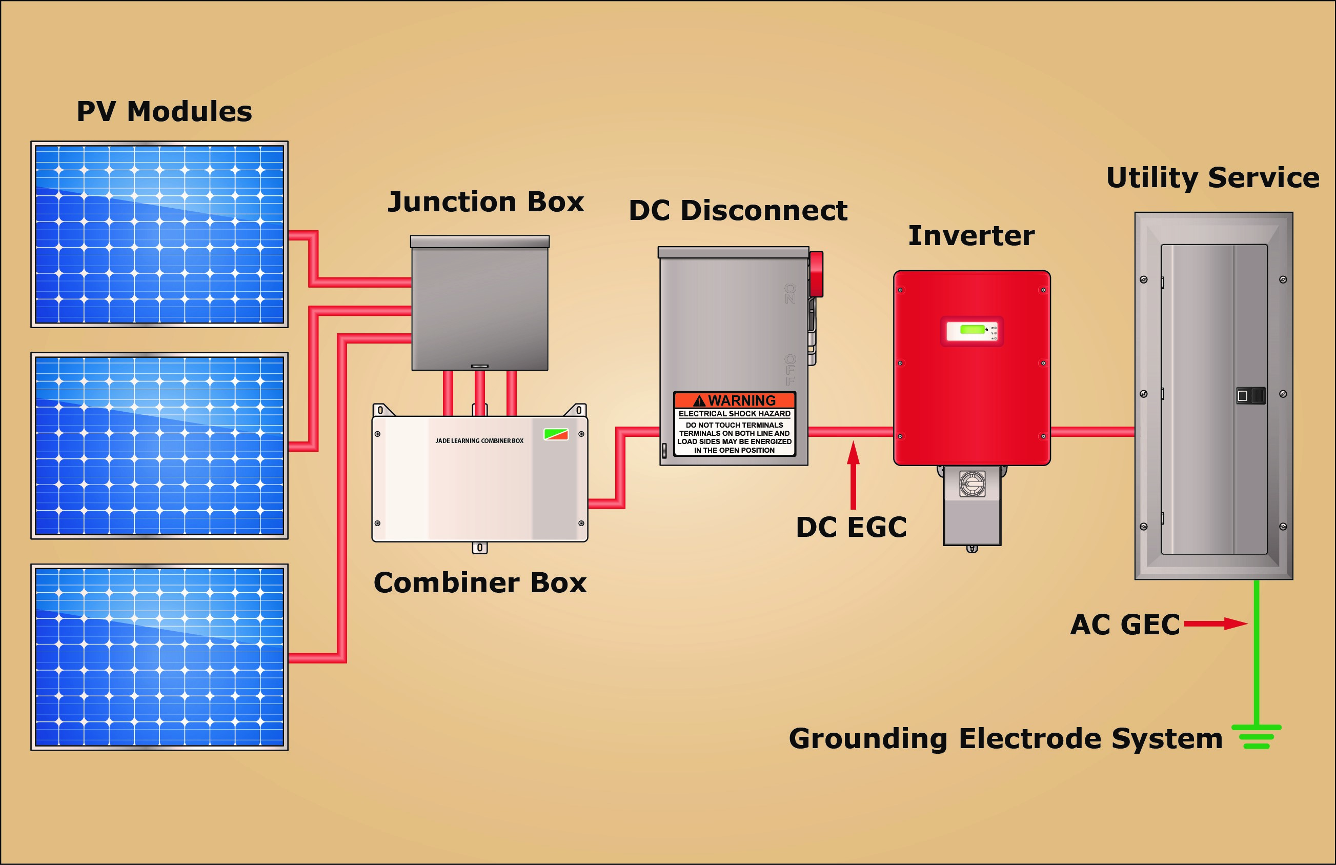
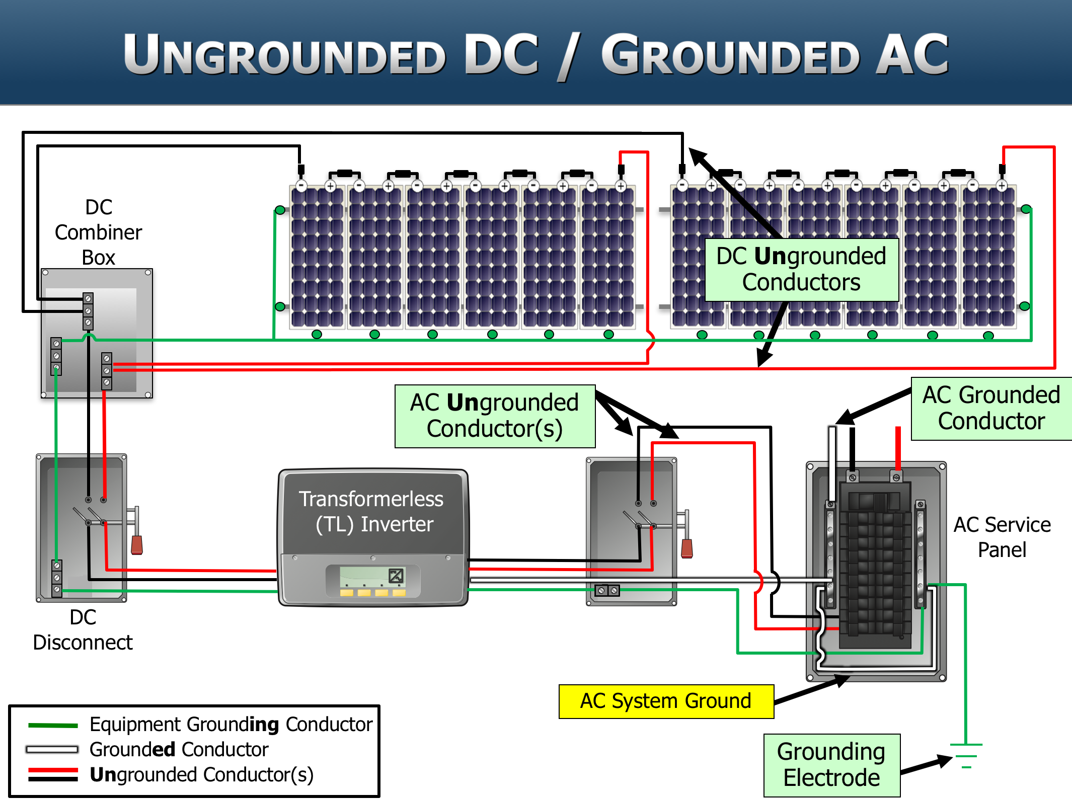
Installation Practices: Keep Your PV System Well-Grounded System Ground vs. Equipment Ground: The National Electrical Code (NEC) requires that all PV Systems over 50 V have one current-carrying conductor connected to ground (690.41). The connection between that conductor (either the positive or negative DC conductor as well as the neutral conductor if the system has an AC component) and the earth is the system ground. Grid Connected Photovoltaic Systems - an overview ... A general system diagram of grid-connected PV systems is shown in Fig. 6.6 and consists of three main components: PV panels (or arrays), power converters (PV inverters), and ac grid. As the power generated by the PV arrays is dc power, the power converter, which is a power electronic-based technology, is required to convert the dc power from ...
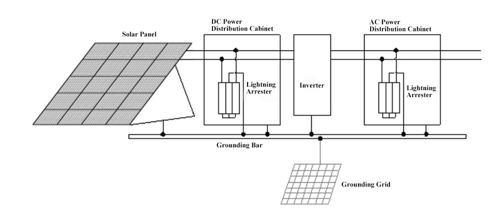
Solar Lightning Protection: PV system grounding and ... For small solar systems, you can implement grounding by inserting a 8-feet long metallic ground rod, made up of conductive material like copper or aluminum, into the earth.After you connect all conductive parts of the system to this rod with the help of thick wires.For larger systems, it is a good idea to create a grounding grid.A grounding grid is an interconnection of several ground rods, approximately 10 feet apart from each other and connected by the help of a bare copper conductor ...

Pv system grounding diagram
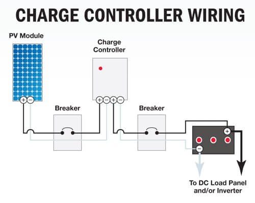
PDF Photovoltaic System Grounding - Solar ABCs The equipment in direct current (DC) portions of the PV system may be grounded using conductors as outlined above with appropriate connections to each metal surface. In general, when a copper wire is connected to a metal surface to be grounded, some sort of certified/listed grounding device must be used. PDF PV Grounding REQ's - CE Grid-tied PV System Grounding Electrode Conductor Requirements A grounding electrode conductor is required per NEC 690.47 from the inverter to the existing building grounding electrode conductor. NEC 690.47(C)(3) allows for a single conductor to serve as both equipment ground as well as the bond between AC and DC systems for inverters with a DC Solar Power System Diagram | 4 Basic Building Blocks Solar power systems vary widely in their power producing capabilities and complexity. But I wanted to sketch a simple basic solar power system diagram that shows the building blocks. Regardless of a given system's capacities and specifications, there's a common thread among most of them: The basic building blocks of its major components. 1.
Pv system grounding diagram. PDF Installing and Inspecting Solar Photovoltaic (Pv) Systems Ground-Fault Protector AC Fused Switch DC Fused Switch Block diagram of PV system with battery backup PV Array PV Array Circuit Combiner Ground-Fault PV Array Protector Switch Backup Power System, DC/AC Inverter, and Battery Charge Controller Main Service Panel Utility PDF Ground-fault Photovoltaic Analysis and - Mersen ground-fault PV array are summarized as below. • At the positive busbar: I pv+ = -I back +I 2+ +…+I n+ • At the negative busbar: I pv-= I 1-+I 2-+…+I n-• At the ground-fault point F: I g =I back + I 1-, where I 1-= I sc • At system grounding point G: I pv+ + I g = - I-V Characteristics Analysis under Ground-Fault Condition PDF Scope (1) Grounding of solar photovoltaic system output ... Diagram B2 shows the parallel connection of solar photovoltaic systems where the PV system is indirectly connected to the supply authority, on the load side of the service box. The utility disconnecting means is not required to be an approved service box. Rule 10-210 d) requires the grounded conductor of a solidly grounded ac system supplied by PDF Micro-Inverter Electrical Diagram - Franklin County, Ohio ARRAY GROUNDING AC COMBINER PANEL G ____ MICRO-INVERTERS IN BRANCH-CIRCUIT. Expedited Permit Process for PV Systems 5 Contractor Name, Address and Phone: Notes for One-Line Standard Electrical Diagram for Single-Phase PV Systems Site Name: Site Address: System AC Size: SIZE FSCM NO DWG NO REV E1.2a SCALE NTS Date: SHEET Drawn By: Checked By:
Schematic diagram of (a) grounded and (b) ungrounded PV ... Download scientific diagram | Schematic diagram of (a) grounded and (b) ungrounded PV systems. PDF FFECTIVE GROUNDING FOR PV PLANTS - Solectria b) Vector Diagram Figure 2. Single-Line-to-Ground Fault on a System with a Grounded Transformer Figure 2 shows a similar vector diagram on a solidly grounded system with the same single-line-to-ground fault applied on phase A. The transformer neutral is tied to ground solidly so that the neutral PDF Inspecting Photovoltaic (Pv) Systems for Code-compliance Step 2: Electrical Review of PV System (Calculations for Electrical Diagram) • In order for a PV system to be considered for an expedited permit process, the following must apply: 1. PV modules, utility-interactive inverters, and combiner boxes are identified for use in PV systems. 2. The PV array is composed of 4 series strings or less, and 15 kW. STC. or 2017 PV System Plan Check Worksheet PDF - Palmdale, CA Worksheet for PV System Plan Check Supplied Diagrams _____ Is a basic site diagram supplied with the permit package? Location of major equipment identified on plan. _____ Is a one-line diagram supplied with the permit package? _____ Array configuration shown _____ Equipment grounding specified
PDF Solar Photovoltaic (PV) Systems PV systems. An off-grid solar PV system needs deep cycle rechargeable batteries such as lead-acid, nickel-cadmium or lithium-ion batteries to store electricity for use under conditions where there is little or no output from the solar PV system, such as during the night, as shown in Figure 3 below. 1.3 Solar PV Technology What is the process of grounding and bonding a solar PV array? It also limits the voltage-to-ground that can occur on normally non-current-carrying metal components, ranging from frames and rails to conduit and enclosures. "Bonding and grounding PV systems ensures public safety, as well as the safety of PV installers and field electricians," said Andy Zwit, Codes and Standards Manager at ILSCO. PDF PV Ground Referencing Reqs and Calcs V1 4 For simplicity, the example online diagrams below exclude system components not relevant to grounding requirements; these drawings are not intended to be used as example onelines for system design. Example 1 - Separate Zig‐Zag Grounding Transformer A PV facility with 1 MVA inverter total AC nameplate is interconnected to a 13.8kV feeder PDF Solar Photovoltaic (PV) System Components On a solar PV system, the ungrounded conductor is usually the positive (+) conductor. The negative (-) conductors are grounded, and a ground conductor bonds the system to an . electric ground, as required by the local electrical code. Local utilities may require disconnects accessible by utility personnel on a grid-connected PV system.
Solar Panel System Grounding To Earth
Photovoltaic PV design and One Line Diagrams Made Simple TPVS DWG is an Microsoft Access® database application to bring module, inverter and site specifications together, perform complex calculations and present a diagram or drawing as part of a concept system for an owner, builder, electrician, utility or authority having jurisdiction(AHJ) approvals. Simple to use, inexpensive, effective. Version 1.1

Grounding and your solar system - Solar Power - Power Forum ...
Pv Grounding Diagram - smdo190022 fig4 Smdo190022 Fig4. Pv Grounding Diagram. 1967 camaro electrical diagram 2000 subaru forester radio wiring diagram 2015 dodge ram wiring diagram 89 nissan 240sx interior panel monarch lathe wiring diagram empty fuse box xc90 91 jeep wrangler fuse box layout farmall cub hydraulic pump diagram 65 corvette radio wiring tundra trailer wiring harnes removal 1999 ford contour fuse box layout 1995 ford ...

Photovoltaic Protection -PV Protection-Solutions Board-ADLER ...
Schematic diagrams of Solar Photovoltaic systems - Wattuneed Schematic diagrams of Solar Photovoltaic systems. You have Decided to install your PV system yourself goal you do not know where to start. We carried-out wiring diagrams of the several different Elements of a photovoltaic solar system.

Example of a simple off-grid (or marine or vehicle based ...
Stand-Alone Photovoltaic Systems - ScienceDirect An inverter may also be included in the system to convert the direct current generated by the PV modules to the alternating current form required by normal appliances. A schematic diagram of a stand-alone system is shown in Figure 9.17. As can be seen, the system can satisfy both DC and AC loads simultaneously.

Off Grid Solar System: Wiring Diagram, Design, Sizing
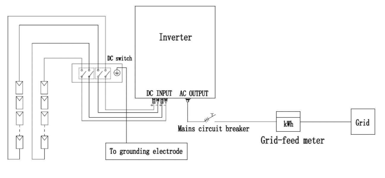
Wiring a Home Solar Photovoltaic (PV) System To help you visualize how a home grid-tied PV system is wired, here's a diagram posted online by a do-it-yourselfer: This circuit includes DC and AC disconnects, and a grounding wire ("GND 6 AWG Bare"). The schematic identifies fuses, wire sizes, voltages, amps and the array size ("2760 WATT DC PV").
Grounding Systems Permitted to Be Connected on the Supply ...
PDF Guide to the installation of PV systems - BRE GUIDE TO THE INSTALLATION OF PV SYSTEMS 1.0 INTRODUCTION 1.1 Scope The scope of this document is to supply system installers with information to ensure that a mains-connected PV system meets current UK standards and best practice recommendations. It is primarily aimed at small-scale installations (less than 16A per phase, as per the scope of ER G83/1).
What is PV MPPT and how does it work? What does it do ...
PDF PV System - Geyserwise PV Bat Pump Ground Battery 3 - LDR - outside Set voltage on MPPT 300W PV panel 300W PV panel 300W PV panel 11 2 1 CN5C RT GeyserWise control Thermostat PTC element White DC Blue DC Black AC Red AC + - + - + - 4 4 01 Isolator switch L1 N1 GL 2N 2 + PV Bat (red) Pump (green) Ground (purple) System overview - 150L for high irradiation ...

Schematic diagram of (a) grounded and (b) ungrounded PV ...
PDF PV Ground - Off Grid & Grid-Tied Solar Power Systems Electrical systems in the U.S. (including PV systems) are generally solidly grounded to limit the voltage with reference to ground during normal operation, and to prevent excessive voltages due to surges from lightning or unintentional cross connections with higher voltage lines. In PV systems, the modules are usually mounted in high,

Solar Array Grounding System With Lightningproof Grounding ...
Grounding in Off-Grid Solar Systems - SunWize | Power ... Introduction to Grounding Basics. There are three main reasons for grounding in an off-grid power system: safety, voltage transients, and the sheer fact that they are required for some loads. But before we address each of these, it's important to understand the actual definition of 'ground'. There are two types of ground: chassis (or mechanical) ...

How to test Photovoltaic bypass diodes, PID and voltage
PDF One Line Diagrams - Dickson Electric System This diagram shows a typical installation and does not include all PV system components. Grounding connections are not shown for simplicity. It should not be used for design purposes. 3. All PV systems are to be in compliance with the NEC, UL, IEEE 1547, and any other equivalent or applicable local, state or national governing requirements. 4.
GFPD Wiring - Victron Community
Solar Power System Diagram | 4 Basic Building Blocks Solar power systems vary widely in their power producing capabilities and complexity. But I wanted to sketch a simple basic solar power system diagram that shows the building blocks. Regardless of a given system's capacities and specifications, there's a common thread among most of them: The basic building blocks of its major components. 1.

How to make lightning protection design of residential PV ...
PDF PV Grounding REQ's - CE Grid-tied PV System Grounding Electrode Conductor Requirements A grounding electrode conductor is required per NEC 690.47 from the inverter to the existing building grounding electrode conductor. NEC 690.47(C)(3) allows for a single conductor to serve as both equipment ground as well as the bond between AC and DC systems for inverters with a DC
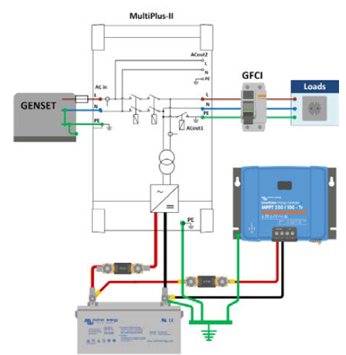
PV System Grounding and GFPD Application - Victron Community
PDF Photovoltaic System Grounding - Solar ABCs The equipment in direct current (DC) portions of the PV system may be grounded using conductors as outlined above with appropriate connections to each metal surface. In general, when a copper wire is connected to a metal surface to be grounded, some sort of certified/listed grounding device must be used.
_Solar%20panel%20wiring%20diagram%20-%20large.jpg)
How to wire solar panels | Knowledge Centre | Essentra ...

Safety issues in PV systems: Design choices for a secure ...

How to make lightning protection design for residential PV ...

Schematic diagram of (a) grounded and (b) ungrounded PV ...
SEI's PV101 and PV203 courses in perfect alignment with ...

How to incorporate floating batteries into a grounded solar array

Checking the PV System for Ground Faults
What are Main Components of a Solar PV System? | inverter.com

Electrical Wiring Diagrams From Unbound Solar | Electrical ...

Schematic diagram of the underwater grounding electrode array ...
Photovoltaic System Grounding

Safety issues in PV systems: Design choices for a secure ...
Solar PV System For Home - Sunflower Solar
Solar Photovoltaic (PV) Systems | UpCodes

How to Ground Solar Panels Correctly

6 String PV Combiner Box 10A Breaker for Solar Panel Off Grid ...

The Future of Solar Power Plants is Bright with Smart DC ...
Components of a Photovoltaic System

Off-Grid Solar Battery System Bonding and Grounding - Solar ...

Safety issues in PV systems: Design choices for a secure ...
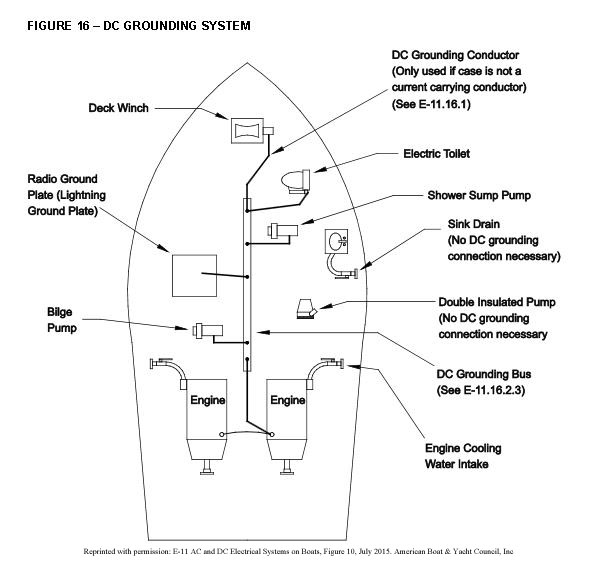
Grounding Solar PV Systems On A Boat - e Marine Systems

How to make lightning protection design for residential PV ...

Bonding and Grounding PV Systems - IAEI Magazine

Schematic diagram of (a) grounded and (b) ungrounded PV ...
Photovoltaic System Grounding

Large Scale Grid Solar Power Station System - Wind ...

Safety issues in PV systems: Design choices for a secure ...

Impact of grounding fault in PV modules on AC side and the ...
Installation Practices: Keep Your PV System Well-Grounded
0 Response to "42 pv system grounding diagram"
Post a Comment