42 ph diagram for refrigeration cycle
Video showing the 'ph' diagram and how it relates to the refrigeration cycle. rabbit warren diagram; rankine cycle ph diagram; rational numbers venn diagram; razor scooter wiring diagram; refrigeration cycle ph diagram; remington speedmaster 552 parts diagram; rikki tikki tavi plot diagram; rsx fuse box diagram; ruger 10 22 trigger assembly diagram; ruger mkii parts diagram; rule automatic bilge pump wiring diagram; rv ...
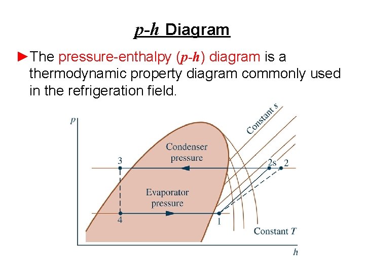
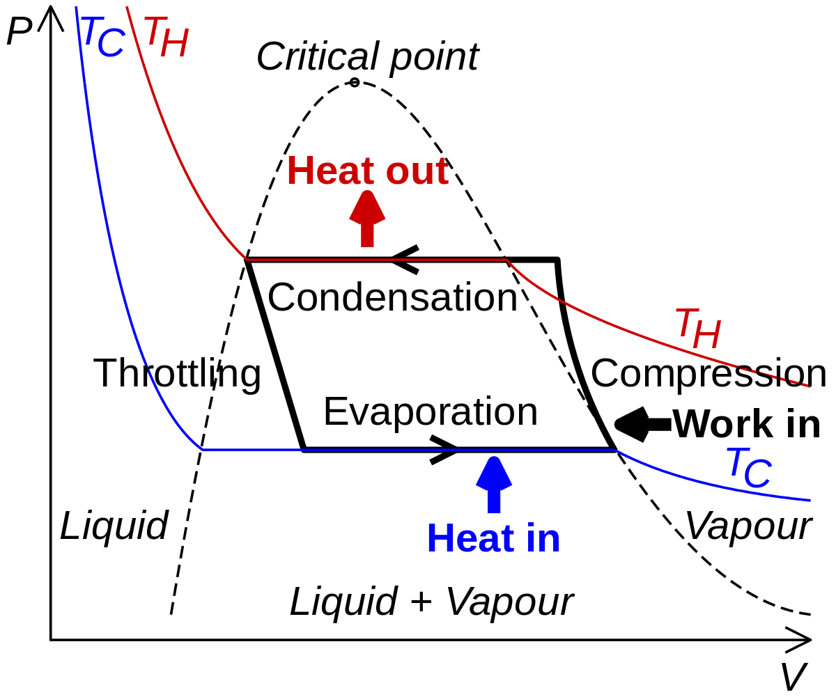
The refrigeration cycles can also be represented in a P-H diagram. Figure 5: P-H diagram representation of a dry refrigeration cycle Refrigerant fluid choice: We now turn our attention to the fluids. Usually, one tends to pick pL as low as possible, but not below atmospheric pressure. Thus, the refrigerant chosen needs to have a normal boiling ...

Ph diagram for refrigeration cycle
March 20, 2018 - When you can draw a refrigeration cycle on a p-h diagram, you can easily obtain the refrigerant characteristics through the diagram. Let's study about "How to draw a refrigerant cycle" in series, using the documents with courtesy of Mr. Yoshihiro, UDAGAWA, Toshiba-Carrier Corporation. Represent the refrigeration cycle on a P-h diagram c. Determine the quality of the refrigerant at the evaporator inlet d. Determine the refrigeration load e. Determine the COP and EER of the refrigerator f. Compute the theoretical maximum refrigeration load for the same power input to the compressor Water 18°C 26°C 1.2 MPa 65°C 42°C ... The cycle with extraction from the gas-cooler outlet (GCO) is represented as point A in Figure 1 and the ph diagram in Figure 2, the extraction from the exit of the subcooler as point B in Figure 1 (SCO) and Figure 3 and from the liquid tank (TNK) as point C in Figure 1 and Figure 4. Download : Download high-res image (322KB)
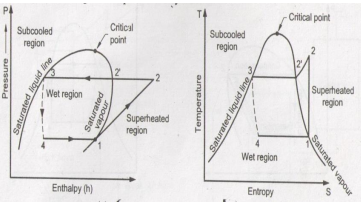
Ph diagram for refrigeration cycle. The log p-h diagram for refrigerant The refrigeration cycle For operating media which can have different phases, such as water or refrigerant, theT-sdiagram looks different. It has an area on the left (grey),in which the operating medium is liquid and supercooled. In the centre(blue) there is a mixture of steam and liquid, the wet steam. The log p-h diagram shows the thermodynamic state vari- ables in the respective phase. • pressure p. • specific enthalpy h. • temperature T. • specific volume v. Refrigeration cycle: In a refrigeration cycle, ... The figure shows the VCRS cycle without and with subcooling on P-h and T-s coordinates. It can be seen from the T-s diagram that without subcooling the throttling loss is equal to the hatched area b-4'-4-c, whereas with subcooling the throttling loss is given by the area a-4"-4'-b. ... Schematic diagram of joule-Thomson refrigeration (single MR) cycle. The specific working principle of single MR refrigerators is as follows. The refrigerant vapor sucked by the compressor flows into the aftercooler in a state of high temperature and high pressure through the compression process (1-2a).
Solution Sketch the pressure-enthalpy diagram of the cycle as in Fig. 16-12 b. The discharge pressure of the low-stage compressor and the suction pressure of the high-stage compressor are the same as the pressure in the 5°C evaporator. Next determine the enthalpies at the state points. hx = hg at -30°C = 1423 kJ/kg h2 = h at 517 kPa after ... The Refrigeration Cycle – Complete: In this final diagram of the refrigeration cycle we have introduced 3 new terms: Superheated, Saturated & subcooled. SUPERHEAT – Is an amount of heat added to refrigerant vapour beyond its boiling point. This ensures the refrigerant is in a gas state with no liquid present. R22 P/H Diagram * Diagram created using REFPROP – NIST Reference Fluid Properties As can be seen, the critical point of R-22 is more than 200°F, placing it well above the operating conditions of typical refrigeration systems. This can be contrasted with the CO 2 PH diagram, with a critical point of 88°F. Please note this is an ideal refrigeration diagram. There is no superheat exiting the evaporator or subcooling exiting the condenser. For a more detailed explanation of the P-H diagram, please refer to Sporlan Form 5-200 in our website's literature section under HVACR Educational Material. Figure 1. Condenser:
Refer to the P-H diagram for Ammonia in English units, This P-H diagram shows the Ammonia saturation The basis for the following calculations is 1 Ton of refrigeration, QL = 12,000 Btu/hr The solar collector provides steam that condenses at atmospheric pressure in the generator to provide heat. The optimum intermediate pressure for the two-stage refrigeration cycles is determined as the geometric mean between evaporation pressure (pl) and condensing pressure (ph, Fig. 11-79): based on equal pressure ratios for low- and high-stage compressors. Academia.edu is a platform for academics to share research papers. May 23, 2019 · 4 Chemicals Commonly Used in a Clean-in-place (CIP) Cycle. CIP Systems pump cleaning, rinsing, and sanitizing solutions through the same piping path as the product to eliminate product soil from all internal surfaces.
Basic Refrigeration Cycle
The refrigeration cycle in the log p-h diagram The distinctive feature of the refrigeration cycle is that it runs counter-clockwise, i.e. opposite to the joule or steam cycle. A change of state occurs when the refrigerant fl ows through one of the four main components of the refrigeration plant.
Explain vapour compression refrigeration cycle on T-S and p-h ...
Index of /~tknguyen/che302/Notes
JSRAE, Japanese Society for Refrigerating and AirConditioning ...
Ideal refrigeration cycle or reversed Carnot cycle. If we analyse it from a more intuitive point of view, we can see that the smaller the temperature difference, the pressure ratio is lower, and the compressor needs to perform less specific work for that pressure difference. ... This can be clearly seen in the P-h diagram. With floating ...

vapour compression refrigeration cycle on p-h diagram ...
Next, the working fluid can expand to the two-phase state. The low-temperature and vaporized refrigerant is passed into the evaporator and the refrigeration effect is produced. Figure 1 shows the refrigeration cycle state point (R134a as an example) in the P-h diagram. The mathematical expressions for the simulation are presented below.
Case – 1 The Basics of Refrigeration Cycle P-H Diagram ...
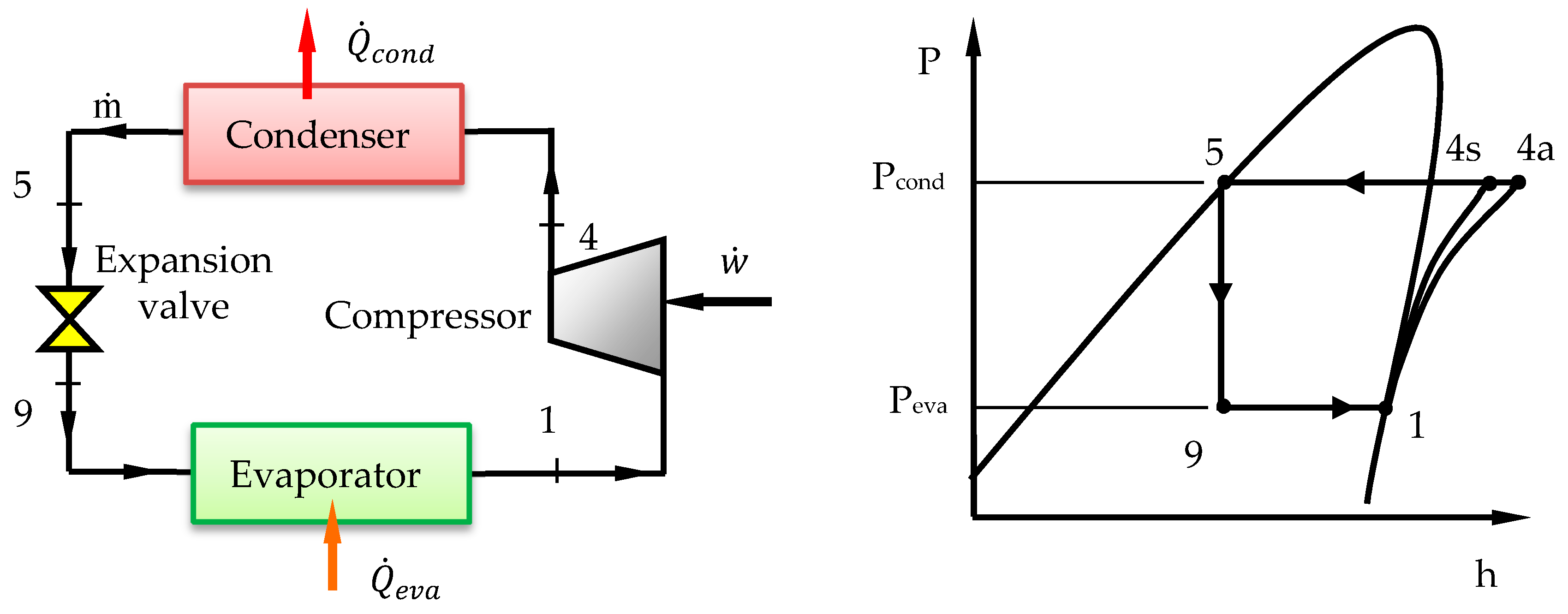
Download scientific diagram | P-h diagram of vapor compression refrigeration cycle Generally, the vapor compression refrigeration system consists of a condenser, an expansion valve, an evaporator, and a compressor. The vapor compression refrigeration cycle consists of four processes: (1-2) ...
Case – 1 The Basics of Refrigeration Cycle P-H Diagram ...
refrigeration cycle 2 . Goals of Lab • To get acquainted with a vapor-compression refrigeration system ... (For the above 3 conditions, use the PH Diagram to determine the enthalpy value)- 7 . Vapor Compression Refrigeration System . Q. e: Cooling load rate (kW) Q. w
P-H Diagram Thermodynamics | HVAC and Refrigeration PE Exam ...
Ph Diagram Refrigeration Cycle. People Also Search. Red 70s Aesthetic. Black 90s Aesthetic. 70s Aesthetic Bedroom. Cute 80s Aesthetic. Vintage Aesthetic 90s Outfits. Punk Guy Aesthetic. Aesthetic 90s Anime Ninja. Aesthetic 90s Glasses. Aesthetic Bed Night. 70s Aesthetic Clothing. Hippie Van Aesthetic.

P-h diagram of the vapour-compression refrigeration cycle ...
Ph diagram for refrigeration cycle Efficiency - Working with the Refrigerant Circuit To measure what is happening the first thing to do is to find the temperatures and pressures at key points in the circuit. Measurement points for Temperature T and Pressure P can be used to define the process. The Vapour Compression Cycle, Practical Circuit and P-h Charts Once the points …

2.3 The basic cycle in a log Ph diagram - SWEP
Fault diagnosis of a vapor compression refrigeration system with hermetic reciprocating compressor based on p-h diagram. International Journal of Refrigeration 45 , 44-54 (2014). Article Google ...

P-h diagrams of: (a) typical refrigeration cycle; and (b ...
evaporator and ejector (cycle 6-7-8-9-10-5-6). The standard VC system is a two-pressure system whereas the EERS is a three-pressure system as can be seen in figure 2. Figure 1. Schematic of EERS Figure 2. p-h diagram of EERS

Category: Using Pressure Enthalpy Diagrams - FUNDAMENTAL ...
Understanding P-H Diagram. Posted in Beginner CRS. Understanding P-H Diagram Posted by By Aung Myat Thu November 28, 2021. ... Understanding of Basic Refrigeration Cycle. Next Post. Understanding of Refrigerants. Quote. Help your country with your knowledge! Share your knowledge with your generation! Online Courses. Home; About Us;

REFRIGERANTS P-H DIAGRAM - Refrigeration - HVAC/R and Solar ...
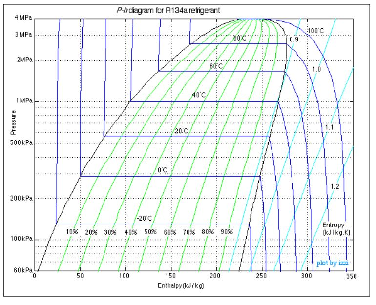
P-h chart is essential to study a vapour compression refrigeration cycle. This chart acts as a tool in understanding the behaviour of a refrigerant. Pressure is plotted on Y-axis (i.e. ordinate axis) and enthalpy (i .e. abscissa axis) as shown in Fig. 3. Fig. 3: Pressure enthalpy chart (P - h Chart)

P-h diagram of vapor compression refrigeration cycle ...
4. A refrigeration system using refrigerant 22 (R-22) is to have a refrigerating capacity of 80 kW. The cycle is a standard vapour compression cycle in which the evaporating temperature is -8°C and the condensing temperature is 42 C. Show the cycle on both T-s and p-h diagrams.

Efficiency - Measuring Refrigeration
Log p-h diagram — In general, a log p-h diagram shows the aggregate state of a substance, depending on pressure and heat. For refrigeration, the diagram is ...
Solved 5. Please refer to the P-h diagram on the following ...
Ph Diagram For Basic Refrigeration Circuit The expansion device is between points 4 and 1. In an ideal cycle, it drops the pressure and temperature of the refrigerant with no heat transfer to the surroundings (adiabatically). Expansion Device 4 2 1 COMPRESSOR EVAPORATOR EXPANSION DEVICE CONDENSER 3

Efficiency - Measuring Refrigeration
Considering the cycle on p-h diagram in Figure 1, the heat absorbed by the refrigerant in the evaporator or refrigerating effect (Q evap , kJ/kg) is calcu- ...

Pressure-Enthalpy diagram for vapour compression cycle ...
ASHRAE HVAC 2001 Fundamentals Handbook.pdf
Case – 1 The Basics of Refrigeration Cycle P-H Diagram ...
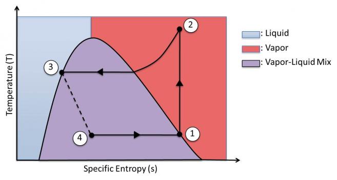
A typical refrigeration cycle is shown in Fig. 4.14. The heat extracted from a low-temperature reservoir converts a two-phase mixture to saturated vapor, which is then compressed adiabatically and (nearly) reversibly. On the T-s diagram, the line from state 1 to state 2 is shown as isentropic.

Pressure-Enthalpy As A Service Tool | ACHR News
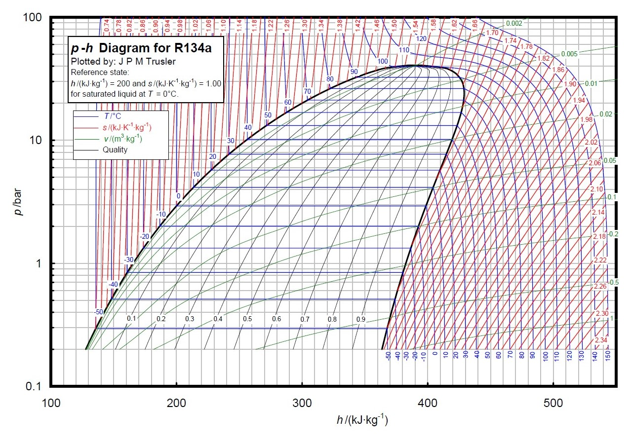
The following sections will show each specific part of the refrigeration cycle on the pressure-enthalpy diagram and it will also highlight the important points and calculations needed. Throughout this explanation the refrigerant R-134a is used as an example. It is recommended that the engineer get a copy of the P-H diagram for R-134a and the other common refrigerants. …
Refrigeration and Heat Pump Systems VaporCompression ...
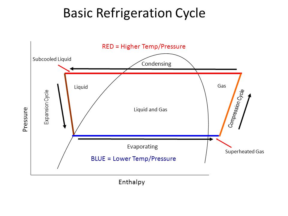
Basic Definition The refrigeration cycle is a thermodynamic cycle to generate refrigerating effect with the use of an evaporator, compressor, condenser & expansion valve.
REFRIGERATION
Figure 2.8 shows the fundamental process that describes the ideal refrigeration cycle. The following are assumed for the fundamental process: No sub-cooling of the liquid or superheating of the gas Ideal compression, i.e. it occurs at constant entropy No pressure drop losses
Processes | Free Full-Text | Performance Analysis and Working ...
Innovative Measurement and Analytical Technology Emerson's tireless pursuit of innovation drives the Rosemount™ portfolio of superior quality measurement and analytical technologies to provide customers with insight across all touch points needed to operate efficiently, safely, and with peace of mind.

Refrigeration - Schematic and a Pressure Enthalpy Chart
the p-h and t-s diagram for the simple vapor compression refrigeration cycle is shown in the figure for vapour entering the compressor is in dry saturation condition the dry and saturated vapour entering the compressor at point 1 that vapour compresses isentropic ally from point 1 to 2 which increases the pressure from evaporator pressure to …
Comparison of Actual and Theoretical Vapor Compression Cycle
nordyne air handler wiring diagram; ph diagram for refrigeration cycle; plot structure diagram pdf; pool filter installation diagram; power window relay wiring diagram; redcat volcano parts diagram; scotts s1642 wiring diagram; seadoo fuel line diagram; spaghetti diagram visio; squash court diagram; the hair diagram; thetford aqua magic v parts ...
Solved A R134a mechanical refrigerator operating with the ...
Helping reporters cover Imperial College London's stories · Our online Media Guide contains the details of over 700 members of Imperial's academic staff who are willing to talk to the media on their areas of expertise

Pressure-enthalpy diagram for a standard vapor-compression ...
Analysis of theoretical cycle: Q 41 = h 1 –h 4 refrigerating effect Q 23 = h 2 –h 3 heat rejection at condenser W = W 12 = h 2 –h 1 work supplied h 1 = h 4 isenthalpic throttling process The P-h diagram of vapor-An ordinary household refrigerator. compression refrigeration cycle.

Problems 4.7 - A Home Refrigerator (updated 3/15/13)
March 13, 2013 -

The Refrigeration Cycle
Each refrigerant has it's own chart which is a graph of the Enthalpy of a refrigerant during various pressures and physical states. Mollier charts are also called Pressure-Enthalpy diagrams. Pressure is shown on the verticle axis, enthalpy is on the horizontal axis.
Pressure-Enthalpy and the Variable Refrigerant Cycle - ppt ...
M. Bahrami ENSC 461 (S 11) Refrigeration Cycle 3 Fig. 5-3: T-s and P-h diagrams for an ideal vapor-compression refrigeration cycle. 1-2: A reversible, adiabatic (isentropic) compression of the refrigerant. The saturated vapor at state 1 is superheated to state 2. wc =h2 − h1
CU Faculty
Discuss temperature-entropy (TS) and pressure-enthalpy (PH) property diagrams for vapor compression refrigeration system.

Refrigeration cycle diagram explained - Refrigeration - HVAC ...
Figure 2.1 shows the principle of a log P/h diagram, and indicates the refrigerant's various thermodynamic states. This diagram can be seen as a map of the refrigerant. The area above and to the left of the saturation line for liquid (A-CP in Figure 2.1) is the area where the refrigerant ...

Draw P-H and T-S diagram when the vapours are superheated at ...
Syllabus: Representation of vapour compression refrigeration cycle on p-v, t- ф and p-h diagrams, use of refrigerant properties tables and p-h (mollior) charts. Theoretical and actual cycle, performance of refrigeration cycle. Effect of change of operation conditions on the working of vapour compression refrigeration plant.

Fault diagnosis of a vapor compression refrigeration system ...
Parker · Products · Aerospace Systems and Technologies · Air Preparation (FRL) and Dryers · Cylinders and Actuators · EMI Shielding · Filters, Separators, Purifiers · Fittings and Quick Couplings · Gas Generators · Hose, Piping, Tubing and T-slot Framing

2.1 The pressure-enthalpy diagram - SWEP
Figure 2.9 The real refrigerant cycle in the log P/h diagram. The overheating is the difference between the temperatures at points 1.1 and 1.2. The sub-cooling is the difference between the temperatures at points 3.1 and 3.2.

Refrigeration cycle diagram explained - Refrigeration - HVAC ...
Refrigeration cycle is the basis of all refrigeration systems. So refrigeration cycle should be known to understand the refrigeration system. Some basic refrigeration cycles are discussed here through different diagrams. 2.2 VAPOUR COMPRESSION CYCLE Vapour compression cycle is an improved type of air refrigeration cycle in which a suitable ...

refrigeration cycle diagram | Refrigeration and air ...
Carbon dioxide was the first gas to be described as a discrete substance. In about 1640, the Flemish chemist Jan Baptist van Helmont observed that when he burned charcoal in a closed vessel, the mass of the resulting ash was much less than that of the original charcoal.
Vapor-compression refrigeration - Wikipedia
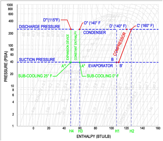
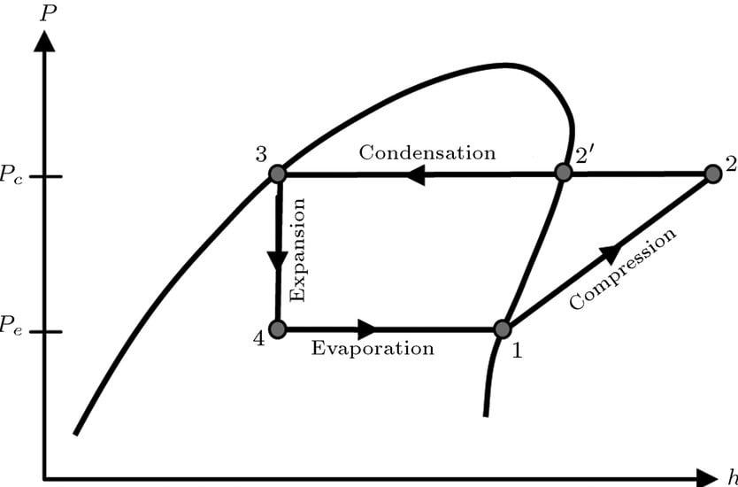
There it is compressed, thus the pressure goes up. This process is represented in p-h diagram as 1-2. This high pressure vapour enters the condenser. There, it looses its latent heat and becomes liquid. (Process 2-3) The liquid refrigerant is stored in a receiver and supplied to the expansion valve, and the cycle continues.

Chapter 4c: First Law - Refrigerators (Updated 3/13/2013)
Learn how to draw a cycle for ideal conditions on a PH chart.Please provide feedback on this module by selecting "Like" or "Dislike". Your feedback and comme...

P H & T S Diagram for Super Heating (GATE) | Refrigeration & Air Conditioning | Thermodynamics |
otg cable wiring diagram; ph diagram for refrigeration cycle; pioneer deh x6700bs wiring diagram; pj bass wiring diagram; plot diagram notes; plot structure diagram pdf; pool filter installation diagram; poulan pro 42cc chainsaw fuel line diagram; poulan pro weedeater fuel line diagram; power window relay wiring diagram

10 CHAPTER Refrigeration Cycles. - ppt video online download
April 18, 2019 - Basic Vapor Compression Refrigeration Cycle and Its components The refrigeration system cannot run without satisfying the second law of thermodynamics (Clausius statement). As the name implies the vapor compression cycle uses a compressor to increase the pressure of the refrigerant or the working ...
Design of Vapor-Compression Refrigeration Cycles
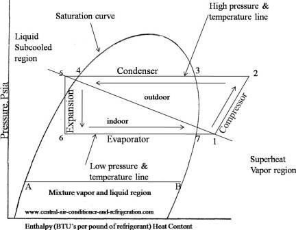
Understanding the basic refrigeration cycle diagram also helps us to find subcooled, superheat and to troubleshoot refrigeration processes much easier. Finding subcooled and superheat is beyond the scope of this discussion. As you can see in the Ph diagram below. Saturation curve this curve represents what state (vapor or liquid) and region (sub-cooled, latent heat, and …

Efficiency - Measuring Refrigeration
The refrigeration cycle of an HVAC system is a critical component governed by the principles of thermodynamics. To understand how it works, first we need to grasp four key concepts. 1. Heat of Vaporization. This refers to the amount of heat required to convert a liquid into a gas. You usually measure it at a liquid's boiling point.
0 Response to "42 ph diagram for refrigeration cycle"
Post a Comment