42 Hot Gas Bypass Diagram
PDF INSTALLATION, OPERATION MAINTENANCE - Climate Solutions, Inc 5 GENERAL DESCRIPTION All AAON CB Series condensing units are factory assembled and wired, including a full charge of R-410A refrigerant for up to 25' of line PDF EVAPORATOR (DX) COIL INSTALLATION, OPERATION ... - CoilCalc 5 - General Diagram, for general piping. 16. If a mist eliminator was purchased with the coil installed, place the mist eliminator into its brackets. Make sure the mesh is aligned with the coil face area (finned area). Figure 3. Hot Gas Bypass Kit Liquid Line Nozzle Equalizer Line Distributor Suction Header Coil Expansion Valve Hot Gas Bypass ...
Odyssey Hot Gas Bypass Kit, R-410A / Installation ... The purpose of a hot gas bypass system is to artificially load the compressor upon a decrease in evaporator load. TheHotGasBypass(HGBP)regulatorvalveautomatically responds to changes in suction pressure.When the refrigerant evaporating pressure is above the bypass valve setting, the valve remains closed.When the cooling
Hot gas bypass diagram
PDF Understanding Hot Gas Bypass - United CoolAir Hot gas bypass is recommended when the load on an evaporator varies and operation of the air conditioning system is desired at lower than design conditions. Additionally, hot gas bypass is used when the evaporator coil is designed for comfort cooling (latent and sensible loads) versus PDF Condensing Units - AAON Figure 16 - Reheat/Hot Gas Bypass Piping Diagram with air handler above condenser ..... 50 Figure 17 - Reheat/Hot Gas Bypass Piping Diagram with air handler below condenser ..... 51 Figure 18 - Reheat/Hot Gas Bypass Piping Diagram with air handler evaporator above condenser and field PDF Hot Gas Defrost - Parker Hannifin the hot gas defrost process. First, when the hot gas valve is sud-denly opened and any condensate in the hot gas line or residual cold liquid in the coil is propelled by the high-pressure vapor. Second, is at the conclusion of defrost, when liquid conden-sate inside the coil is suddenly released to the low side of the system.
Hot gas bypass diagram. Four vital turbomachinery control valves Turbomachinery Controls dedicated to centrifugal and axial compressors use several types of control valves, such as antisurge (recycle) valve, suction throttle valve, hot-gas bypass valve and quench control valve. As the final control element in its control loop, these control valves are vital to implementing good turbomachinery controls. PDF APR CONTROL® FOR R-410A IN SINGLE EVAPORATOR MODE - Rawal 8) External equalizers on sides of APR Control hot gas valve should be connected to the suction line between mixed gas discharge connection from the APR Control and compressor inlet. 9) The injection valve bulb and Hot Gas Bypass valve bulb must be mounted, and insulated, to the suction line between compressor and mixed gas discharge connection ... Category: Using Pressure Enthalpy Diagrams - FUNDAMENTAL ... Hot Gas Bypass (HGBP) and the Pressure Enthalpy Diagram 3/6/2018 8 Comments Hot gas bypass (also called discharge bypass) is a feature in a refrigeration system uses to satisfy the mechanical needs of the system during low load conditions. Hot Gas Bypass (HGBP) and the Pressure Enthalpy Diagram ... Hot Gas Bypass (HGBP) and the Pressure Enthalpy Diagram 3/6/2018 8 Comments Hot gas bypass (also called discharge bypass) is a feature in a refrigeration system uses to satisfy the mechanical needs of the system during low load conditions.
Your Best Hot Gas Bypass Valve Supplier In China-Miracle ... The hot gas bypass valve is also called hot gas solenoid valve. It only needs to add a solenoid to the bypass valve control system. As a reliable refrigeration supplier, Miracle can provide you with multiple types of hot gas bypass, such as Sporlan type bypass valve, Danfoss type bypass valve, Parker type bypass valve, etc. RoofPak Singlezone Roof Mounted Heating and Cooling Units ... O Hot Gas Bypass Valve (optional)* *Supplied on RFS units †Supplied on RCS units. IM-738 Page 7 Refrigeration Piping This section presents the unit refrigeration piping diagrams for the various available configurations. Component numbering ... "Wiring Diagrams" on page 54 for the Legend and compo- PDF Installation Instructions Hot Gas Bypass System Design Manual The hot gas bypass valve monitors the outlet pressure of the evaporator and will begin to modulate open as the load on the unit decreases to the point where the evaporator temperature is at the setpoint of the bypass valve. The bypass valves are factory adjusted to a setting of 68 psig (40°F evaporator temperature). This PDF Trane Engineers Newsletter, volume 32-2 Hot Gas Bypass It's not enough to deliver an HVAC system that meets the unique needs of each application. The owner also deserves a system that is the most reliable and the least costly to operate. In specific cases, adding hot gas bypass to the refrigeration system may be necessary in order to achieve all three goals. But more often than not,
Understanding Hot Gas Bypass | ACHR News Understanding Hot Gas Bypass. Hot gas bypass is recommended when the load on an evaporator varies and operation of the air conditioning system is desired at lower than design conditions. Additionally, hot gas bypass is used when the evaporator coil is designed for comfort cooling (latent and sensible loads) versus precision cooling (all ... PDF CO2 Transcritical Systems Training Manual 042718 shows the PH diagram of R-22, indicating liquid, saturated mixture, and gaseous states. The top of the saturated "dome" is the critical point. Above this point, the refrigerant is not considered liquid or gas, but an undefined fluid. PDF COMPARISON OF REHEAT STRATEGIES FOR CONSTANT ... - Carrier solenoid valve and/or a hot gas bypass circuit often are integrated into the system design. Fig. 6. Pressure/Enthalpy Diagram for Parallel Hot Gas Reheat Cycle Fig. 5. Parallel Hot Gas Reheat Cycle 1' 2' 3' 4' PDF EXD-U02 Universal Driver Module - Emerson Electric Hot gas bypass application diagram keys . ① Temperature Controller . ② Check Valve: It is important to install a check valve just after T-connection as shown. Check valve will not allow return of liquid refrigerant from condenser through electrical control
PDF ThermoSaverTM Hot Gas Defrost System 1. Concept is similar to a "three-pipe" hot gas bypass system yet only uses two pipes (shares the liquid line . and reduces field piping and labour cost). The main . difference is the third shared pipe does not need to be oversized. During the initial hot gas cycle Liquid is fed first, then a mixture, only at the latter part of the
PDF Installation Instructions Hot Gas Bypass System Design Manual The hot gas bypass valve monitors the outlet pressure of the evaporator and will begin to modulate open as the load on the unit decreases to the point where the evaporator temperature is at the setpoint of the bypass valve. The bypass valves are factory adjusted to a setting of 61 psig (35°F evaporator temperature). This
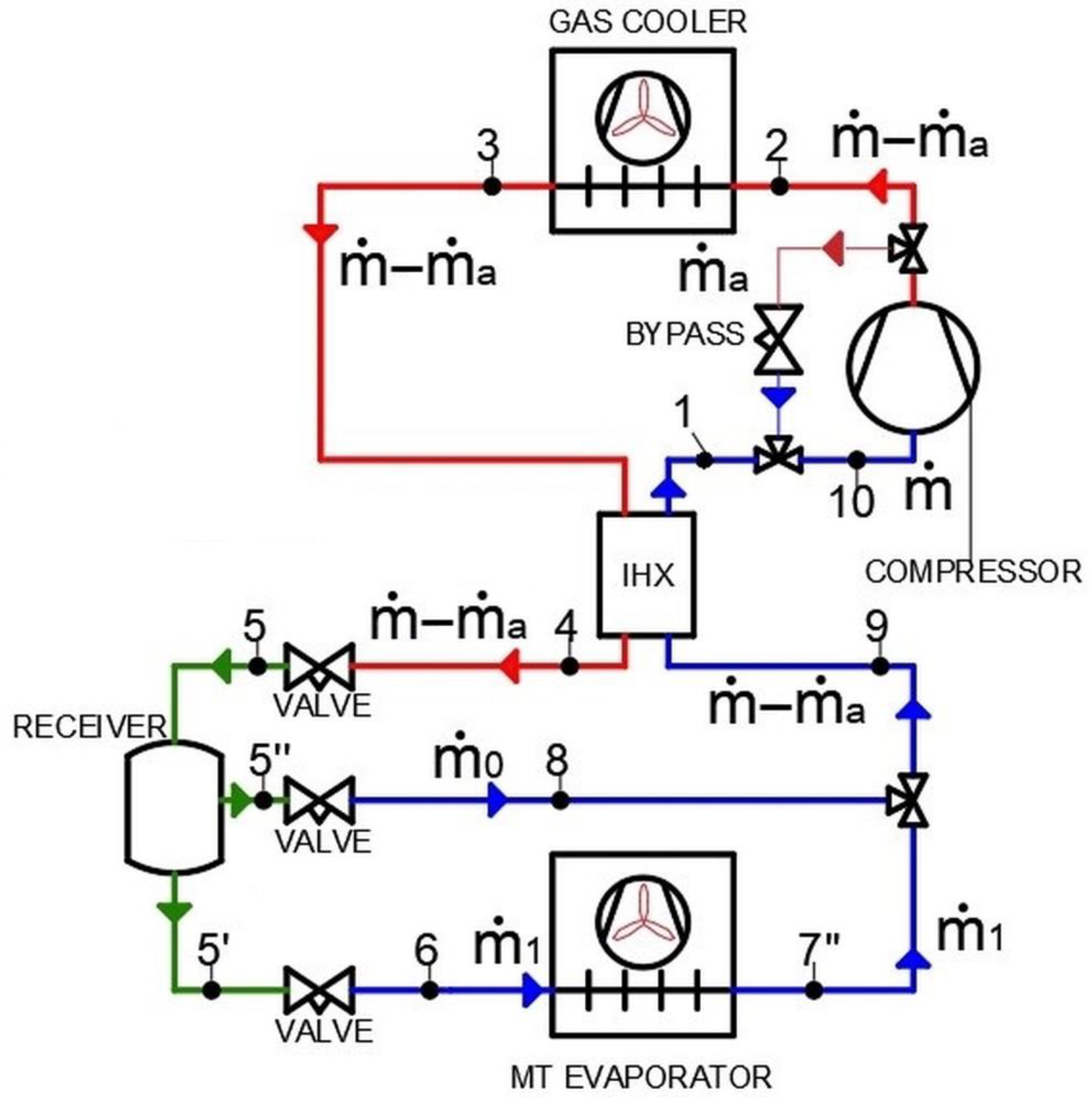
Ini Kontrol Gas Panas Bypass Dalam Sistem Di Mana Suhu Sangat Penting & Kondisi Beban Bervariasi, sangat Beban Rendah
Hot-Gas Reheat, Hot-Gas Bypass, Low Ambient, Modulating ... Over the years I have noticed that there is some confusion as to what each are, what they do and when you need them. This article is written to clear things up. To start, the vapor/compression cycle of typical air conditioning is this: Heat transfers from the space to the evaporator coil and refrigerant in the
Refrigerant Piping Design Guide - Daikin Applied The hot gas bypass line on the circuit runs from the discharge line of the compressor to the liquid line connection at the evaporator. Figure 4: Indoor Chiller with Remote Air-cooled Condenser Air Cooled Condenser Discharge line inverted trap (can be replaced with a check valve) Discharge Line Liquid Line Riser

Paket Pasokan Komprehensif Satu Atap Disesuaikan Sesuai dengan Suhu Inlet Udara Tekan 14Nm 3/Menit dan Desain Titik Embun
PDF MANUAL - Trident Pneumatics cs tid 20 - 250 p & i diagram 4 3.4 schematic diagrams cs tid 300 - 500 p & i diagram instruction manual - coldspell reference : manual version 2 refrigerant line air line electrical line in air adv out air integrated heat exchanger demister pre balance line freon dryer hot gas bypass valve expansion device hp/lp ref. compressor air/air heat ...
Hot Gas Bypass Valve - hvacknowitall.com The Hot Gas Bypass Valve Explained By Gary McCreadie. Hot gas bypass valves are a simple and very effective way to add a false load on an evaporator coil. What is a false load you ask. Well, as we have learned in the past, refrigerant pressures are directly related to the ambient temperature surrounding them.
PDF Modulating Hot Gas eheat - AAON a 3-way solenoid valve to bypass hot refrigerant gas to a reheat coil that is placed after the cooling coil. The 3-way valve is usually controlled by a humidistat in the space that allows the unit to continue the moisture removal process after the dry bulb thermostat has been satisfied. ...
Installation and Maintenance Manual IM 893-1 - Daikin Applied O Hot Gas bypass piping (optional) *† *Supplied on RFS units †Supplied on RCS units. McQuay IM 893-1 7 Introduction ... the wiring diagram legend, which is included in "Wiring Diagrams" on page 55. Figure 7: Control Locations—RPS units R eturn air economizer Filter se ction Supply fan Heat DX
PDF Packaged Rooftop DOAS & Recirculation Unit with Hot Gas Bypass and Modulating Hot Gas Reheat and Subcooling ..... 27 Figure 11: Circuit Diagram for Digital Compressor ..... with Modulating Hot Gas Reheat, and Subcooling 28 Figure 12: Example Energy Recovery Wheel ..... 29 Figure 13: Example Gas Heater Wiring Diagram -
PDF A Modified Through-Flow Wave Rotor Cycle With ... - NASA from the hot gas to the relatively cool rotor wall. The heat transfer leads to apparent reductions in compression efficiency and increases in expansion efficiency. Second, although the interfaces between hot _ / i I Figure 4 Wave diagram of the simplified bypass wave rotor cycle at the design point. and cold gases appear sharp in Figs. 2 and 3 ...
PDF Hot Gas Defrost - Parker Hannifin the hot gas defrost process. First, when the hot gas valve is sud-denly opened and any condensate in the hot gas line or residual cold liquid in the coil is propelled by the high-pressure vapor. Second, is at the conclusion of defrost, when liquid conden-sate inside the coil is suddenly released to the low side of the system.
PDF Condensing Units - AAON Figure 16 - Reheat/Hot Gas Bypass Piping Diagram with air handler above condenser ..... 50 Figure 17 - Reheat/Hot Gas Bypass Piping Diagram with air handler below condenser ..... 51 Figure 18 - Reheat/Hot Gas Bypass Piping Diagram with air handler evaporator above condenser and field
PDF Understanding Hot Gas Bypass - United CoolAir Hot gas bypass is recommended when the load on an evaporator varies and operation of the air conditioning system is desired at lower than design conditions. Additionally, hot gas bypass is used when the evaporator coil is designed for comfort cooling (latent and sensible loads) versus


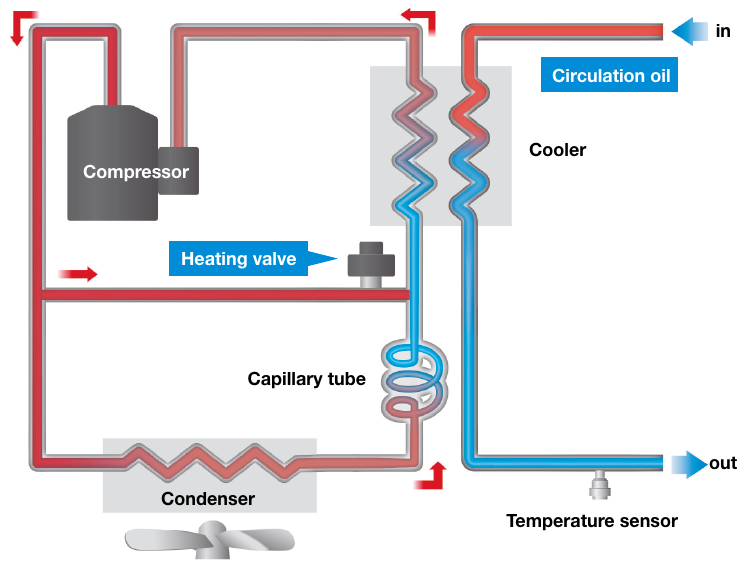
![PDF] Precise Temperature Control of Oil Coolers with Hot-gas ...](https://d3i71xaburhd42.cloudfront.net/fe5e8ed780815a69757202c5213a1d3d020bec4f/3-Figure2-1.png)








0 Response to "42 Hot Gas Bypass Diagram"
Post a Comment