41 ballast resistor wiring diagram
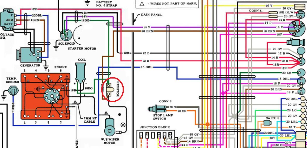
Ignition Coil Ballast Resistor Wiring Diagram. Print the cabling diagram off plus use highlighters to be able to trace the circuit. When you use your finger or even follow the circuit together with your eyes, it is easy to mistrace the circuit. 1 trick that We use is to print the same wiring picture off twice. Update: sadly I think the diagrams are incorrect. They do not show the correct circuit for the fuel pump power. the power for the fuel pump (not the fuel pump relay) goes through the ballast resistor. The resistor is not shown in the wiring diagram and neither is the electronics that bypass the resistor.
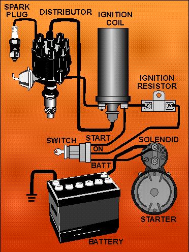
Hi - can anyone explain, or does anyone have a simplified diagram showing how the wiring should run between the ignition coil, ballast resistor and the distributor. Someone previously has taken the ballast resistor out of circuit, and removed all the wiring, so not sure how it should be wired back in. This is for a Silver Shadow II.

Ballast resistor wiring diagram
Ballast Resistor Pertronix Ignitor Wiring Diagram. Wiring the pertronix pertronics distributor 1947 present chevrolet gmc truck message board network no brainer question ballast resistor bmw 2002 and other 02 faq ignitor ii installation instructions pdf manualslib installing vintage mustang forums yes another one for a bos only mopar forum ... Pertronix wiring diagram in addition chevy ballast resistor wiring diagram together with 6 0 engine cooling diagram html furthermore mustang voltage regulator wiring diagram also 92 f engine diagram moreover toyota auris fuse box location moreover club car ignition wiring diagram in addition ford msd ignition wiring diagram together. Find great ... Step 4: Install Ballast Resistor. Set the ballast resistor up to the firewall and screw the clamps in place. Step 5: Connect Wires to Positive. Strip the end of the positive wire from the ignition, and connect it to the positive end of the resistor. From the other terminal on the resistor a wire goes to the positive on the coil.
Ballast resistor wiring diagram. The ballast resistor get's installed on the wire from the ignition switch to the positive side of the ignition coil and it's the wire that is hot when the key is on run not start. the start coil wire should still have 12 volts. One second and I'll pull up the wiring diagram. Ford Ignition Wiring Diagram - wiring diagram plymouth reliant ... I have uploaded picture of a wiring setup found when searching for ballast resistor wiring." That should work just fine. Basically start directly to coil for full 12 volt to start, run goes through the ballast resistor to cut down the voltage to the coil when the engine is running to take the load off of the points. 2020-12-15 · Ignition Coil Ballast Resistor Wiring Diagram from i.pinimg.com. Print the cabling diagram off plus use highlighters to be able to trace the ... When checking voltage at the battery I got 12.43 volts. When I turn the ignition switch on I get 10.55 volts at input wire (disconnected from resistor) to the ballast resistor. With the wires connected to the resistor and the ignition switch on I get 4.75 volts at the positive side of the coil.
Unhook the ballast resistor and find the wire that has power to it coming from the ignition. You should be able to connect your msd directly to that wire and remove the ballast resistor. I think its the blue wire. If there is two blues one may be for crank (ignition 2) and the other for crank and ignition (ignition one). Diagram attached for wiring of points dizzy and coil with ballast resistor. This simple system is easy for even the novice mechanic to wire. A resistor that has the property of increasing in resistance as current flowing through it increases and decreasing in resistance as current decreases. Discussion in 1960 1966 started by ol betsy dec 20 2006. Ford Ballast Resistor Wiring Diagram. Print the wiring diagram off plus use highlighters to trace the signal. When you make use of your finger or perhaps the actual circuit with your eyes, it is easy to mistrace the circuit. 1 trick that We 2 to printing a similar wiring plan off twice. The ballast resistor should be in the circuit. Run the red-green wire from the ignition switch to one side of the ballast resistor. Run another wire from the other ballast terminal to the coil + terminal. Run a bypass wire ( bypassing the pink resistor wire) to the same ballast terminal as the red-green wire.
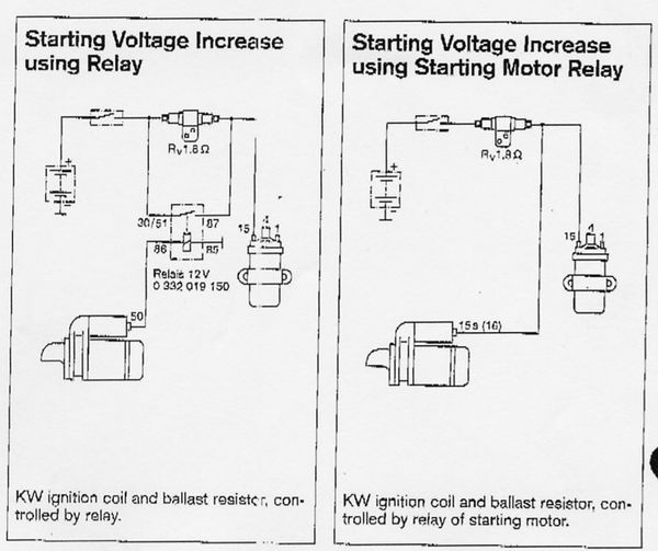
All 1200s used a ballast resistor until the 1990 models. [edit]. Early 1200. NOTE: The 1973 Wiring Diagram doesn't show a resistor, but it definitely has one. This Video explains how the Ballast Resistor Works.For additional How-to Tutorials Visit our Website: http://www.howstuffinmycarworks.com Description: Ignition Coil Ballast Resistor Wiring Diagram with Ignition Coil Ballast Resistor Wiring Diagram, image size 609 X 360 px, and to view image details please click the image. Here is a picture gallery about ignition coil ballast resistor wiring diagram complete with the description of the image, please find the image you need. Eliminates Ballast Resistor, 44KV Output on demand, Plug and Play, one simple wiring modification (Eliminate Ballast Resistor, Kit Included), stock mounting, . TR7 Complete Clutch Kit - 4 Speed Tranmission Mount - Mercedes D, /4, D , tii ZX Accord Alternator for Volkswagen Rabbit, Rabbit Diesel & Rabbit Diesel Pick-Up.
1966 Mustang Coupe wiring - Ford Mustang Forum
I replaced the starter with no positive result then I bypassed the ballast resistor and never had the problem again. After that, I put in an American Auto Wire kit and the ballast resistor has remained for appearances only. I was looking at a wiring schematic and it stated the ballast resistor was required for the instruments to work properly.

Fluorescent Ballast Wiring Diagram Coil | Wiring Diagram ...
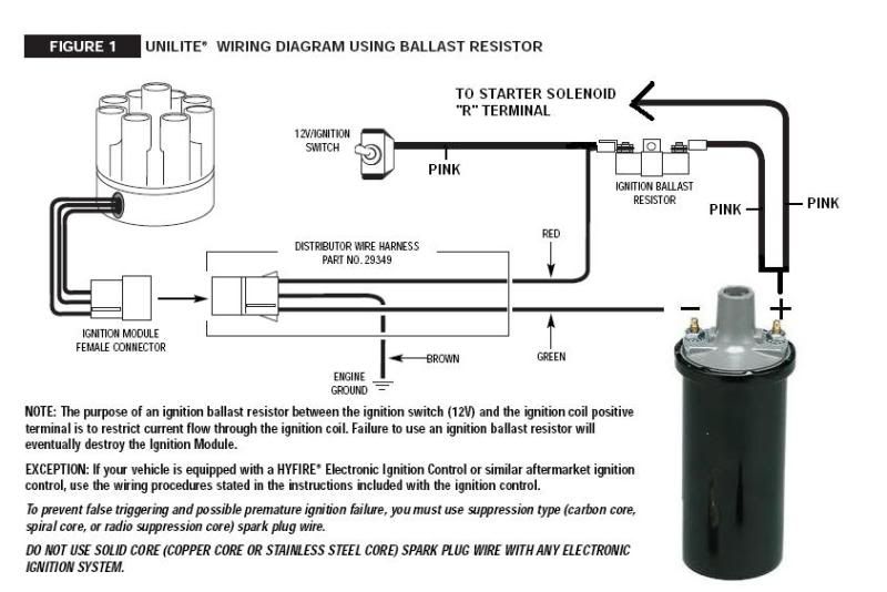
FIGURE 1 UNILITE® WIRING DIAGRAM USING BALLAST RESISTOR NOTE: The purpose of an ignition ballast resistor between the ignition switch (12V) and the ignition coil positive terminal is to restrict current flow through the ignition coil. Failure to use an ignition ballast resistor will eventually destroy the Ignition Module.

Ballast Resistor Wiring Diagram Database
9. Route the blue wire to the ballast resistor. Avoid the exhaust manifolds and sharp edges, follow existing wiring harnesses if possible. 10. Disconnect the wires from both ends of the original ballast resistor. Remove the old ballast resistor and install the new ballast resistor in its place. Do not reconnect the wires. 11.

Ignition Coil Ballast Resistor Wiring Diagram helloo ...
A resistor wire or ballast resistor may or may not be included in the original equipment. The typical automotive ignition system prior to 1974 consisted of a coil and ballast resistor with breaker points to interrupt the current flow when a spark was needed. Diagram Wiring Diagram Ballast Resistor Ignition Coil Full Version Hd Quality …

12v feed for ballast resistor. | For C Bodies Only Classic ...
Step 3. Cut a piece of wire long enough to reach from the other terminal of the ballast resistor to the "Bat", "+" or "B+" terminal of the coil. Strip 1/2 inch of insulation from each end of this wire and crimp a connector onto each end. Connect the wire to the unused terminal of the ballast resistor and to the previously identified terminal of ...

21 Best Ignition Coil Ballast Resistor Wiring Diagram
I can't find the wire for the backup lights on. 1965 convertible. Any suggestions? Do the wires from the neutral Safety Switch go from the switch to under the dash the fuse box? Kevin Bankos — June 1, 2013 3:27 PM . Where is the ballast resistor located for the ignition system in a 65 mustang, 289 2 barrel. This car is burning up points fast.
How To Read A Ballast Wiring Diagram | Cadician's Blog
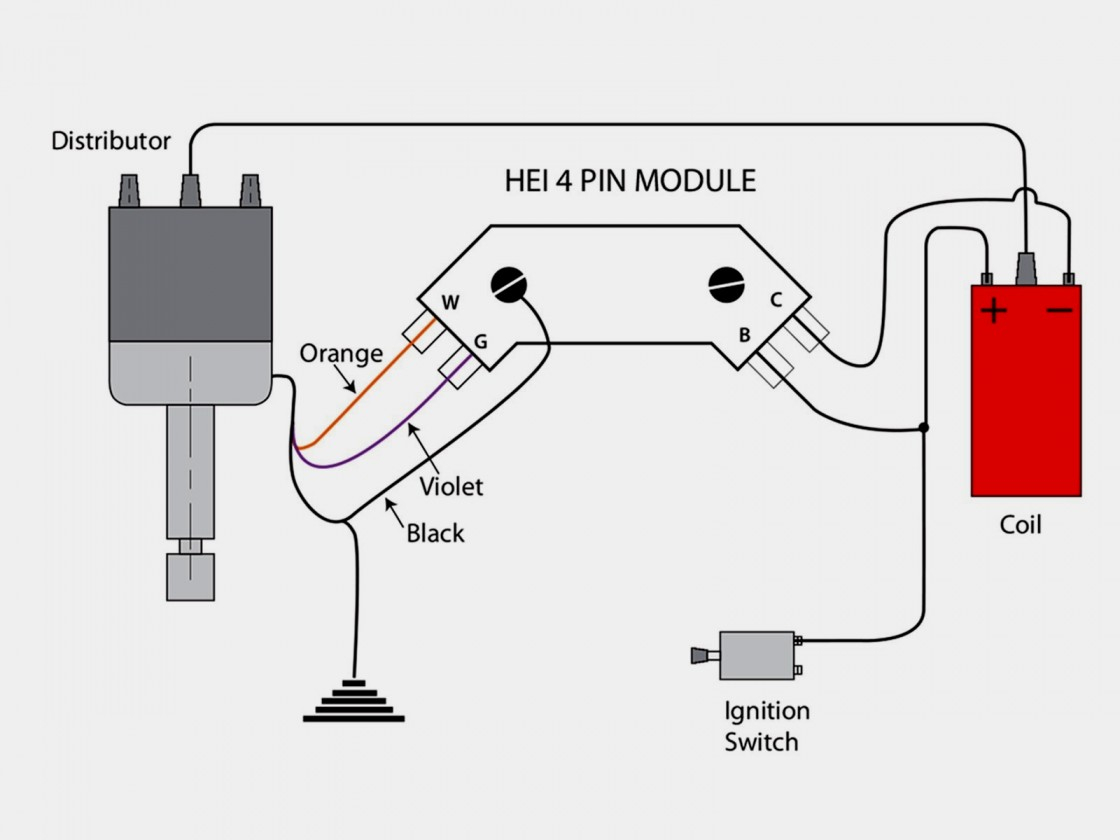
This wiring diagram is for the 1980 and later four pin ignition module. If you have an ignition harness with five wires, just don't connect the dark green wire that would go to pin 3. I Installed a Jacobs computer ignition, and it doesn't require a ballast resistor.

Internal Ballast Resistor Coil
17 Oct 2017 — A ballast resistor is used in a circuit to limit the current and hence prevent it from over current faults. Here, as the current in the circuit ...
Another Ballast Resistor Question - CorvetteForum ...
Only issue I have is that the ballast resistor on my 72 car has 4 connections. There are actually two brown wires twinned together to one post and a green with red tracer on the other post. On the other end of the resistor there is a dark blue wire which has a small black jumper wire with it and goes to the other terminal on that end?
how to wire up ballast resistor - CorvetteForum ...
run through a ballast resistor or wire. Bypass any resistance unit to provide full 12V key ON power to the coil and module. If you set up a battery on a bench and hook up all the wires as shown you can check the spark by toggling the point lead (#5) to ground. You will see a nice hot spark out of the secondary. The circuit is quite simple and works
Igniter and ballast wiring with painless | IH8MUD Forum
Ignition Coil Ballast Resistor Wiring Diagram Led Fluorescent, Led Tubes, Rx7, Fancy Cars. wiringforums. Wiring Forums. 502 followers.
Electronic ignition, Crane/Allison XR700
As a matter of fact, a bad diode trio in a conventional alternator can do the same damage. 2 wiringall.com MALLORY IGNITION-+ COIL FIGURE 1 UNILITE® WIRING DIAGRAM USING BALLAST RESISTOR NOTE: The purpose of an ignition ballast resistor between the ignition switch (12V) and the ignition coil positive terminal is to restrict current flow ...

Ballast Resistor 12 Volt Coil
Ballast Resistor Wiring Diagram. No brainer wiring question ballast resistor bmw 2002 and other 02 faq ignition troubleshooting accuspark diagrams igniter with painless ih8mud forum heavy duty external for coils points electronic systems australian rr forums resistors through the years technical please help h a m b chevy tri five tech wiki coil ...

☑ Ignition Ballast Resistor Diagram
This diagram seems wrong. If I recall. Positive wire off #12 fuse through ballast resistor to coil. Negative wire off coil to ignition. Then just put the ...

Ford Ballast Resistor Wiring Diagram - Wiring Diagram
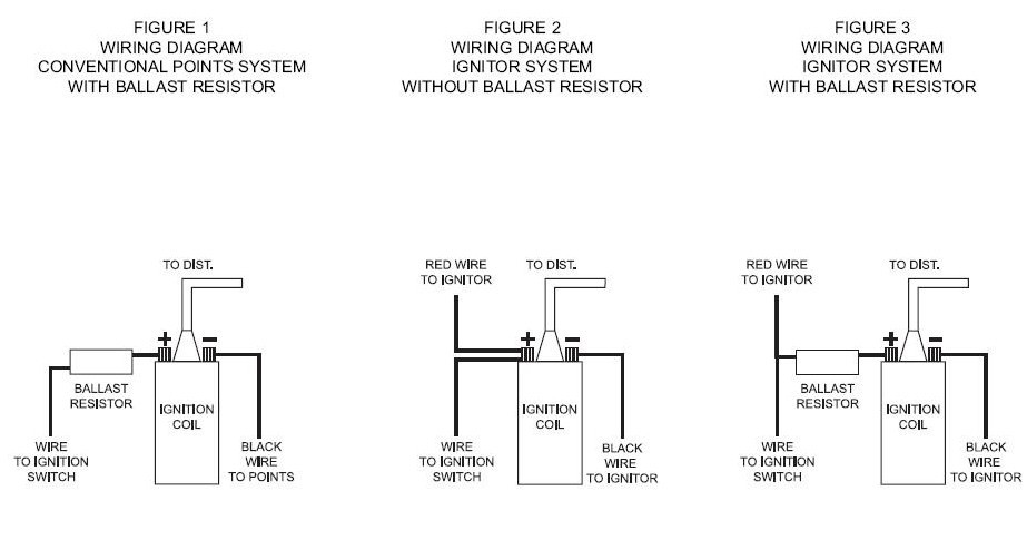
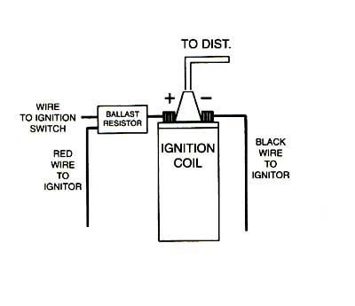
RED WIRE: If you use loom resistance wire, connect to the coil (+) terminal. If you use a ballast resistor, connect to 12 volt side of ballast resistor. GREEN WIRE: Connect to the coil (-) terminal. BROWN WIRE: Connect to engine block ground. Clean away any grease, oil and paint from the mounting surface before the con-nection is made.

Ford Ballast Resistor Wiring Diagram - Wiring Diagram
Make sure that your vehicle is equipped with an ignition ballast resistor (or loom resistance wire) in the wire between the ignition switch and the coil (+) terminal. If you find your vehicle is not equipped with an ignition ballast resistor,install an ACCEL Ignition Ballast Resistor Part No.150001 in series in the wire from the ignition switch.

Ignition Coil Ballast Resistor Wiring Diagram | Fuse Box ...
Disconnect the connections at the ballast resistor. Measure the voltage (or check with a test light) the voltage between the single wire and ground. If there is ...

A nice view of downtown Tampa from Ballast Point over Tampa Bay.
Step 4: Install Ballast Resistor. Set the ballast resistor up to the firewall and screw the clamps in place. Step 5: Connect Wires to Positive. Strip the end of the positive wire from the ignition, and connect it to the positive end of the resistor. From the other terminal on the resistor a wire goes to the positive on the coil.
12V wiring diagram - The CJ2A Page Forums - Page 2
Pertronix wiring diagram in addition chevy ballast resistor wiring diagram together with 6 0 engine cooling diagram html furthermore mustang voltage regulator wiring diagram also 92 f engine diagram moreover toyota auris fuse box location moreover club car ignition wiring diagram in addition ford msd ignition wiring diagram together. Find great ...
Closeup of skeleton pelvic model
Ballast Resistor Pertronix Ignitor Wiring Diagram. Wiring the pertronix pertronics distributor 1947 present chevrolet gmc truck message board network no brainer question ballast resistor bmw 2002 and other 02 faq ignitor ii installation instructions pdf manualslib installing vintage mustang forums yes another one for a bos only mopar forum ...

Accel Ignition Coil Wiring Diagram - Wiring Diagram

What Does A Ignition Ballast Resistor Do
Ford Ballast Resistor Wiring Diagram - Wiring Diagram
Ignition Coil Wiring Diagram - Cadician's Blog

F150 Hid Ballast Wiring Diagram - Wiring Diagram & Schemas
Ford Ballast Resistor Wiring Diagram - Wiring Diagram
Electronic Ign/Hei/Ballast Delete Wiring? | For A Bodies ...
Pagoda SL Group Technical Manual :: Electrical / IgnitionCoil

Advance Ballast Wiring Diagram Resistor - Fuse & Wiring ...

Closeup of skeleton foot model

Universal Hid Ballast Wiring Diagram - Complete Wiring Schemas

Automotive, Ballast Wiring Diagram Professional Single ...
Ballast Resistor - TriFive.com, 1955 Chevy 1956 chevy 1957 ...

☑ Ford Ignition Coil Ballast Resistor

Ignition Coil Ballast Resistor Wiring Diagram Free Picture

Ballast Resistor Circuit
Wiring harness shot - basic hookup to run a 186 motor

Ballast Resistor 12v To 6v

8N ford ballast resistor

Wiring Diagram Ballast Resistor Ignition Coil - Wiring Diagram
62 ballast resistor purpose and readings? - CorvetteForum ...
0 Response to "41 ballast resistor wiring diagram"
Post a Comment