40 vdo marine tachometer wiring diagram
ViewLine 52mm Wiring Diagram (2014) Created On February 27, 2020. Last Updated On February 27, 2020. by Ariel Marquez. Print. Jul 12, 2017 · F17ef Thor Rv Wiring Schematics Digital Resources Thor Wiring Diagram Wiring Wrg 8370 Thor Rv Wiring Schematics F17ef Thor Rv Wiring Schematics Digital Resources
The VDO Programmable Tachometers featured in this VDO's Inductive Sensor is Part # or 02 1.) 2. installation manual are available in three diameters: " gasoline engines or with diesel engines, and can be used with 1. f 9W^YdY_^ 3_Y\ 2QddUbi 0 -. recheck your wiring. you will need to configure it as shown in Diagram D.

Vdo marine tachometer wiring diagram
See page 2 - Setting up the Tachometer. 3. Mount the gauge and secure with the VDO Spin-Lok™ Clamp. (See page 4 for mounting options and instructions) Wiring the Gauge (Illustration A): 1. Route wires from the instrument to: (a) the battery (+) constant power after the fuse box or user supplied in-line fuse - 5 amp fast-blow. Connect the tach using the 10' shielded cable included with the tachometer. Peel approximately 3 to 4 inches of the outside covering and aluminum shielding from the gray cable. This will reveal four individual wires. Three will be insu- lated and one will be uninsulated. Diagram I Wiring to MSD-7AL Ignition 2. Garmin anuncia ganhos recordes no segundo trimestre de 2021. Mercury Smartcraft Speedometer / Tachometer Gauge Kit 79-8m0135648 Marine Boat - 9. 2 nd Bilge pump/auto switch. Smartcraft Wiring Diagram. Så som motorens ydelse, omdrejningstal, hastighed, brændstofflow, temperatur, trim.
Vdo marine tachometer wiring diagram. VDO Tachometer Installation Instructions Subject: Revision: VDO Programmable Tachometer Installation Instructions 10/05/04 B Revision Date: Standards No. 5000041-02 Page 2 of 4 Date Originated: 3.0 Wiring the Tachometer 1. Disconnect vehicle battery ground before performing this wiring. Prepare insulated 1/4"(6.3mm) spade terminals for use. Vdo Marine Tachometer Wiring Diagram - Data Wiring Diagram Schematic - Tachometer Wiring Diagram Wiring Diagram contains several detailed illustrations that present the relationship of varied things. It consists of guidelines and diagrams for various types of wiring techniques as well as other items like lights, home windows, etc. www.marine.vdo.com. 2 ViewLine. 3 Content Content Instrumentation6 Tachometer 6 Synchronizer 8 GPS speed 9 Depth gauges 10 Temperature gauges 11 Pressure gauges 15 Rudder angle 20 Fuel level gauges 21 Trim 25 Ammeter 26 Voltmeter 27 Fresh water and waste water 28 Hour counter 31 Clock 32 shown in Diagram C. You may also mount the tachometer using an optional VDO mounting bracket and nuts. I. Mounting the Tachometer 1. Prepare insulated ¼" spade terminals for use with the tachometer. Make sure all wires are long enough to reach the necessary positive and negative terminals and any wires from the sensor. 2. Connect the wire from ...
-515-010-554. If you have additional questions please contact VDO: Aftermarket Technical Support & Troubleshooting. autotechsupport@vdo.com. Repair & Service for Aftermarket Gauges and Accessories. Connie Heflin. Phone: 540-678-2034. Fax: 540-662-2515. cheflin@vdo.com. 3. Mount the gauge and secure with the VDO Spin-Lok™ Clamp. See page 14-15 for mounting options and instructions. Wiring the Gauge (Illustration D): 1. See page 12-13 for wire harness hookup: b) Tachometer signal source to the purple lead wire. Signal source can be: the Ignition Coil (negative terminal), Alternator W terminal, Inductive , Speedometer. GB. Safety information ... Modifications or manipulations to the VDO product can affect safety. ... according to the electrical wiring diagram.11 pages Vdo Marine Tachometer Wiring Diagram Source: wholefoodsonabudget.com Read wiring diagrams from unfavorable to positive plus redraw the routine as a straight collection. All circuits usually are the same ~ voltage, ground, single component, and changes.
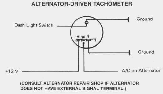
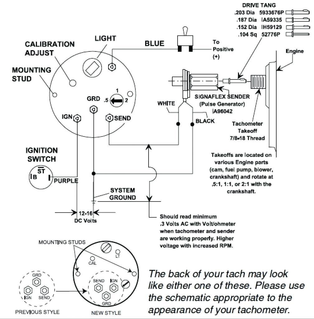
See page 2 - Setting up the Tachometer. 3. Mount the gauge and secure with the VDO Spin-Lok™ ... Connect the harness according to the following wiring.4 pages Diagram E Proper wiring of the VDO Programmable Tachometer with typical ignition systems ˘ˇˆ ˙˘ ˝ˇ ! "˙ Diagram F Fine adjustment of the VDO Tachometer when used with an alternator Compare the VDO Tachometer reading with that of a reference tachometer. Adjust the potentiometer on the back of the tach. When the VDO Tachometer reading Wire the tachometer to the vehicle as shown in Diagram H on Page 4. Please understand that proper wiring must be maintained throughout your vehicle. Smart Actuator II™ Control System Wiring Diagram - Remote Enable Switch . such as Volvo Diesel or any gasoline engine, a mechanical tachometer. The Faria Marine Instrument Bracket Mount Dual Engine. Synchronizer is case of outboard engines). Like a tachometer, the Synchronizer counts "pulses" from. The two most critical parts of the EEC ...
Vdo Viewline Tachometer Wiring Diagram - cleointeriores
Vdo gauges wiring diagrams and boat tach diagram e z go golf cart for boat gauge wiring diagram for tachometer image size 1200 x 1362 px and to view image details please click the image. Attach this con nector to a terminal on the remaining lamp socket which will be referred to as socket b.
tach - Trawler Forum
in Diagram A. 2. Slip the VDO Spin-Lok™ Mounting. Ù. [text continues at #Ë]. Tachometer Wiring: 1. Run wires from the tachometer loca- tion to:.2 pages

Servicing a tide gauge
See Diagram A. Caution: Read these instructions thoroughly before making installation. Do not deviate from assembly or wiring instructions. Always disconnect.

U.S. Marines with Beach and Terminal Operations Company, 1st Landing Support Battalion, 1st Marine Logistics Group, I Marine Expeditionary Force, conduct an external lift of a bulk fuel pump with U.S. Marine Heavy Helicopter Squadron (HMH) 361, Marine Aircraft Group 16, 3rd Marine Aircraft Wing, on Camp Pendleton, California, May 18, 2021.
However, here is a link to a VDO tachometer installation manual: It also has the dip switches. Maybe this will help. VDO used to have a very user-friendly website for installation manuals, but it looks like it's a little more awkward now. But mine has 8 dip switches not just the 3 like in the diagram. Further investigation is needed.

Vdo Gauges Wiring Diagram
VDO Cylinder Head Temperature Gauge Handlebar/Fairing Mount - 2009. VDO Resitive Gauge wiring Instructions - 2009. Veratron Flex Gauge 52mm NMEA2000 12/24v. ViewLine 52mm Wiring Diagram (2014) ViewLine Standard Resistive Gauges 52mm Installation Sheet (2014) Viewline Temperature Gauges 12/24 Volt (2011) Viewline Temperature Gauges 52mm (2008)

VDO Marine - VDO Marine 3-3/8" (85MM) ViewLine Tachometer ...
Wiring Diagram Of Motorcycle Http Bookingritzcarlton Info Wiring Diagram Of Motorcycle Tachometer Boat Wiring Diagram . Vdo spin lok clamp or vdo mounting bracket and nuts 1 5. Vdo volt gauge wiring diagram. Connect the harness according to the following wiring matrix. If using the warning led in the gauge and a vdo sender with warning contact ...

VDO VIEW-LINE MARINE GAUGES IDEAL FOR BOATS & YACHTS
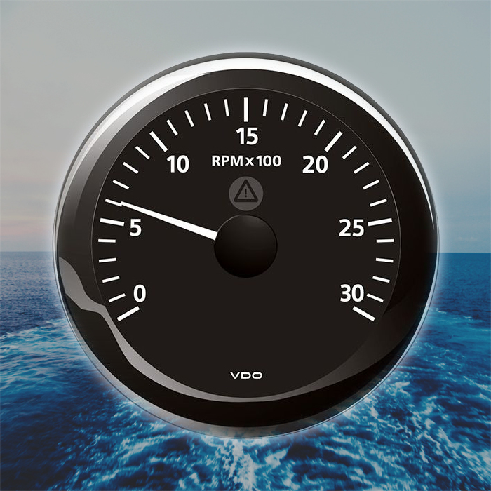
Boat Gauges. Marine gauges are usually console-mounted to allow boaters an overview of the operations at a glance. Each boat gauges indicates an important boating function such as travelling speed, engine temperature, the number of operating hours, the water depth, fuel level, wind speed, water temperature, oil pressure and the amount of electricity being generated.
Yamaha Outboard Analog Tachometer Wiring Diagram - Wiring ...
Description: Vdo Gauges Wiring Diagrams And Boat Tach Diagram E Z Go Golf Cart for Boat Gauge Wiring Diagram For Tachometer, image size 1200 X 1362 px, and to view image details please click the image. Here is a picture gallery about Boat Gauge Wiring Diagram For Tachometer complete with the description of the image, please find the image you need.

Allen Shimada showing king crab caught in Bering Sea on research cruise.
from assembly or wiring diagram. ... Provisions of this warranty shall not apply to a VDO ... For Outboard Engines with Tachometer Pickup off Flywheel.

Vdo Rudder Indicator Wiring Diagram - Wiring Diagram
Tachometer not working mercury outboard

Vdo Marine Gauges Wiring Installation - Wire
Click to get the latest Buzzing content. Take A Sneak Peak At The Movies Coming Out This Week (8/12) Minneapolis-St. Paul Movie Theaters: A Complete Guide

Giant clam
The Deluxe model has 5 gauges. Best prices and worldwide shipping! Sep 07, 2019 · 12 Volt Starter Wiring Diagram Perkins Diesle Wiring Diagram. Find farm equipment salvage for sale in Fastline's large database. 2951 Hours Indicated. 383846 12100 15015 Ei Perkins Engine Marine Instrument Panel Pre Wired Usa Made Package 9.

VDO Tachometer 3000rpm 4000rpm
VDO Marine 2-1/6" (52mm) OceanLink® Pyrometer Gauge (1650° F/900° C) - Black Dial & Bezel. Retail: $59.99. Price: $55.42. View. Availability: Back Order. Item #: 11-76254 -. 2-1/6" (52mm) OceanLink® Pyrometer Gauge (1650° F/900° C) - Black Dial & BezelOceanLink® 52 mm Temperature Gauges are connected directly to any OceanLink® Master ...

Vdo Trim Gauge Wiring Diagram - Complete Wiring Schemas
www.vdo.net.au. 1 CONTENTS Cockpit Vision 4 - 13 Cockpit International 14 - 21 ... Tachometer, digital 36 Marine Tachourmeter 37 Temperature Gauges 37 Pyrometer Gauges 37 Pressure Gauges 38 GPS Speed Gauges 38 Fuel Gauges 39 ... Wiring Kits 87 Conversion Tables

Early VDO Tachometer Guts - Page 2 - Pelican Parts Forums
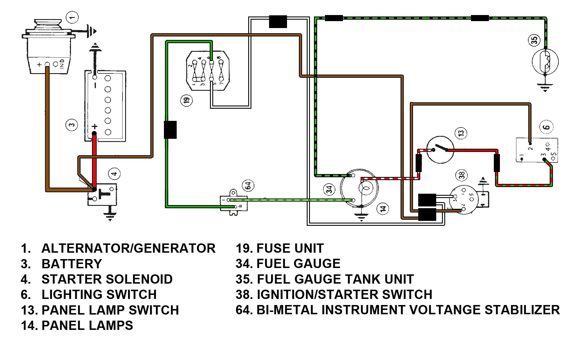
Electrical Wiring: Refer to the wiring diagram, Diagram G. Wire gauges in series from a positive (+) accessory to a source which is not already overloaded with fans, air conditioning, and such. The ground (Œ) wire is also run in series, including the light socket ground. The final ground run, using 14-gauge wire, should be connected to a good ...

Vdo Tach Wiring Electric - Complete Wiring Schemas
4. VDO Spin-Lok™ Clamp or mounting bracket 1 5. Installation Instructions 1 CAUTION: Read these instructions thoroughly before making installation. Do not deviate from assembly or wiring instructions. Always disconnect battery ground before making any electrical connections. If in doubt, please contact your dealer or VDO. s Standard Ground

Vdo Marine Diesel Tachometer Wiring Diagram - Hammasjones
You can (1) look into opening up the tach and replacing the failed plastic gears, (2) add a separate stand alone hour meter or (3) replace the tach unit with a new analog or an Aetna digital. Here is the wiring diagram section of sbmar:

Motorola Tachometer Wiring Diagram - Wiring Diagram
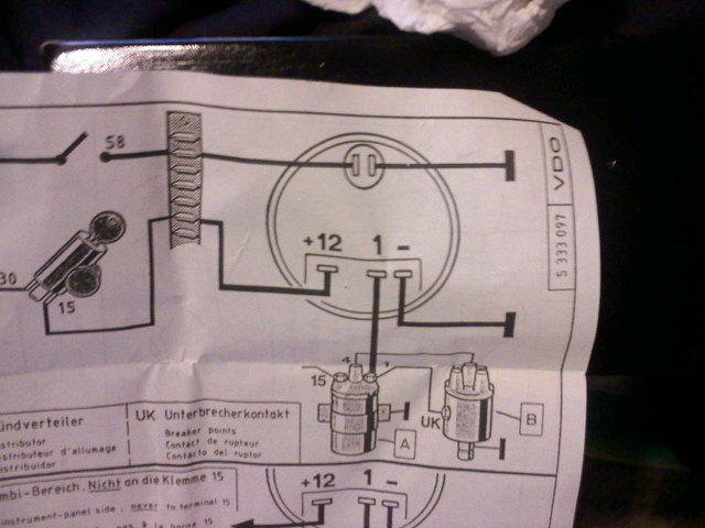
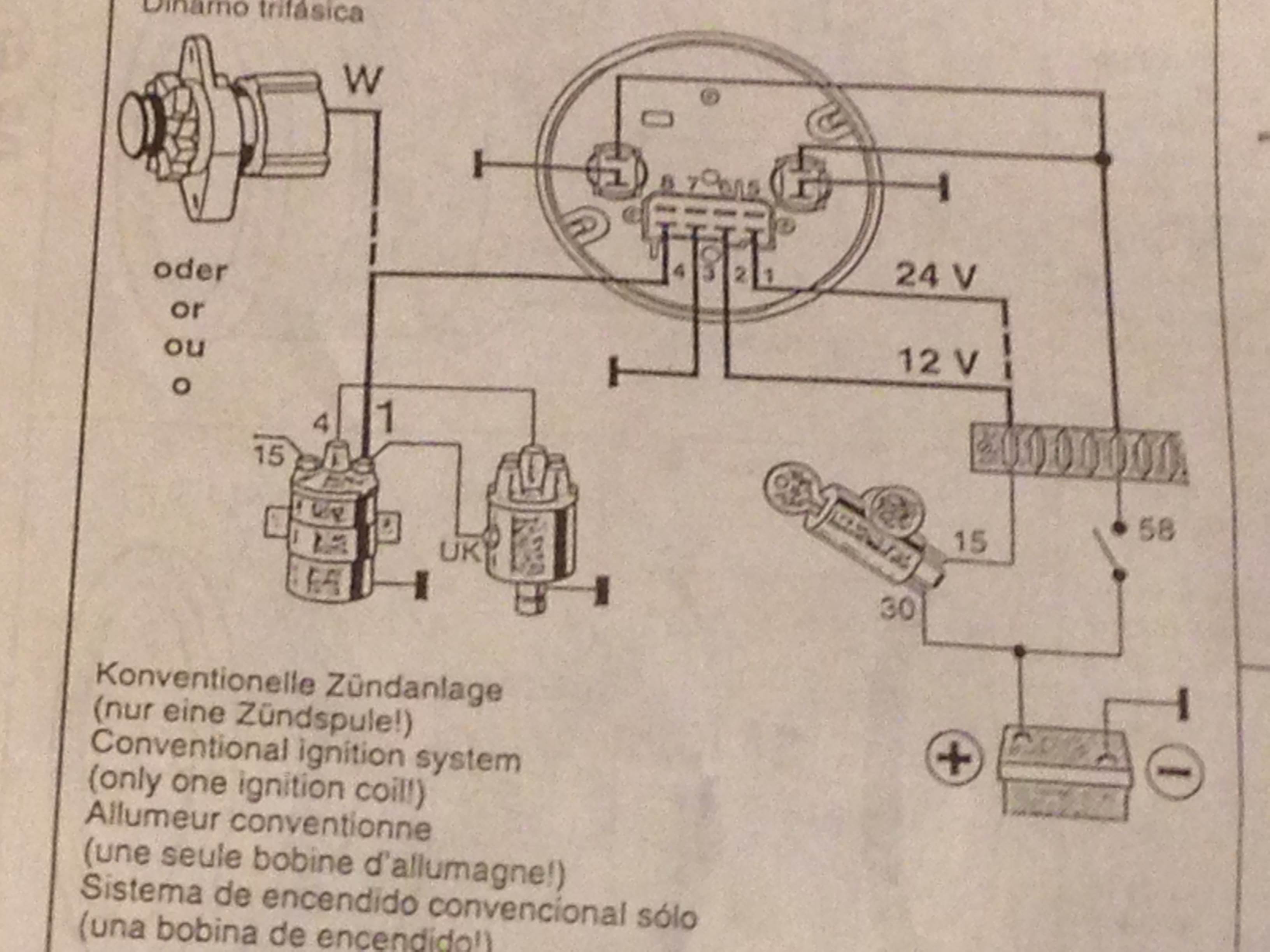
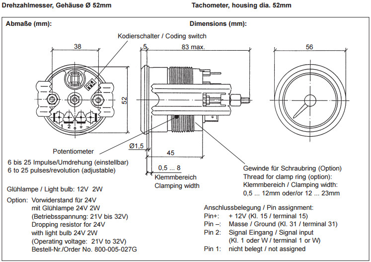
Tachometer, without Display 13 GB 14 Connector set, 8-pin A2C59510850 30 - terminal 30 - steady-state plus 12 V 15 - terminal 15 - connected (ignition) plus 58 - terminal 58 - lighting 31 - terminal 31 - ground Designations in the wiring diagram: 8-pin connection F1 - fuse 5A quick-response C1 - 8-pin MQS connector You must comply with the ...
Vdo Diesel Tachometer Wiring - Complete Wiring Schemas
Vdo Gauges Wiring Diagrams - Page 3 - Wiring Diagram And Schematics vdo marine fuel gauge wiring diagram best of gauge sending. Ford Fusion Relay And Fuse Box Diagram - List Of Schematic ford escape fuse box location just wiring data rh ag skiphire co uk. VDO Spin-Lok™ Clamp or mounting bracket 1 5.
What did you do to your sailing boat today ? | Sailing ...
Troubleshooting Boat Gauges, Instruments And Meters. Make sure rear of instrument has sufficient clearance from existing equipment and wiring. C. Wire gauge according to diagram. VDO Wiring Diagrams - Diagram will open in a new window. Wholesale Marine and Building Supplies. Fuel. Voltmeter. Oil Pressure - no light. Oil Pressure - w/ warning light.

Vdo Marine Fuel Gauge Wiring Diagram
A Vdo Marine Tachometer Wiring Diagram can be really a compacted conventional pictorial representation of a electric circuit. It shows that the components of the circuit because simplified shapes, and also the power and signal connections in between the apparatus. vdo tach wiring instructions - wiring library •, size. Wire & Wiring Harnesses.
![[MV_2140] Vdo Marine Hour Meter Wiring Diagram Download ...](https://static-assets.imageservice.cloud/139152/vdo-wiring-diagrams-wiring-diagram.jpg)
[MV_2140] Vdo Marine Hour Meter Wiring Diagram Download ...
Feb 14, 2011 · VDO makes nice gauges for sure. Boat part number 8502691 is a new ignition and switch dash mount panel for a 2016, 280 Sundancer Sea Ray Boat, part number 2199875 . The Sea Ray SDX 250 OB is a deckboat with a wide topside flare forward that has superior social space for up to 14 people.

Vdo Marine Tachometer Wiring Diagram
Description: Vdo Gauges Wiring Diagrams And Boat Tach Diagram E Z Go Golf Cart for Boat Gauge Wiring Diagram For Tachometer, image size X px, and to view image details please click the image. Here is a picture gallery about Boat Gauge Wiring Diagram For Tachometer complete with the description of the image, please find the image you need. Vdo ...
VDO Viewline Tachometer Marine Boat Gauge 3000 RPM 85mm 3 ...
Vdo Marine Tachometer Wiring Diagram - Data Wiring Diagram Schematic - Tachometer Wiring Diagram Wiring Diagram contains several detailed illustrations that present the relationship of varied things. It consists of guidelines and diagrams for various types of wiring techniques as well as other items like lights, home windows, etc.

VDO Gauges wiring guide - Dragon
Garmin anuncia ganhos recordes no segundo trimestre de 2021. Mercury Smartcraft Speedometer / Tachometer Gauge Kit 79-8m0135648 Marine Boat - 9. 2 nd Bilge pump/auto switch. Smartcraft Wiring Diagram. Så som motorens ydelse, omdrejningstal, hastighed, brændstofflow, temperatur, trim.

Mother manatee and calf swimming out of the inlet.
Connect the tach using the 10' shielded cable included with the tachometer. Peel approximately 3 to 4 inches of the outside covering and aluminum shielding from the gray cable. This will reveal four individual wires. Three will be insu- lated and one will be uninsulated. Diagram I Wiring to MSD-7AL Ignition 2.

Vdo Marine Diesel Tachometer Wiring Diagram - Hammasjones
See page 2 - Setting up the Tachometer. 3. Mount the gauge and secure with the VDO Spin-Lok™ Clamp. (See page 4 for mounting options and instructions) Wiring the Gauge (Illustration A): 1. Route wires from the instrument to: (a) the battery (+) constant power after the fuse box or user supplied in-line fuse - 5 amp fast-blow.
![[AS_8939] Vdo Tachometer Wiring Instructions Schematic Wiring](https://static-resources.imageservice.cloud/962837/vdo-electronic-speedometer-wiring-diagram-basic-electronics-wiring.jpg)
[AS_8939] Vdo Tachometer Wiring Instructions Schematic Wiring

6 Gauge Wire Marine Simple Vdo Cockpit Fuel Gauge Wiring ...

The dredge in action. Fish, scallops, crabs, starfish, and trash are sorted into baskets and buckets, then taken into the wet lab where they are measured and weighed.
Early Twentieth Century Vessels 1900-1939: Plotting the position of the Coast and Geodetic Survey Ship PATHFINDER while operating in Alaskan waters.
VDO Rev-Counter Tachometer Gauge 6000 RPM 52mm 2" 12V 333 ...

Vdo Marine Fuel Gauge Wiring Diagram
Sea Pro Wiring Diagram Vdo Fuel Gauge | schematic and ...

One Tree Reef. Sponge.

Vdo Marine Tachometer Wiring Diagram

Vdo Marine Gauges Wiring Installation - Wire

Mother manatee and calf swimming out of the inlet.
Killer whale dorsal fin

Pin on Electrical system
0 Response to "40 vdo marine tachometer wiring diagram"
Post a Comment