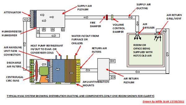
40 furnace air flow diagram
How to figure the air flow through a Gas Furnace using the SuperCool Slide Rule. www.supercoolsliderule.com Wire furnace according to the Field Wiring Diagram shown. There are a lot of choices when it comes to installing a furnace, and one of the choices has to do with how the warm air will flow from your. A concise, illustrated explanation of how upflow, downflow, and horizontal forced- air furnaces work. Forced-air Furnace Duct Work Diagram.
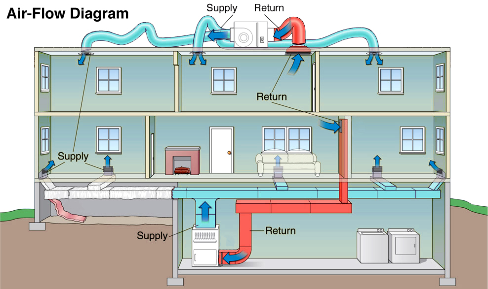
Red, here's a diagram that shows airflow in a furnace: Share. Improve this answer. Follow this answer to receive notifications. edited Mar 11 '14 at 11:57. Tester101. 127k 74.
Furnace air flow diagram
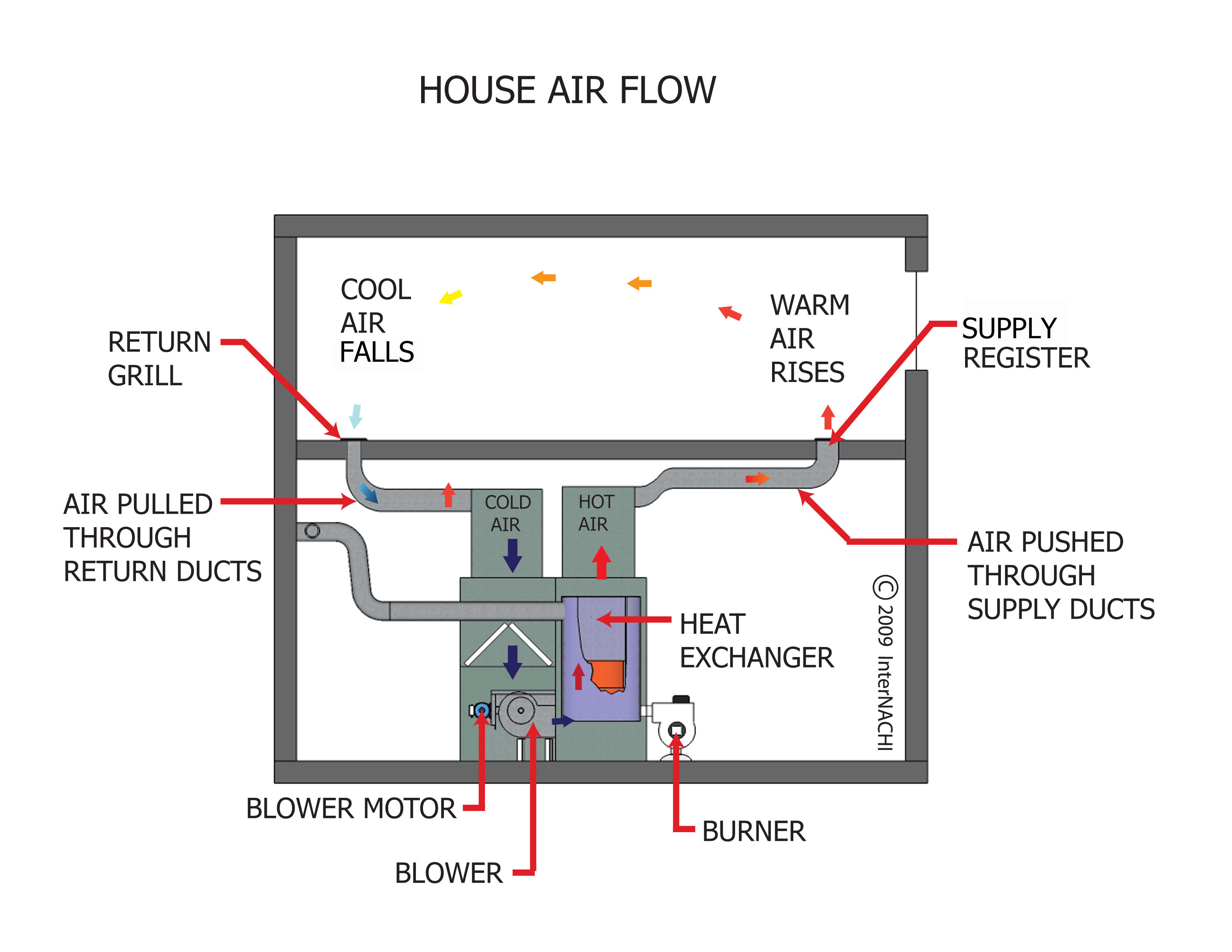
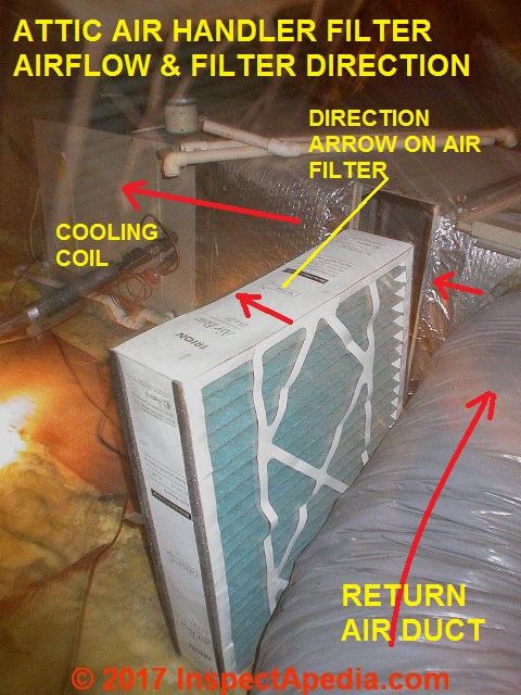
You’re welcome! Which Way Does Furnace Air Flow? Forced air furnaces recirculate air through a home: pushing air (cool or heated) in, and pulling spent air back in for another cycle. So, air flows from your ducts, through the filter, and into the furnace. What’s The Right Furnace Filter Direction? Dec 05, 2014 · Furnace Troubleshooting Flowchart. This gas furnace troubleshooting flowchart should help you troubleshoot and see what is wrong with your furnace. Just follow the steps. You will need a voltmeter for testing. The picture below is pretty small, especially if you do not have any zooming capabilities with your computer. Furnace Fried at 30% Full Load . To Atmosphere . Steam/Air Mixture . Effluent sent to combustion chamber (i.e. Firebox) Notes: 1. Max decoking firing time for all six furnaces is 864 hours per year @ 30% normal load (119 MMBtu/hr) 2. Decoking operations will occur a maximum of 12 events per year per furnace.
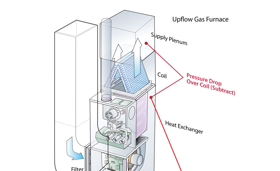
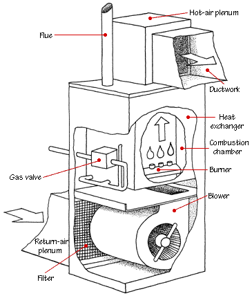
Furnace air flow diagram. of the air flow to dislodge it, the particle will stick to the fiber. Interception is enhanced when the size of the fiber is closest to the size of the particle (see Figure 6 on the next page). 3 A i r f l o w, c f m P r e s s u r e d r o p, i n . w. g . Time Figure 4. Pressure drop graph The term air flow configuration describes the physical orientation of a furnace relative to the direction in which heated air leaves the furnace and enters the ductwork. The most common terms used to describe the air flow configuration are: upflow, downflow, and horizontal. Upflow Furnaces This illustrated guide diagrams the various parts of a gas furnace and explains how they all work together. A gas forced-air heating system goes into action when the thermostat tells it that the room temperature has dropped below a preset comfort level. AIR FLOW AIR FLOW AIR FLOW NOTE - This furnace is designed for a minimum continuous return air temperature of 60°F (16°C) or an intermittent op eration down to 55°F (13°C) dry bulb for cases where a night setback thermostat is used. Return air temperature must not exceed 85°F (29°C) dry bulb. The furnace may be installed in alcoves ...
Main Parts of a Furnace (with Diagram) ... The burners are where gas and air are combined to generate flame, therefore becoming the heat source of your gas furnace. They heat up the air inside of the heat exchanger. Fuel is sent to these burners, which are ignited by the hot surface igniter or the pilot light, sending heat to the heat exchanger ... Furnace Fried at 30% Full Load . To Atmosphere . Steam/Air Mixture . Effluent sent to combustion chamber (i.e. Firebox) Notes: 1. Max decoking firing time for all six furnaces is 864 hours per year @ 30% normal load (119 MMBtu/hr) 2. Decoking operations will occur a maximum of 12 events per year per furnace. Dec 05, 2014 · Furnace Troubleshooting Flowchart. This gas furnace troubleshooting flowchart should help you troubleshoot and see what is wrong with your furnace. Just follow the steps. You will need a voltmeter for testing. The picture below is pretty small, especially if you do not have any zooming capabilities with your computer. You’re welcome! Which Way Does Furnace Air Flow? Forced air furnaces recirculate air through a home: pushing air (cool or heated) in, and pulling spent air back in for another cycle. So, air flows from your ducts, through the filter, and into the furnace. What’s The Right Furnace Filter Direction?
HVAC - Upgrades to Improve Efficiency
HVAC Duct Air Flow - Inspection Gallery - InterNACHI®
Air Conditioners: Air Filters for Heating and Air ...

Split Air Conditioner Wiring Diagram | Refrigeration and ...
Duct Dynasty: Four Essential Static Pressure Readings for ...

Furnace Air Flow Direction Diagram 2021 - WensBurg.com
Furnace Blower Wheel Diameter Question - HVAC - DIY ...

InterNACHI Inspection Graphics Library: HVAC » Heating ...

The flow sheet of the I concept for heating and air ...

Upflow:

Basics of HVAC System : Pharmaceutical Guidelines

Best Central Air Conditioning Buying Guide - Consumer Reports
Residential Air Flow Balancing: Why It Matters in Creating ...

Gas Furnace Fundamentals

Image from page 343 of "Heating and ventilating buildings : a manual for heating engineers and architects" (1910)

A nice gentle sky for use as an element or background.

Sir Isaac Lowthian Bell Bt F.R.S. (1816-1904) by Henry Tanworth Wells - Town Hall, Middlesbrough

Image from page 636 of "Electric railway journal" (1908)

Which direction should the furnace air filter arrow point ...

Pin on Good To Know
Royal Plus Home & Commercial Services | Ocean City MD ...

WRH Walk in Ovens, Horizontal Air Flow | Sepor, Inc

Sky

Replacement Furnaces
rear heat ducting - Page 2 - Rennlist - Porsche Discussion ...

Image from page 298 of "Mastering power production ; the industrial, economic and social problems involved and their solution" (1921)

Are You Having Furnace Problems?

Sir Isaac Lowthian Bell Bt F.R.S. (1816-1904)

hvac - Which way does the air flow through my furnace ...

Sir Isaac Lowthian Bell Bt F.R.S. (1816-1904) by Henry Tanworth Wells
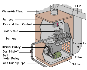
How a Gas Furnace Works
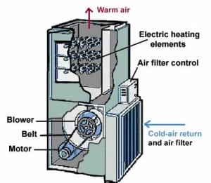
How an Electric Furnace Works

Mid efficiency gas furnace (C) Carson Dunlop Associates ...

Evap Blending / ALWAYS HEAT / AC Lines COLD - Honda Civic ...

Image result for ahu layout in 2021 | Refrigeration and ...
System and Wiring - Classic Comfort Heating & Supply
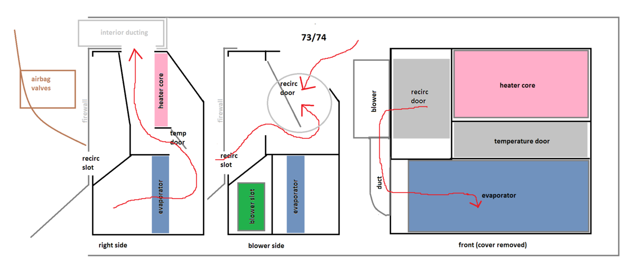
hvac air conditioner ac heater evaporator air flow diagrams
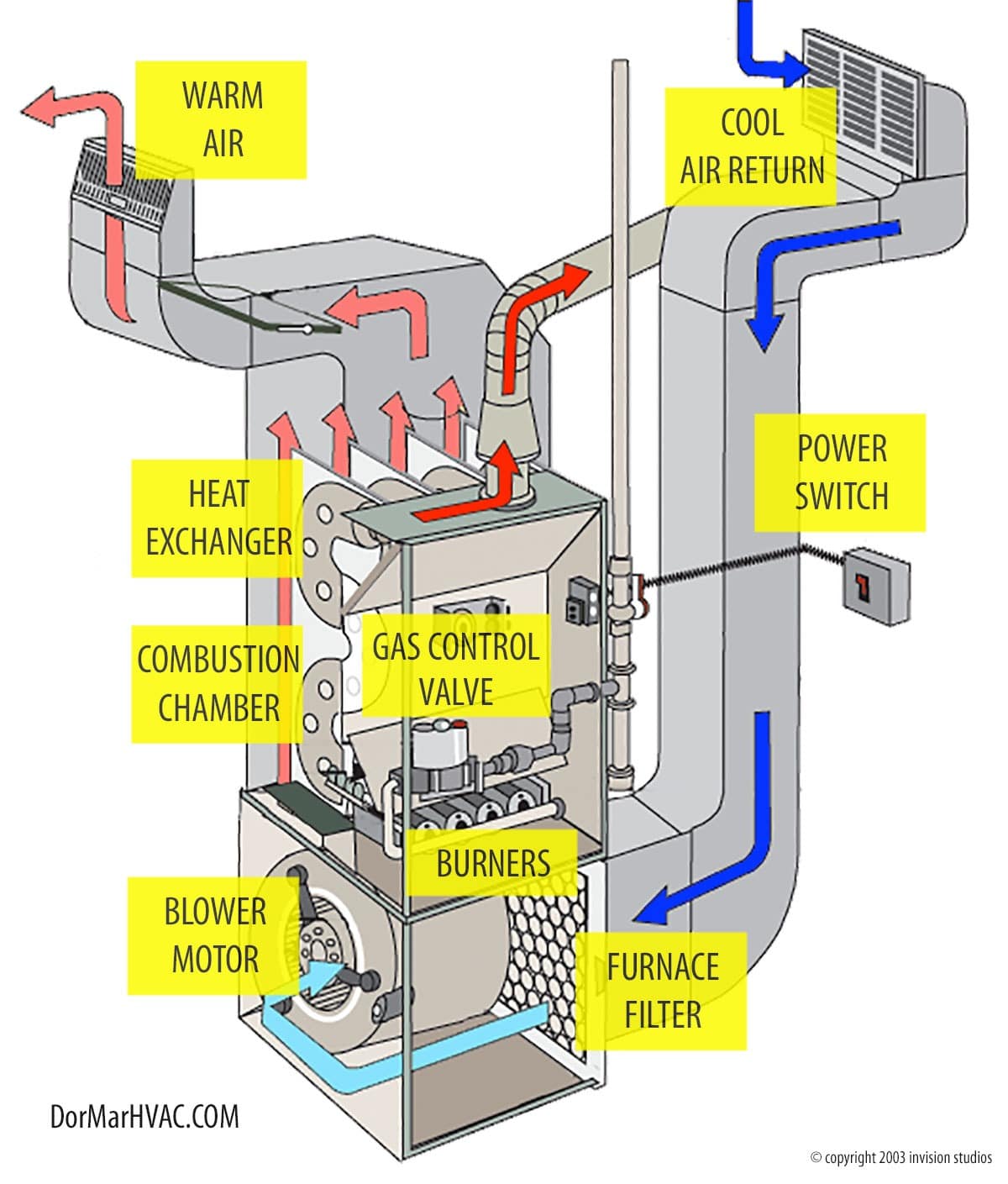
How Does A Furnace Work? - Dor-Mar Heating & Air Conditioning

Sequence of Operation for a Gas-Fired Furnace - Doug's ...

Air Conditioner Air Flow Direction Diagram : furnace ...
0 Response to "40 furnace air flow diagram"
Post a Comment