40 consider the circuit diagram in the figure
I have this circuit: [https://imgur.com/a/aDUYgxN](https://imgur.com/a/aDUYgxN) and I don't understand the part with the potentiometer (top left). I want it to draw the circuit in Proteus, but I don't know how to connect that part. So far I have this in Proteus: [https://imgur.com/a/SLieU9I](https://imgur.com/a/SLieU9I) What do I do now with RV2? How do I connect it? Also, while I'm at it, does someone know the difference between those 2 types of potentiometers in Proteus (RV2 and RV3)? ... I got my first ne555 timer and I’m reading the datasheet. http://www.ti.com/lit/ds/symlink/na555.pdf I’m looking at the setup for the mono stable circuit, Figure 9, page 10. The surrounding text reference Q1, capacitor C and capacitor CL. Maybe I can guess where they should be based on context, but I feel like I’m missing something. How do I determine C and CL from this schematic?
Phasor Diagrams Explained. Here are a number of highest rated Phasor Diagrams Explained pictures on internet. We identified it from well-behaved source. Its submitted by paperwork in the best field. We take this kind of Phasor Diagrams Explained graphic could possibly be the most trending subject gone we allowance it in google lead or facebook.
Consider the circuit diagram in the figure
Here is the network circuit diagram: https://pasteboard.co/HZZGhia.jpg I have both connection, from same ISP. One is 8mbps plan where I get only 1Mbps upload speed. Other Connection which I recently got is 10Mbps plan where I get 1:1 UL/DL speeds. I want to know the reason between difference of upload speeds between two connection. Except Microsoft Visio Question; Figure shows the circuit diagram of a square-law modulator. The signal applied to the non linear devices is relatively weak, such that it can be represented by a square law: v2 (t) = a1v1 (t) + a2v21 (t), where a1 and a2 are constant, and v1 (t) is the input voltage and v2 (t) is the output voltage.
Consider the circuit diagram in the figure. Funk is a music genre that originated in African American communities in the mid-1960s when musicians created a rhythmic, danceable new form of music through a mixture of soul, jazz, and rhythm and blues (R&B). It de-emphasizes melody and chord progressions and focuses on a strong rhythmic groove of a bassline played by an electric bassist and a drum part played by a percussionist, often at ... Machine learning (ML) is the study of computer algorithms that can improve automatically through experience and by the use of data. It is seen as a part of artificial intelligence.Machine learning algorithms build a model based on sample data, known as training data, in order to make predictions or decisions without being explicitly programmed to do so. Christianity is an Abrahamic, monotheistic religion based on the life and teachings of Jesus of Nazareth.It is the world's largest religion, with about 2.5 billion followers. Its adherents, known as Christians, make up a majority of the population in 157 countries and territories, and believe that Jesus is the Son of God, whose coming as the messiah was prophesied in the Hebrew Bible (called ... Hello, i have to draw the diagram of LM331 with a circuit and was looking for a nice online circuit diagram drawer. What is your suggestions?
Question; Figure shows the circuit diagram of a square-law modulator. The signal applied to the non linear devices is relatively weak, such that it can be represented by a square law: v2 (t) = a1v1 (t) + a2v21 (t), where a1 and a2 are constant, and v1 (t) is the input voltage and v2 (t) is the output voltage. Except Microsoft Visio Here is the network circuit diagram: https://pasteboard.co/HZZGhia.jpg I have both connection, from same ISP. One is 8mbps plan where I get only 1Mbps upload speed. Other Connection which I recently got is 10Mbps plan where I get 1:1 UL/DL speeds. I want to know the reason between difference of upload speeds between two connection.
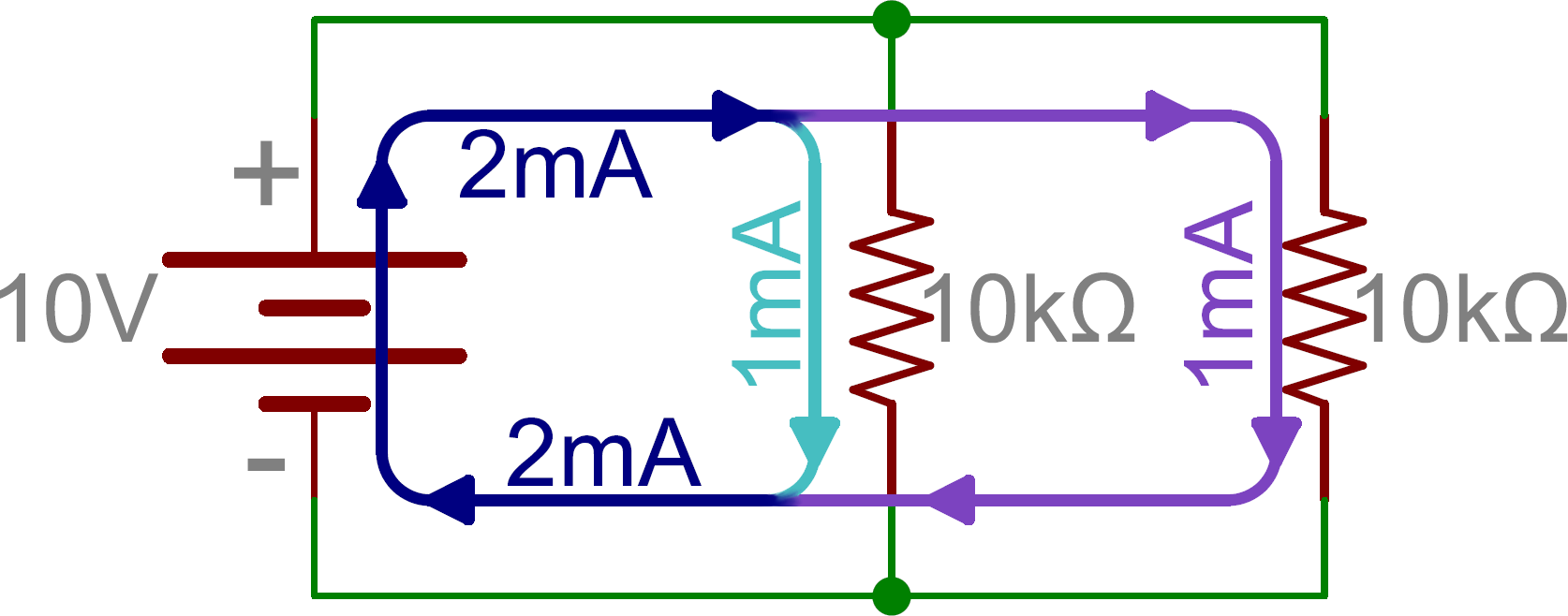
Find the voltmeter reading in a circuit | Physics Forums

The Stone Man

Image from page 368 of "A text-book of electrical engineering;" (1920)
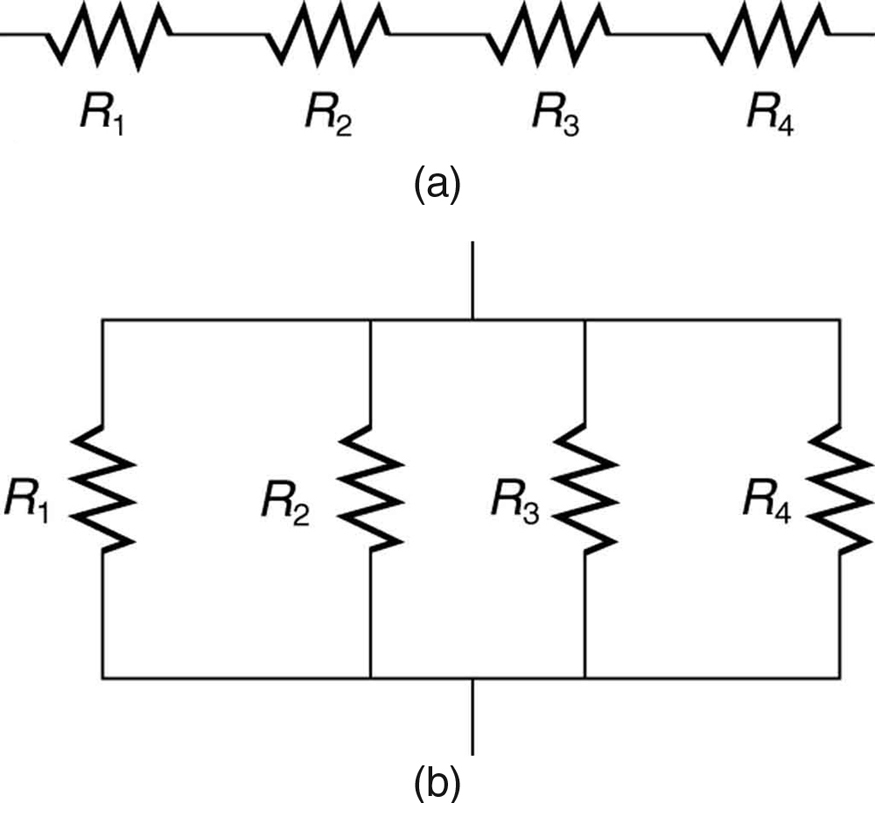
21.1 Resistors in Series and Parallel - BCIT Physics 0312 ...

Image from page 317 of "United States Court of Appeals For the Ninth Circuit" (1902)
Circuit Diagrams - DIYODE Magazine
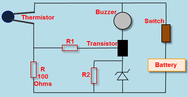
Heat Detector Circuit and Working - Electronic Circuits
Series and Parallel Circuits - learn.sparkfun.com
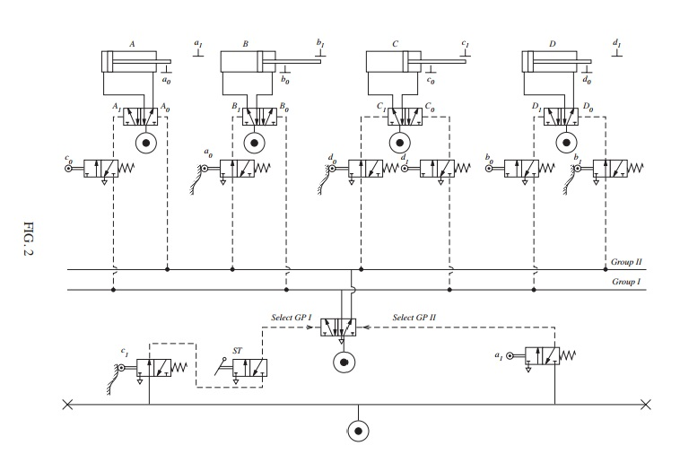
Solved: FIGURE 2 Shows A Pneumatic Circuit In Which Four A ...

SCEPTRE: Simulation of Nonlinear Electrical Circuits ...

Image from page 630 of "An elementary book on electricity and magnetism and their applications" (1919)
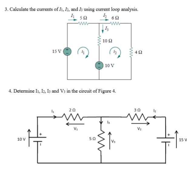
Solved: Calculate The Currents Of I1,I2 And I3s Using Curr ...

To Determine Resistance of a Galvanometer By Half ...

Image from page 341 of "American journal of physiology" (1898)
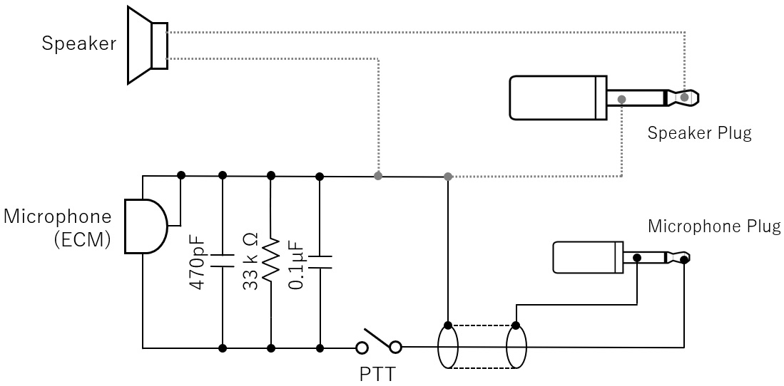
Short Break / The mystery of controlling the microphone ...

Xb Falcon Wiring Diagram

Mr Toogood Physics - EMF and internal resistance
The given figure represents an arrangement of ...

To Convert The Given Galvanometer (of Known Resistance And ...

in the circuit diagram , suppose the resistors R1, R2, and ...
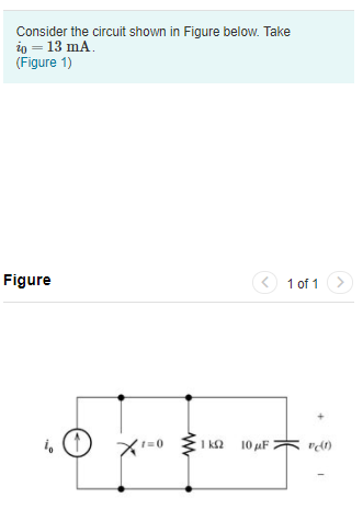
Solved: Consider The Circuit Shown In Figure Below. Take ...

How To Calculate Zener Series Resistor
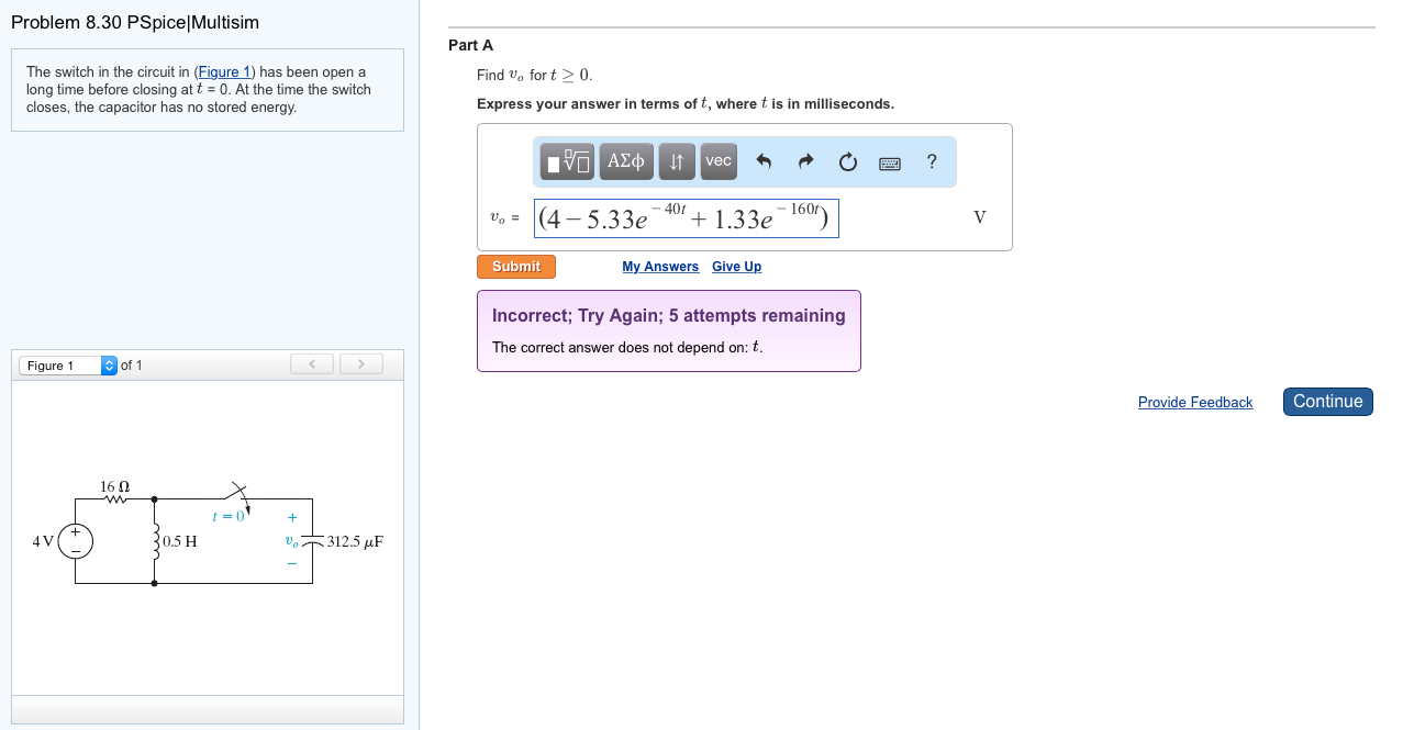
Solved: The Switch In The Circuit In (Figure 1) Has Been O ...

Image from page 318 of "United States Court of Appeals For the Ninth Circuit" (1902)
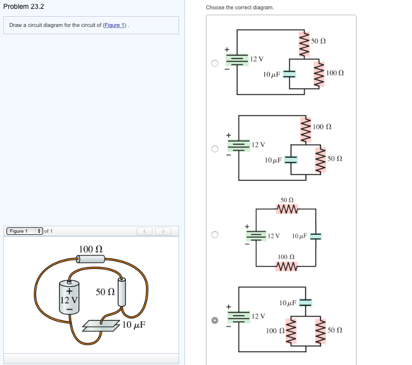
Solved: Draw A Circuit Diagram For The Circuit Of (Figure ...

Using Kirchhoff 's rules, calculate the current (Ig ) that ...
Simple Series Circuits | Series And Parallel Circuits ...
How to find the total resistance of this circuit diagram ...
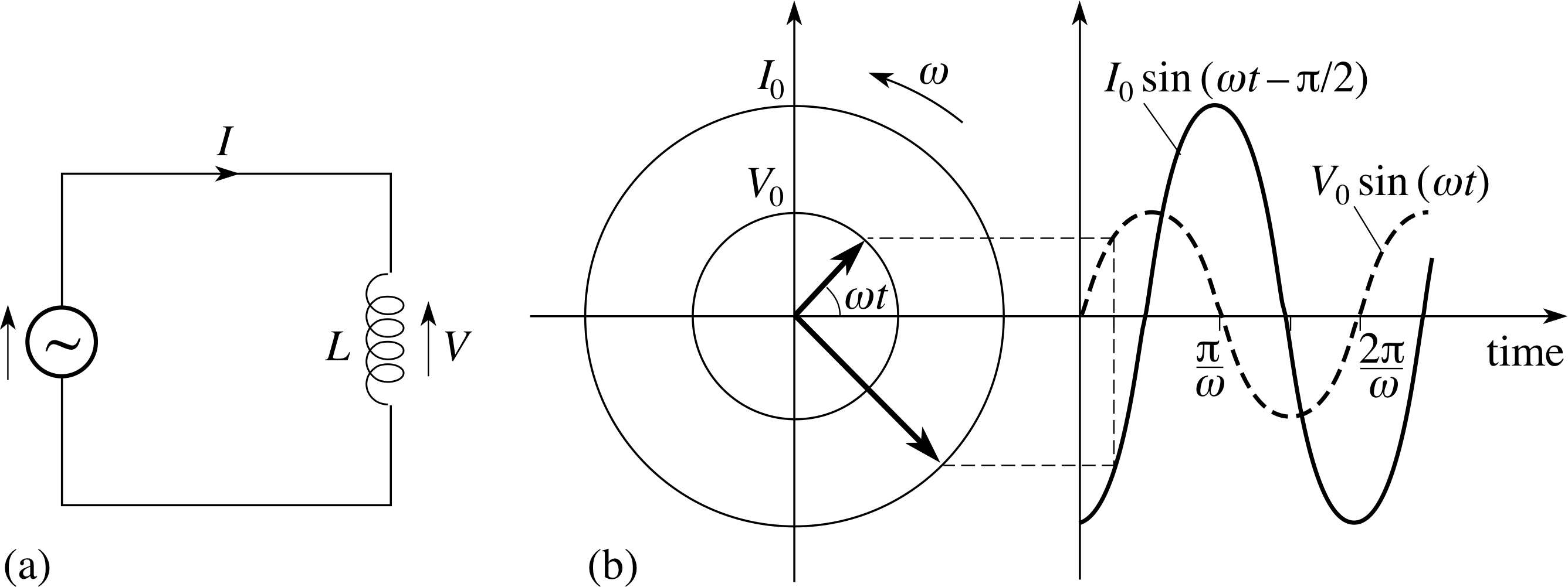
PPLATO | FLAP | PHYS 5.4: AC circuits and electrical ...
How to Calculate Amperage in a Series Circuit | Sciencing

A child has drawn electric circuit to study Ohm's law as ...
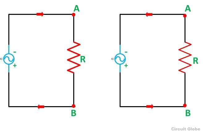
What is an AC Circuit? - Various terms & Waveform ...

Porssche 911 991 GT2RS at Bugatti circuit in Le Mans

Yellow Porsche 911
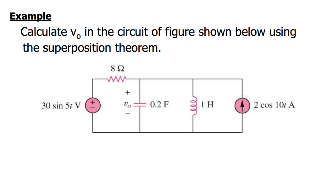
Solved: Example Calculate Vo In The Circuit Of Figure Show ...
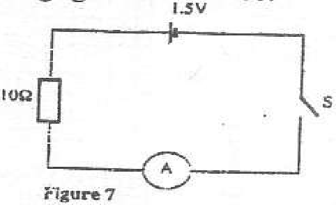
In the circuit diagram shown in figure 7, the ammeter has ...

Calculating Resistance of Unknown resistor, total current ...

What Is The Equivalent Resistance Of Group A Of Resistors ...

WD-40 Rider no. 31 on a bend at Silverstone

Solved: Calculate The Three Currents I1,I2, And I3 Indicat ...
0 Response to "40 consider the circuit diagram in the figure"
Post a Comment