37 booster pump installation diagram
BOOST-RITE™ Universal Booster Pump Installation and User's Guide iv For Installation of Electrical Controls at Equipment Pad (ON/OFF Switches, Timers and Automation Load Center) Install all electrical controls at equipment pad, such as on/off switches, timers, and control systems, etc. to allow the operation (startup, shut-down, or servicing) 1-800-955-8561. Mon - Fri • 9:00 AM - 5:30 PM ET. sales@h2odistributors.com.
straining element. They are used in pipelines to protect pumps from solid dust and waste materials entering the pump and the pressure tank. It is strongly recommended to install Strainers to avoid clogging, so it doesn't disturb the functioning of Pressure Boosters. Before starting; pre-filling of the pump with water is mandatory,

Booster pump installation diagram
Internal Wiring Diagram Inline 400 Inline 400 Model No. 92061501 / 92061503 92061502 / 92061504 ... The Inline 400 is a simple to use "plug-and-play" water pressure booster system. At the heart of this fully integrated booster system is a trusted ... Decide on a location for the pump installation that is suitable based on the enclosure ... 13) Congratulations, you have completed installation of the vacuum pump! Before you start the vehicle, review the simplified wiring diagram pictures below to make sure all of your connections are correct: To ground (-) Relay terminal 3 To vacuum switch Relay terminal 1 To (-) pump (black) Relay terminal 5 (+) 12 volt Relay terminal 2 To ... applications. If you are using a booster pump, then install this system following the booster pump. If you have questions, please call customer service. Specification Description PSE1800 PSE2000 Rated Service Flow Rate 8 GPM 12 GPM Peak Flow Rate 12 GPM Min/Max Working Pressure 25-80 PSI Maximum Vacuum 5 inch/127 mm Hg Operating Temperatures 36 ...
Booster pump installation diagram. 23.06.2015 · Reattach the ground line located on the side of the pump, and the electrical lines located on the front of the pump. Use the pulley installer tool to reattach the power steering pump pulley. Re-install the serpentine belt. Refer to the drive belt routing diagram located on the radiator shroud. Step 10 – Connect the pressure hoses and Tee fitting Reverse Osmosis Installation Diagram 3 5 4 8 9 16 18 17 10 11 15 19 14 13 20 21 6 2 1 7 12 System Components 1.) Cold Water Line 2.) Angle Stop Shut-off Valve 3 ... Check wiring against the pump installation manual diagram, check all connections for tightness, shorts, burns, damage. A loose wire can cause intermittent pump or other electrical device failures as well as a hard failure that means no power or blown fuses. Rewire or repair or replace wiring. See pump wiring tests in this article. See WATER PUMP WIRING DAMAGE. Burned … Sep 08, 2021 · Submersible Pump Control Box Wiring Diagram For 3 Wire Single Phase Submersible Pump Submersible Electrical Circuit Diagram. Automatic Water Level Controller Wiring Diagram For 3 Phase Motor Submersible Pump Water Pump Motor Submersible Pump Electrical Installation. Booster Pump Explain New 2017 Youtube Well Pump Refrigeration And Air ...
General arrangement schematic diagram 6 Design Envelope booster package commission check sheet 7 1.0 Introduction 11 2.0 Operation displays 12 3.0 Alarm management displays 17 4.0 System setup displays 18 Setup displays - level 1 and level 2 19 Wiring diagram 29 H0609200_REVA PB4SQ™PB4SQ™ Booster Pump Replacement Kit Instructions Replacement Parts List ITEM Part Description SECTION PAGE 1 R0722900 Capacitor Housing Cover 4 5,8,10 2 R0734500 Capacitor 30mfd 400VAC 4 5 3 R0734200 Motor Assembly, 725 WATT 6 10 4 R0722600 Fan Cover Kit 5 6,7 5 R0723000 Motor Fan 5 6 6 R0722700 Base 5 7 7 R0747800 Mechanical Seal Assembly 6 10 heater discharge (see the Typical Installation diagram). DO NOT TAP THE BOOSTER PUMP INLET INTO THE THREE-FOOT SECTION OF HEAT SINK PIPE THAT COMES DIRECTLY OUT OF THE HEATER. Installation with a Solar System The booster pump must be installed so it is always in the water flow (see the diagram below). Some solar heating systems are designed to use Booster Pump Installation Instructions 1. Install pressure switch in tank line. (See diagram on back for where to place the pressure switch). 2. Pump must be located within 2 feet of pressure switch and within 6 feet of power outlet. A. Pump can be mounted to the wall horizontally in either direction or vertically only one way ~ with pump head and
Pb4 60 Parts Diagram. The Power Behind Polaris The PB4SQ is an energy-efficient. I have a new polaris pb booster pump that I bought to replace an PB Q, both V old pump had wire diagram for connections. Electrical. The booster pump motor is factory wired for cleaner, refer to the Typical Installation diagram . • Pump is exceptionally quiet, and uses up to 40% less electricity than competitive booster pumps. • Pump design allows for easy installation and service. • Suitable for use with all pressure cleaners requiring a booster pump. • Tall mounting base allows for increased motor ventilation as well as protection from flooding. 12 Volt Vacuum Pump Installation Instructions Instructions: 1. Mount the vacuum pump. 2. Connect the vacuum fittings, hoses, switch, and filter as shown in the diagram. 3. Connect the black wire from the vacuum pump to a ground. 4. Connect the red wire from the vacuum pump to one of the terminals on the vacuum switch. 5. Diagrams --Typical Pump Installations. The information provided here is for educational purposes only. Technically qualified personnel should install pumps and motors. We recommend that a licensed contractor install all new systems and replace existing pumps and motors. Failure to install in compliance with local and national codes and ...
Deep Well Pump Installation Diagram | Deep well pump, Well ...
Attached is the TYPICAL Grundfos Booster pump wiring diagram please check confirm with your own wiring diagrams and electrician . this is the same pump for the main line booster
Booster Pump Systems for Residential and Light Commercial Use
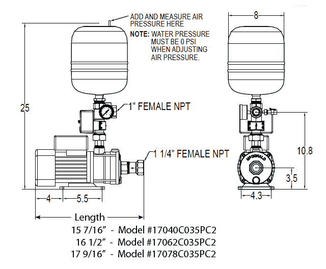
As water demand picks up, the pump in the inline unit will pump faster keeping the pressure from dropping due to the increased water demand. These systems are a must have for anyone with inconsistent or low water pressure. constant water pressure system - Inline #25GIL1100N4. This compact water pressure system features: Great for water storage/cistern systems, homes in …
Installing the Booster Pump Sprinkler System | Installation ...
the LA01N booster pump it manufactures, including all parts and components thereof, to be free of defects in material and workmanship. The warranty commences on the date of installation of the pump and shall remain in effect for a period of twelve months, but in no
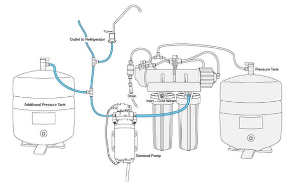
5 Stage Point of Use RO System with Feed Booster Pump
Refer to the wiring diagram or connection diagram for connecting this PCB to the unit. Remote thermostat kit (option) An optional room thermostat EKRTW or EKRTR can be connected to the indoor unit. Refer to the installation manual of the room thermostat for more information. Connection to a benefit kWh rate power supply This equipment allows for connection to …
Booster Pump - Installation Instructions – Pure Water ...
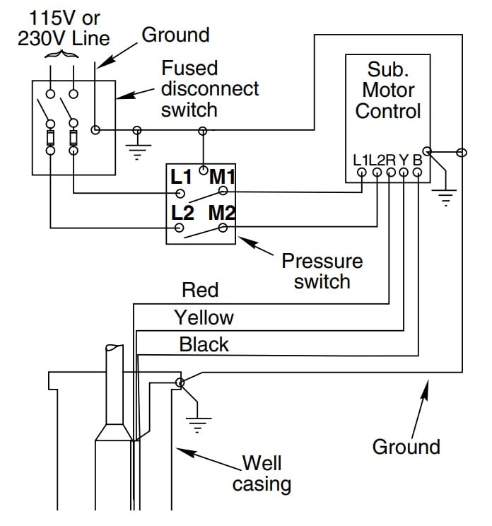
Before Installation. Well pump installation can be dangerous when dealing with water and electricity, so extreme caution must be taken. Before getting started, look up your owner's manual and read over the precautions and all other warnings before beginning the installation. The manual will contain important safety precautions, wiring diagrams, tools required for assembly, …

Zamboanga City Water District - SCHEMATIC FOR PROPER ...
Heat Pump Water Heaters; SBB Domestic Hot Water Tanks for Solar, Geothermal or Hydronic Applications; SB-E DHW Tanks with Integral Backup Heating Element; MegaBoost Tank Booster Water Heater; High-capacity Commercial/Industrial 3-Phase Tankless; Renewables. Accelera ® E Heat Pump Water Heaters; Solar Thermal Hot Water Systems and Individual Components; …

Grundfos CMBE Series Booster Pumps Buyers Guide - Pump Products
Exploded Parts Diagram. Polaris PB4-60 Booster Pump Parts List. Launch our online catalog viewer to review breakout diagrams and part numbers. Learn More. Parts List. Model Description ; P61: Polaris Motor, 3/4 HP, Threaded Shaft , 60 Hz: R0536600: Jandy Pro Series O-Ring, Backplate, 60Hz: R0445500: Jandy Pro Series Mechanical Seal, Carbon, SHP, PHP, MHP: …
Booster pump explain new 2017
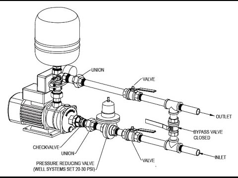
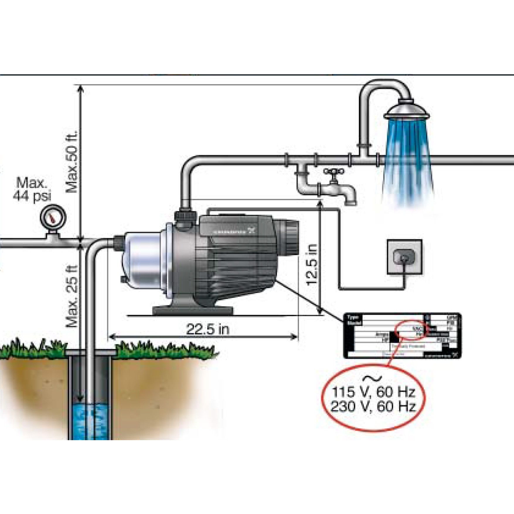
The installation of a booster pump on a city water system, or even a rural water system, that uses gravity-fed water, is quite easy. All you need to do is take the main water line as it enters the house and feed it into a booster pump. The output of the pump goes to a water-pressure tank, and the output of the tank then goes to the house water ...
Booster pump /control diagram - YouTube
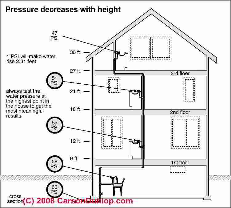
Installing a Booster Pump for Water Pressure on the Fourth Floor of a Residential Building Beginning on the 4th floor of such a building, install an additional pressure tank next to the second pump. The ground floor pump will send water into the incoming pipe connection of your 4th floor pump itself.

Compact Davey Booster Pumps for Homes | Primo Supply
Check my new video https://youtu.be/EqNenMs_Wrk booster pump repair,booster pump and pressure tank,booster pump installation,booster pump for washing machin...

FIG 1 Pressure Booster Pump Application - Manuals+
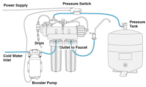
Observe the directional arrows on the quick-connect fitting ports at the front of the pump, cut the inlet tube squarely and insert the ends into the appropriate ports. Cut the 1/4" tube that connects the tank to the unit squarely and insert the pressure switch so that the tank water will pass through the switch. Flow direction does not matter.
How to Install and Wire a Well Pump - Well Pump Installation ...
13) Congratulations, you have completed installation of the vacuum pump! Before you start the vehicle, review the simplified wiring diagram pictures below to make sure all of your connections are correct: To ground (-) Relay terminal 3 To vacuum switch Relay terminal 1 To (-) pump (black) Relay terminal 5 (+) 12 volt Relay terminal 2 To ...

Booster Pump Pool Cleaner Plumbing Diagram
the booster pump system. 3. Outlet piping from the booster pump system should be equal or greater than the outlet pipe on the booster pump system. 4. Locate the booster pump control on a wall as close to the booster pump system as possible. 5. Follow all local plumbing and electrical codes.

Water Pressure Booster Pump Installation (10 Step Guide ...
How to install a Pressure Booster PumpKnow how to pump up the water pressure in your home with the help of a pressure booster pump. Pumpkart. Com is not only...
Davey DIY Easy Quick 1" Installation Package for Davey BT 14 ...
INSTALLATION WIRING DIAGRAM - 115VAC - TWO-WIRE PUMPS For 115 Vac motors exceeding 16 full load amps, use magnetic starter to avoid damage toMascontrol®. See separate magnetic starter wiring diagram.! WARNING 22 Remove pressure switch from surface pump and wire Mascontrol® directly to pump. IMPORTANT

WECO Economy Booster Pump Retrofit Kit for Reverse Osmosis ...
The Polaris booster pump supplies high pressure water to The booster pump motor is factory wired for cleaner, refer to the Typical Installation diagram. I have a new polaris pb booster pump that I bought to replace an PB Q, both V old pump had wire diagram for connections.

560043 - Booster Pump Kit
The starting current of the booster pump motor may exceed 15 amps. It is recommended that a 20 amp service breaker be used for the pump. The booster pump motor is factory wired for 240 volts, but can be wired for either 120 or 240 volts. To rewire to 120 volt, follow the instructions on the name plate

Grundfos SQE Constant Pressure Installation Diagram (Well ...
3. Cut the 3/8" factory brake booster hose again and insert the supplied Y-connector (Fig. #2) between the check valve and the brake booster. 4. Connect 1/8" hose from vacuum pump. (Fig. #3) 5. Next connect the red wire from pump to 12 volt source. For more information about wiring look at other side of this paper. 6.

ð’ð‘ðŠ ð„ð§ð ð¢ð§ðžðžð«ð¢ð§ð ð‚ð¨ð§ð¬ð®ð¥ððšð§ðœð² ...
applications. If you are using a booster pump, then install this system following the booster pump. If you have questions, please call customer service. Specification Description PSE1800 PSE2000 Rated Service Flow Rate 8 GPM 12 GPM Peak Flow Rate 12 GPM Min/Max Working Pressure 25-80 PSI Maximum Vacuum 5 inch/127 mm Hg Operating Temperatures 36 ...

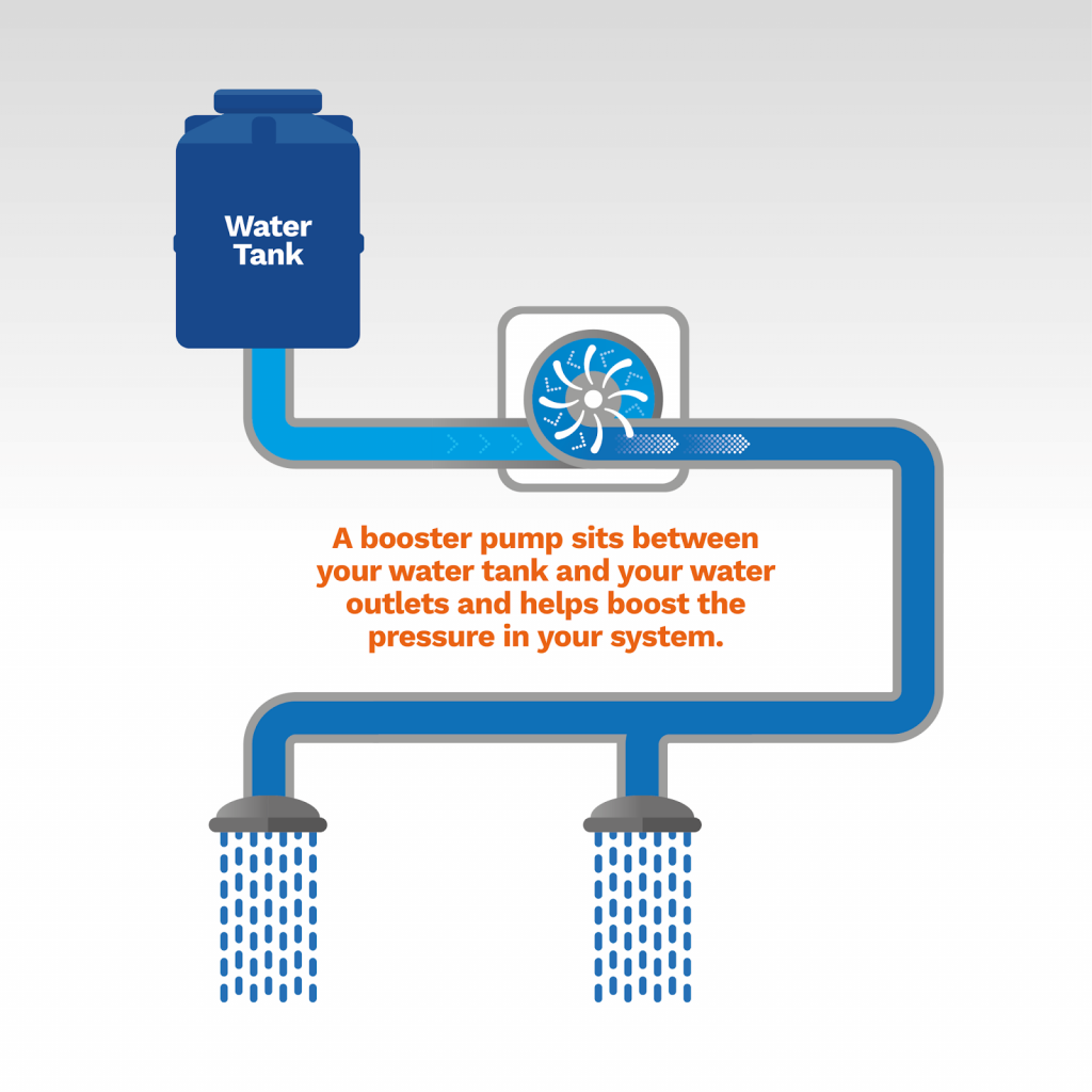
What is a Booster Pump? | How does a Water Pressure Pump work?
13) Congratulations, you have completed installation of the vacuum pump! Before you start the vehicle, review the simplified wiring diagram pictures below to make sure all of your connections are correct: To ground (-) Relay terminal 3 To vacuum switch Relay terminal 1 To (-) pump (black) Relay terminal 5 (+) 12 volt Relay terminal 2 To ...

Hitachi WTP100XS: Automatic Water Pump, Power 100W, Head 14mH, Flow 30L/min, Inlet x Outlet 3/4" x 3/4", 15kg
Internal Wiring Diagram Inline 400 Inline 400 Model No. 92061501 / 92061503 92061502 / 92061504 ... The Inline 400 is a simple to use "plug-and-play" water pressure booster system. At the heart of this fully integrated booster system is a trusted ... Decide on a location for the pump installation that is suitable based on the enclosure ...
How Demand Pumps Work
Water pressure booster pump and tank guide - water pressure ...
Booster Pump

Backup Water Systems | RPS Solar Pumps | America's #1 Solar ...
Buying a Home Booster Pump: The Complete Guide - Anchor Pumps

Hayward Booster Pump
Domestic Water “Pressure Booster Pumping System†– Suction ...

Jet Pumps / Centrifugal Pumps Installation shallow well or ...

The Booster Pump | ecexproblemsolved
How to Install Water Pressure Booster Pumps | PumpStoreUSA.com
Booster Pump Package Operating & Installation Instructions
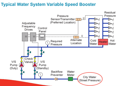
Packaged Pressure Booster Systems
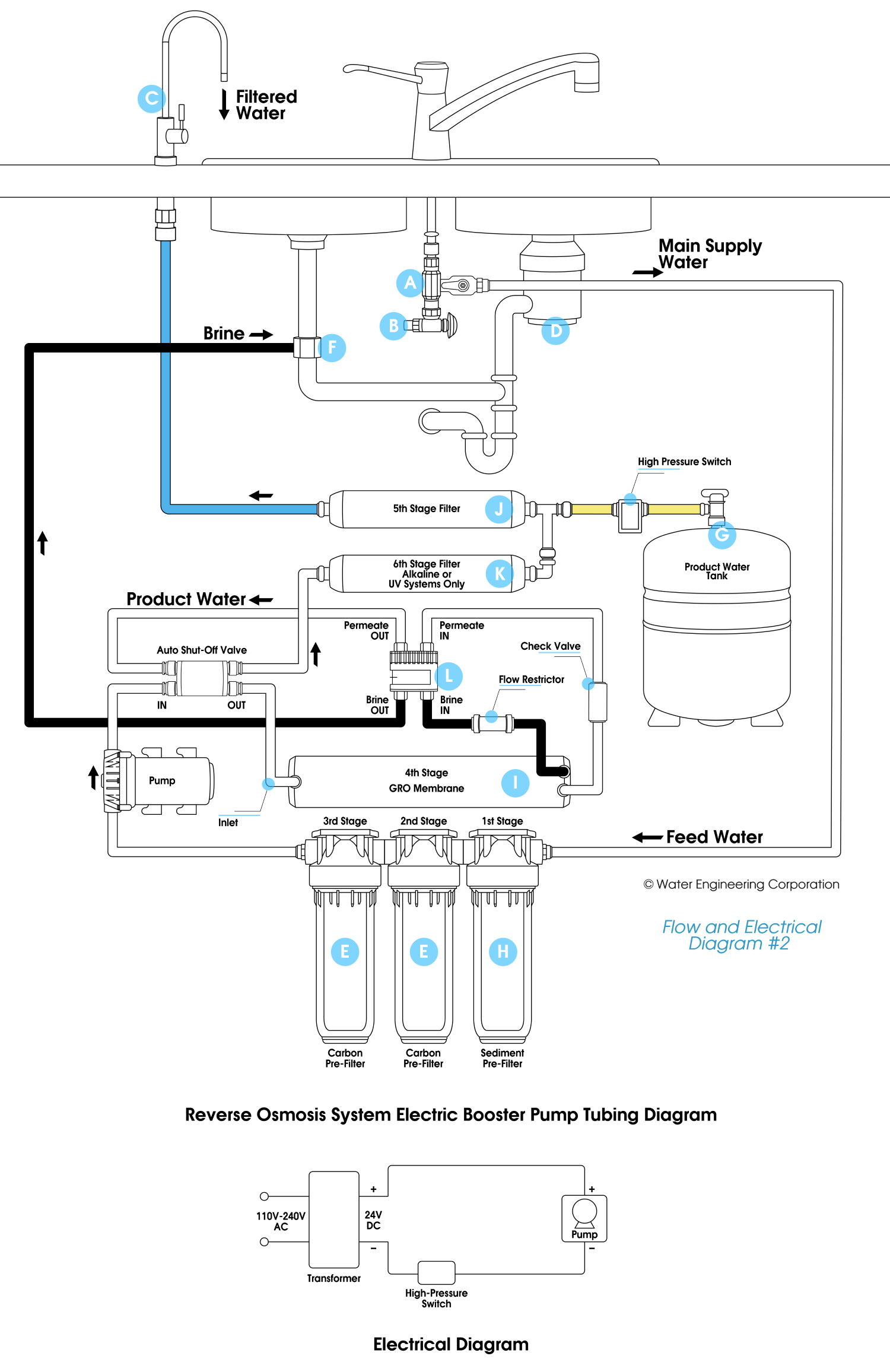
How do I boost pressure in a reverse osmosis system?

WECO Reverse Osmosis (RO) Pressure Booster Pump Kit: Amazon ...
Grundfos MQ3-45 - 1 HP Pressure Booster Pump

Grundfos Booster Pump BMQE Manual | Manualzz
0 Response to "37 booster pump installation diagram"
Post a Comment