41 intermatic timer wiring diagram
The wiring diagram is a little difficult to comprehend but once you understand what it's showing you, it's simple and straightforward to hook up. The weatherproof box means it can be mounted outside but my handy pool shed ensures both my pump and timer are dry, save perhaps catastrophic failure of pump seals. As an added bonus, the timer keeps ... Intermatic Timer T104 Wiring Diagram - wiring diagram is a simplified tolerable pictorial representation of an electrical circuit. It shows the components of the circuit as simplified shapes, and the aptitude and signal links amongst the devices. A wiring diagram usually gives recommendation practically the relative face and deal of devices ...
Intermatic Timer Wiring Diagram. By | November 27, 2020. 0 Comment. Guidance needed for wiring of pool pump timer bypass in 240v system diy home improvement forum need help an intermatic wh40 water heater time switch into the doityourself com community forums t104r won t turn on but does it off how to connect t101 with diagram t104 indoor 24 ...

Intermatic timer wiring diagram
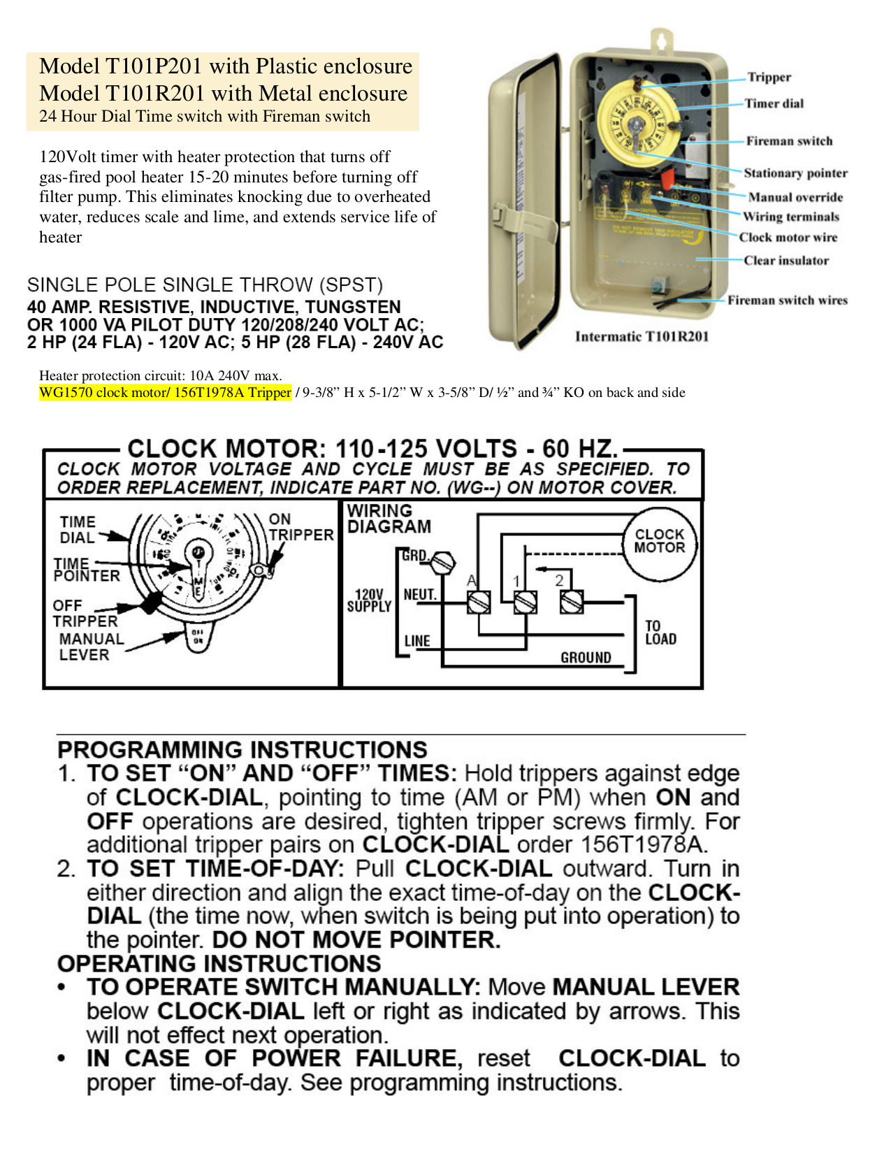
Intermatic Time Clock Wiring Diagram. WIRING. DIAGRAM. V 2 WIRE. AND GROUND. LR UL and align the exact time-of-day on the CLOCK-DIAL (the time now, when. WIRING INSTRUCTIONS: To wire switch follow diagram above. Use solid or of CLOCK-DIAL, pointing to time (AM or PM) when ON and. OFF operations are. Connect the ground wire to the green screw ... The wiring diagram for that timer is misleading. The volt clock timer motor is connected internally to the "A" (neutral). T timer requires neutral wire. T has WG V clock motor. Intermatic T timer can be wired to control Volt circuit -or- Volt circuit. The key.Jul 18, · T Timer Wiring Diagram intermatic wall timer instructions intermatic wall ... Intermatic timer model t104r manual intermatic t104r eBay Intermatic T104r Wiring Diagram It is wired from the breaker box at 220v. Also, the timer motor wires are connected to line 1 and line 3, which is the way it came in the box.
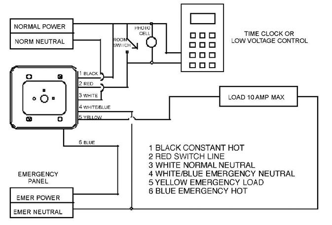
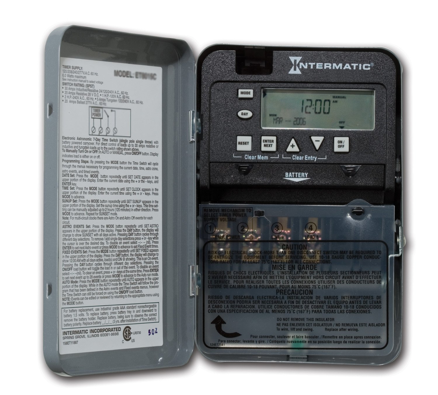
Intermatic timer wiring diagram. Connect BLACK wire from switch timer to COMMON wire, using a twist connector. Connect the other two wires from the old switch to the Blue and RED wires from the switch timer. Connect the GREEN wire to the grounding screw in the box. If a plastic box, connect to ground as supplied. Using diagram #1 below. Identify and remove wire "C" from 4. Wire the timer into the wall box. An example of single-pole and three-way wiring follow. For other three-way wiring scenarios, go to www.intermatic.com . Single-Pole Wiring 120 V Line Wire A Wire D Wire B Wire C Neutral Load Timer A Black — Connects to the hot (black) wire from the Power Source B Blue — Connects to the other wire (black ... Intermatic 240v Timer Wiring Diagram Download. intermatic 240v timer wiring diagram - Building circuitry representations show the approximate locations and affiliations of receptacles, lights, and also irreversible electrical solutions in a building. Adjoining wire paths might be shown approximately, where certain receptacles or components have to be on an usual circuit. intermatic et1125c 24 hour 30 amp electronic time switch 120 277 vac nema 1. Architectural wiring diagrams affect the approximate locations and interconnections of receptacles, lighting, and long-lasting electrical facilities in a building. Interconnecting wire routes may be shown approximately, where particular receptacles or fixtures must be upon a common circuit.
Get Intermatic Timer T104 Wiring Diagram Sample. Assortment of intermatic timer t104 wiring diagram. A wiring diagram is a simplified standard photographic depiction of an electric circuit. It reveals the components of the circuit as streamlined forms, and also the power and also signal connections in between the tools. Jan 10, 2020 · Check out the diagram below, or see the wiring diagram which comes with a new timer, or is printed on the door of the timer box. After securing the wire conduit (flexible or rigid) to the box knock out with the proper 3/4″ conduit connector, first secure the green ground wire to the green ground screw, shown as GR. Intermatic Photocell Wiring Diagram / Leviton Dimmers Wiring Diagram - HONORFLIGHTAUCTIONS December 03, 2021 Repairing an electrical problem with your oven is definitely easier when you find the right oven wiring diagram. 16.08.2018. 6 Comments. on Intermatic 240v Timer Wiring Diagram. Time Switches and Controls · Sensors · HVACR Solutions · Power Protection Duo · Timers · Hour Meters · Surge Protective Devices · Weatherproof Receptacle. The switch is wired to the timer. I switched out the T with the same and I think I messed up the wiring.
Intermatic Pool Timer Wiring Diagram Gallery. intermatic pool timer wiring diagram - Just What's Wiring Diagram? A wiring diagram is a type of schematic which utilizes abstract pictorial signs to reveal all the interconnections of components in a system. Circuitry representations are made up of two things: icons that represent the components in the circuit, as… Intermatic Insulator for Double-Pole Timer Switches, Item # 124T1952 for use in T100 Series Intermatic Timers (T103, T104, T105, T173, T174, T175, T176, T185, WH40), Timer Controls Accessories $6.99 In Stock. Multi-voltage general purpose time switch. 110v Pool Timer Wiring Diagram Intermatic T Amp 24 Hour Mechanical Time. 99. Essentially, it seems I need to replace the Intermatic timer with a smart switch and then use SmartThings to turn the light on when the Arlo detects motion. myTouchSmart Indoor In-Wall Motion-Activated Timer, White. Under a minute vid showing how to wire these timers (110/120V model)

woods timer wiring diagram Questions & Answers (with ...
Intermatic Incorporated manufactures timer switches designed for indoor and outdoor use. Many pool pump motors and water heaters use Intermatic timers to regulate their run times. An Intermatic timer-switch saves electricity when it turns a water heater off at night and when it limits the amount of time a pool's filtration system runs.

860-880 North Lake Shore Drive, Electrical Riser Diagram (11/28/1949) // Ludwig Mies van der Rohe (American, born Germany, 1886–1969) Associate Architect: Holsman, Holsman, Klekamp and Taylor (American, 20th century) Associate Architect: Pace Associates (American, 20th century) Structural Engineer: Frank J. Kornacker (American, active 1940s–1950s)
Mechanical Time Switches. Manage everyday load control needs with industry-leading mechanical time switches from Intermatic. Reliable and low maintenance, these solutions are an ideal choice to pair with water pumps, lights, fans, water heaters and other electrical loads. Learn More
26 Intermatic Eh40 Wiring Diagram - Wiring Database 2020
How to wire Intermatic T and T timers - Hardware & Accessories, Tip, How -To and Do It The wiring diagram for the T is here. The T Series Mechanical Time Switch has proven it can stand the test of time. These dependable time switches can handle electrical loads up to 40 A per.Jul 18, · T Timer Wiring Diagram intermatic wall timer instructions ...
How To Install an Intermatic T104 Timer - INYOPools.com
Nov 29, 2021 · Intermatic ST01A 7 Day Programmable In Wall Intermatic Cycle Timer Clock ON/OFF Plastic Switch Trippers - P1000 PB PF1100 Series, 2 Red, 2 Green eero WiFi Stream 4K Video in Every Room: Blink Smart Security You can replace a single-pole switch with a timer switch with no neutral connection based on the timer's wiring diagram in a few minutes ...
Intermatic T101 Timer Wiring Diagram
Intermatic Sprinkler Timer Wiring Diagram. RPC | Sprinkler/Irrigation Time Switch with Day Skipper These irrigation timers are designed to permit one to 44 "ON" operations every 24 hours . Intermatic T86A Transformer for sprinkler timer Or install 20 amp line fuse between incoming Hot wire and timer, and this will allow timer to control any.

Intermatic Wiring Diagram - How To Wire T101 Timer : D ...
How to wire T timer. use wiring diagram above to control 3-pole contactor, or diagrams to left and . How to wire Intermatic T How to wire T timer. The T Series Mechanical Time Switch has proven it can stand the test of time. These dependable time switches can handle electrical loads up to 40 A per. This Pin was discovered by Fuyang Ke.

River City I: Phasing Plan (c. 1974) // Bertrand Goldberg American, 1913-1997
Intermatic Pool Pump Timer Wiring Diagram Free Download | Wiring Diagram - Intermatic Pool Timer Wiring Diagram. Wiring Diagram will come with a number of easy to follow Wiring Diagram Instructions. It's meant to help all of the typical user in creating a correct method. These instructions will likely be easy to comprehend and implement.
Intermatic Mechanical Timer Replace :) - Sprinklers ...
Intermatic Pool Timer Wiring Diagram - intermatic pool pump timer wiring diagram, intermatic pool timer wiring diagram, Every electric structure is composed of various diverse components. Each component should be set and connected with different parts in particular manner. If not, the arrangement won't work as it should be.

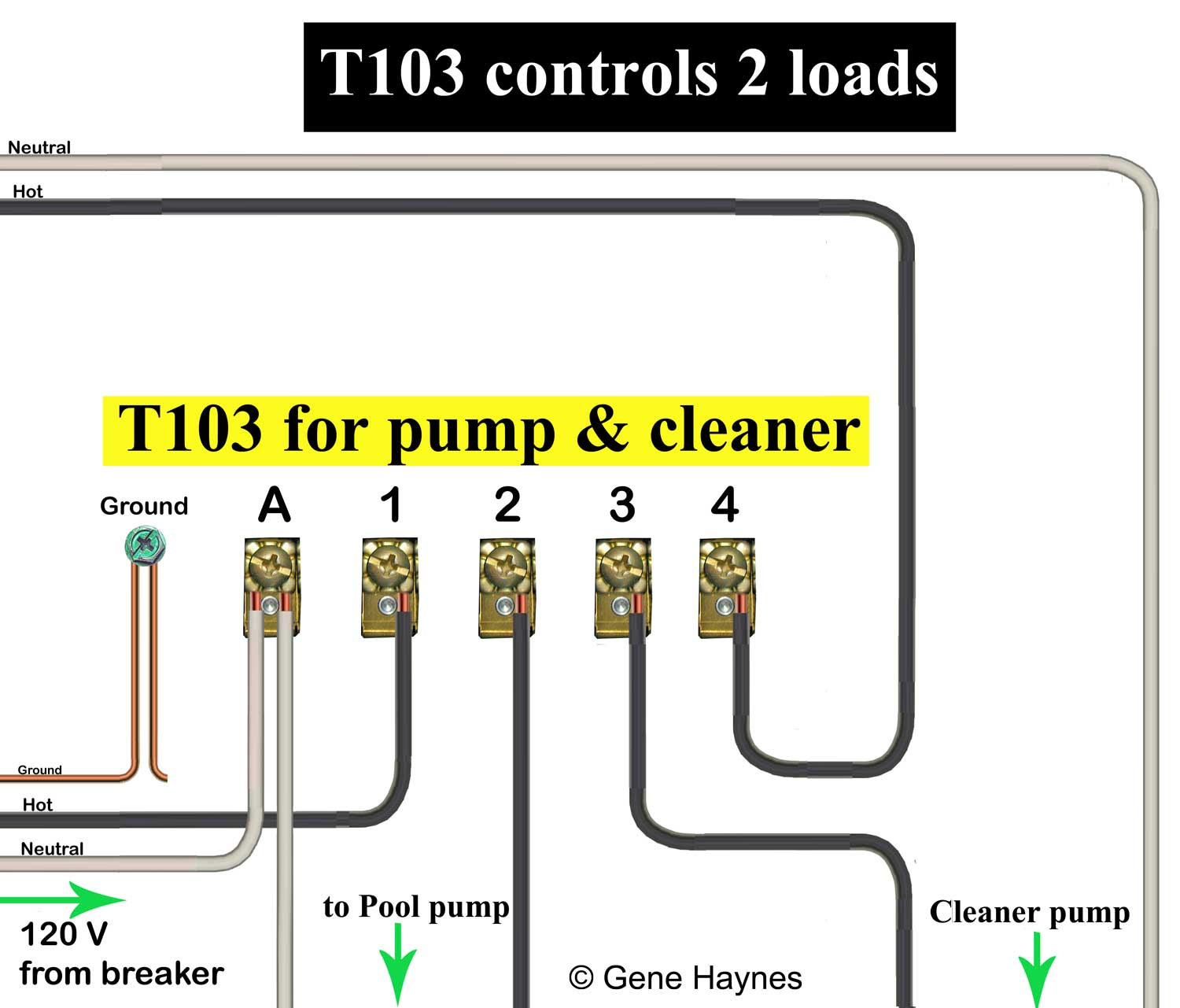
How to wire Intermatic T104 and T103 and T101 timers
Oct 05, 2021 · The ST01 7-Day Programmable In-Wall Timer from Intermatic is a heavy-duty 15 Amp lighting control that can be installed in both residential and light commercial applications. Users can program up 40 ON/OFF events each week to automate routine lighting schedules and improve energy efficiency within the home.

person holding red metal frame
Intermatic T Basic wiring diagram, T timer Volts or Volts Check label on side of water heater for Volts & Watts This timer. The T Series mechanical time switch has proven it can stand the test of time. These dependable time switches can handle electrical loads up to 40 A per.

round teal gauge on white textile
Intermatic timer model t104r manual intermatic t104r eBay Intermatic T104r Wiring Diagram It is wired from the breaker box at 220v. Also, the timer motor wires are connected to line 1 and line 3, which is the way it came in the box.

woman wearing red and grey long-sleeved floral dress smiling between buildings
The wiring diagram for that timer is misleading. The volt clock timer motor is connected internally to the "A" (neutral). T timer requires neutral wire. T has WG V clock motor. Intermatic T timer can be wired to control Volt circuit -or- Volt circuit. The key.Jul 18, · T Timer Wiring Diagram intermatic wall timer instructions intermatic wall ...

Intermatic T101 Timer Wiring Diagram - General Wiring Diagram
Intermatic Time Clock Wiring Diagram. WIRING. DIAGRAM. V 2 WIRE. AND GROUND. LR UL and align the exact time-of-day on the CLOCK-DIAL (the time now, when. WIRING INSTRUCTIONS: To wire switch follow diagram above. Use solid or of CLOCK-DIAL, pointing to time (AM or PM) when ON and. OFF operations are. Connect the ground wire to the green screw ...
Grässlin (UK) Ltd INSTALLATION & OPERATING INSTRUCTIONS

Intermatic Pool Timer Wiring Diagram | Free Wiring Diagram

Mobile Delousing Unit, Truck Equipment, Plan of Operation and Erection Procedure, Presentation Drawing (1943) // Bertrand Goldberg American, 1913-1997
How To Replace an Intermatic T101M (120V) Pool Timer - YouTube

Intermatic Timer Wiring Diagram T101 - General Wiring Diagram

Installation Diagram for Stone Line (c. 1976) // Richard Long English, born 1945

Intermatic Digital Timer Wiring Diagram - Wiring Diagram

Bow Fibula (wire) (Geometric Period (800–600 BCE)) // Greek; Thessaly
![[DIAGRAM] Intermatic E10694 Pool Timer Wiring Diagram FULL ...](https://blogger.googleusercontent.com/img/proxy/AVvXsEj8myauyPnPSWuInjnV8eHgp49NZQjJgfQ20In6vFwConJZ7X3fMgpxR0RmROSRfq1MW-d_xAwALuPAkzJs0j3POCl6sciINU4AGkJ-Jjwb75UZlWZihQ5_SkwwY0ZsG6ktAlqPj3pTZe4JnTNhlo1lipgLrhltElqgz7xFTwoQ-YvnFZOKTj6q=s0-d)
[DIAGRAM] Intermatic E10694 Pool Timer Wiring Diagram FULL ...

I have a T8845pv sprinkler timer that appears to be wired ...
Intermatic Timer T103R 24 Hour Dial 120V 40-Amp 2 Poles Timer Rain Tight Case
Intermatic T103 Wiring

Intermatic Timer T104 Wiring Diagram Download

30 Intermatic T101 Timer Wiring Diagram - Wiring Diagram ...
How to wire WH40 water heater timer:
INTERMATIC R8806P101C SWITCH SUPPLEMENTARY MANUAL | ManualsLib
30 Intermatic Pool Timer Wiring Diagram - Wiring Diagram List
220\240 wiring diagram for a Intermatic T104R Timer | Natural red, Black and red, Shot photo
Wiring Diagram For Intermatic Timers

Club de Centre Rural: Perspective Sketch (1943) // Le Corbusier French, born Switzerland, 1887-1965
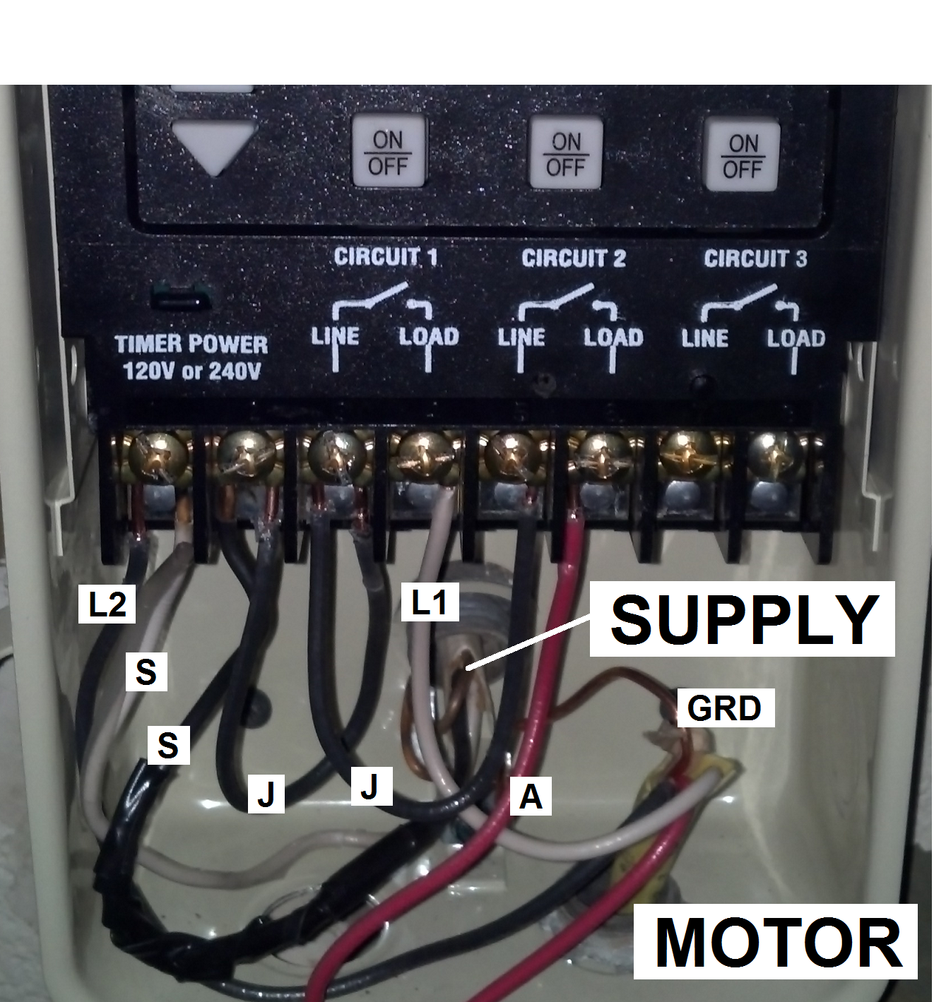
How to connect Intermatic T101 timer (with diagram)

Intermatic T101 Timer Wiring Diagram - Wiring Diagram

Marina City Theater, Chicago, Illinois, Roof and Partial Concrete Frame Development Drawing (1961-1962) // Bertrand Goldberg American, 1913-1997

American Steel & Wire Company, Worcester, Mass. (1912) // Herman Schervee American, born Norway, 1867–1923
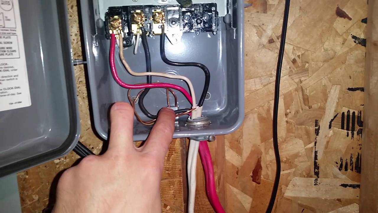
How To Wire and Connect A Intermatic Pool Pump Timer ...

To Grow (1970) // Virginia Churchill Bath (American, active c. 1970) United States, Illinois, Beecher

greyscale photo of woman standing behind woman sitting on chair

How to connect Intermatic T101 timer (with diagram)
0 Response to "41 intermatic timer wiring diagram"
Post a Comment