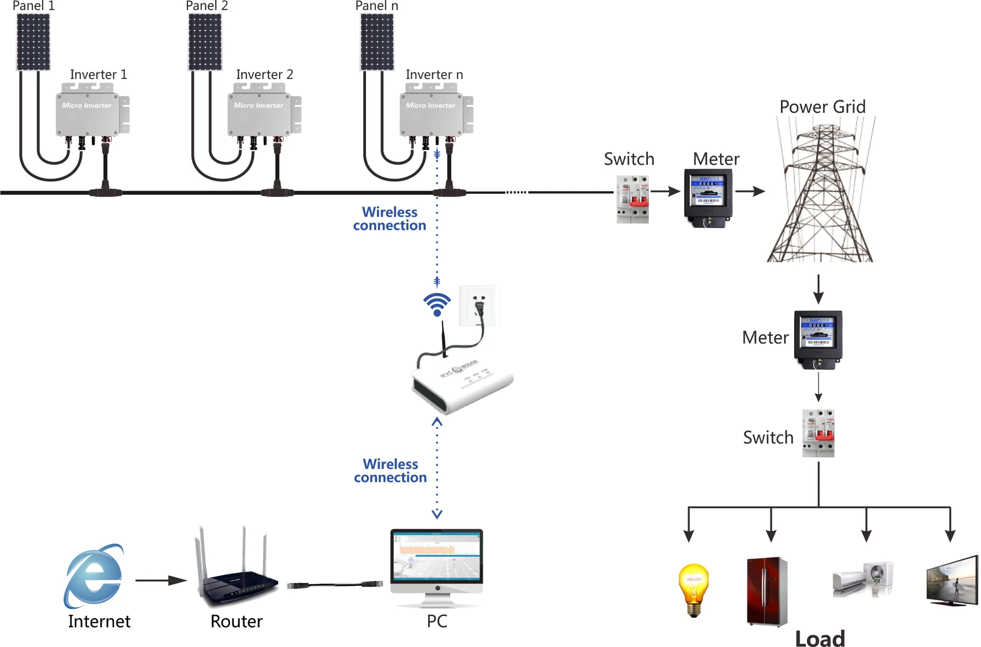
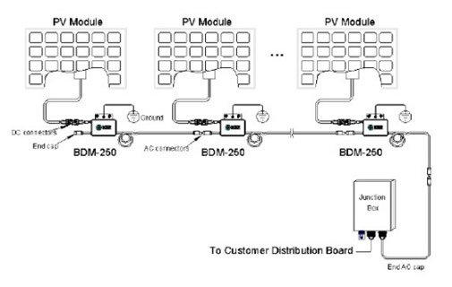
41 enphase micro inverter wiring diagram
DIY Solar Electrical Wiring - Should you do it yourself? Look at conduit bending and panel wiring need for DYI install. DIY Solar Electrical Installation for...
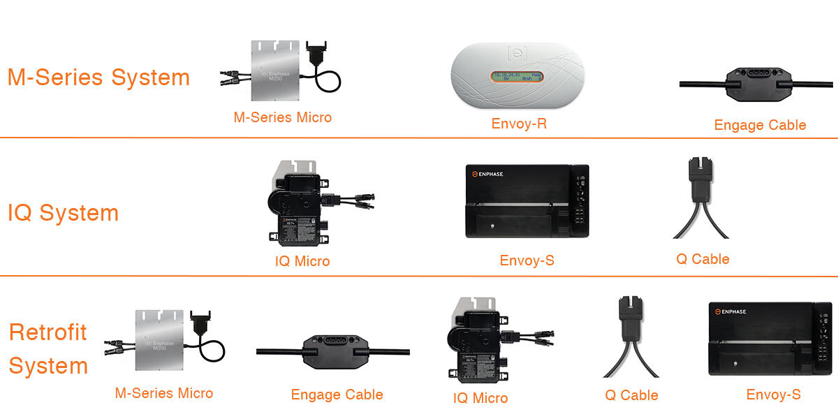
Enphase, the world's leading solar power inverter manufacturer, provides high-powered smart grid-ready IQ 7+ microinverters that simplify the installation process while achieving the highest system efficiency.
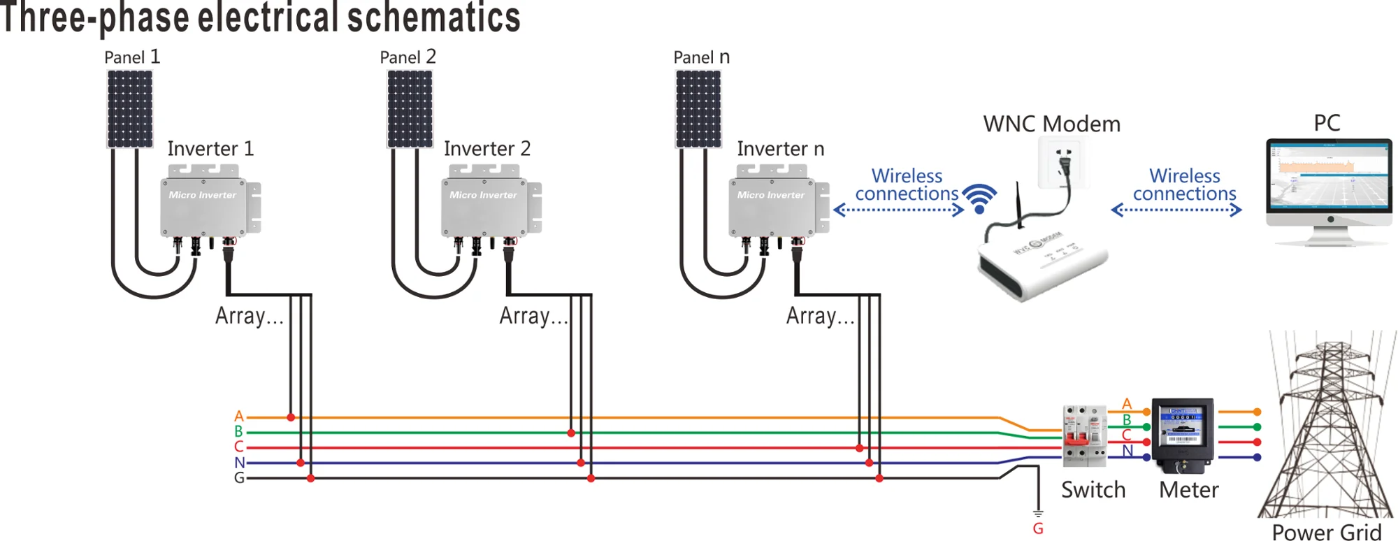
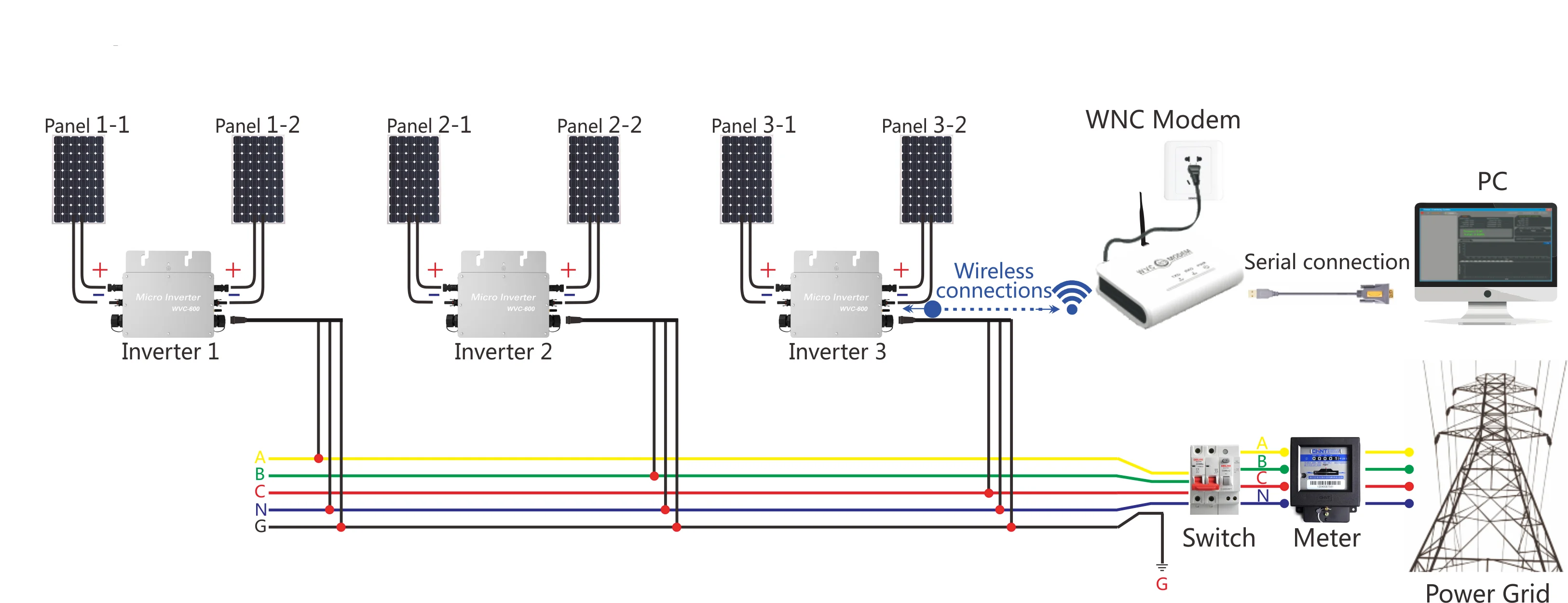
AC or DC wires are. For more information about Enphase Microinverters, visit the Microinverter Family The IQ System uses the 2-wire Q-Cable and a new line-to-line power line.Collection of enphase micro inverter wiring diagram. A wiring diagram is a streamlined standard photographic representation of an electrical circuit.

Enphase micro inverter wiring diagram
Installing a generator myself soon But in my case I have the feed for the solar panels going through an 80 amp contactor so that they shut down at night. The Enphase micro inverters use power at night. In my case close to 4 Amps. So I installed a contactor controlled off a timer so the system shutsdown at night and restarts in the morning.
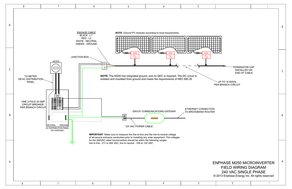
A wiring diagram is a streamlined standard photographic representation of an electric circuit. Attach the microinverters to the PV racking. Use the IQ Combiner 3 for single-phase applications and to support the AC connections needed for an Enphase residential solar installation. Enphase M250 micro inverter. Use Class 1 wiring methods for field ...
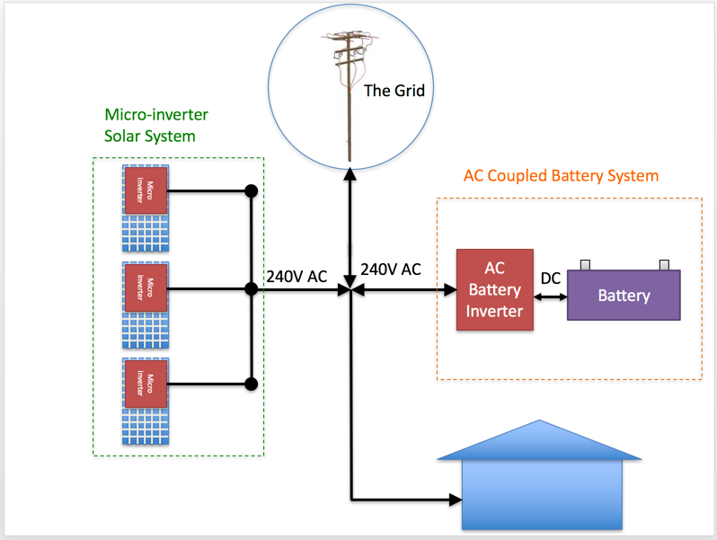
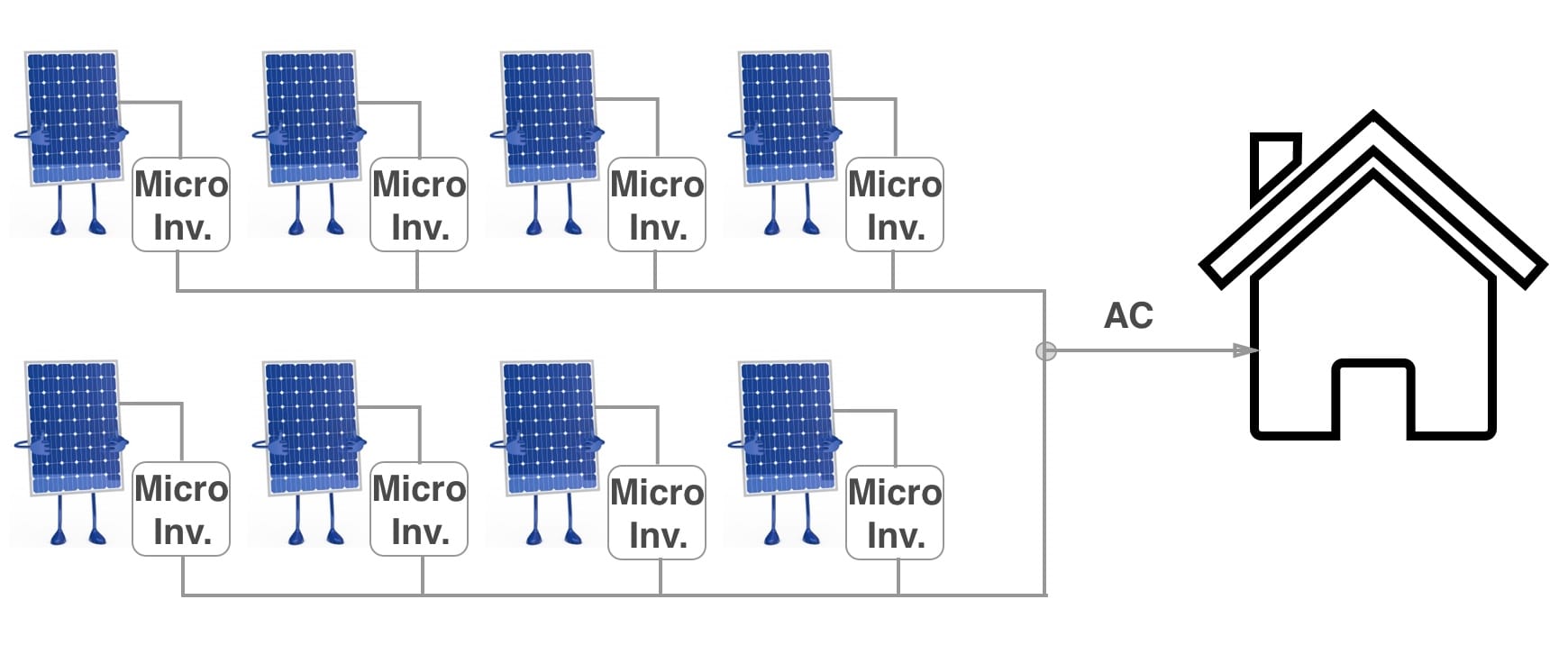
Collection of enphase micro inverter wiring diagram. A wiring diagram is a streamlined standard photographic representation of an electric circuit. It reveals the parts of the circuit as simplified forms, as well as the power and signal links in between the gadgets.
Enphase micro inverter wiring diagram.
Collection of enphase micro inverter wiring diagram. A wiring diagram is a streamlined standard photographic representation of an electrical circuit. It reveals the components of the circuit as simplified shapes, as well as the power as well as signal connections between the tools.
Enphase M250 micro inverter. (10) 265W SolarWorld Modules each connecting to its own Enphase M250 micro inverter. 45A Service conductors extending to utility Existing Loads Existing Service panelboard meter J-box mounted at roof eave (for transition of NM cable to THWN-2 wire in conduit. 20A 20A 20A Note: this wiring diagram is simply an example.
micro-inverters per envoy communications gateway ethernet cable to broadband router the first ac connector in each branch circuit is suitable as a disconnecting means the ac load center breaker should be opened prior to disconnecting ac connectors enphase ac interconnect cable black - l1 red - l2 orange - unused blue - neutral d c b a a 8 7 6 5 4 3 1 8 7 6 5 4 3 2 1 [e] enphase energy dwg no ...
ENPHASE MICRO-INVERTER INSTALLATION 1. System Wiring Diagram 2. Once you have completed installing the roof mount system, attach the Micro-Inverters to the railing system using the nuts and bolts provided. You will need your Hex key and Spanner. Ensure the bolts are tightened securely. The Micro-Inverter must be under the module, out of
Collection of enphase micro inverter wiring diagram. A wiring diagram is a streamlined standard photographic representation of an electric circuit. It reveals the parts of the circuit as simplified forms, as well as the power and signal links in between the gadgets.
G ) Size the AC wire gauge to account for voltage rise. Select the correct wire size based on the distance from the beginning of the Enphase Q Cable to the breaker in the load center. Design for a voltage rise total of less than 2% for the sections from the Enphase Q Cable to the breaker in the load center.
About Diagram Enphase Wiring . com *FREE* shipping on qualifying offers. Meet the Envoy, the brains of the Enphase Home Energy Solution. If you're looking to do any type of installation that requires wiring (some inverters can be grid-tied), be sure to hire a licensed, knowledgeable electrician.
G ) Size the AC wire gauge to account for voltage rise. Select the correct wire size based on the distance from the beginning of the Enphase Q Cable to the breaker in the load center. Design for a voltage rise total of less than 2% for the sections from the Enphase Q Cable to the breaker in the load center.
Enphase Micro Inverter Wiring Diagram Sample July 30, 2018 March 31, 2018 by faceitsalon Assortment of enphase micro inverter wiring diagram you can download for free. It reveals the components of the circuit as streamlined forms, and also the power as well as signal links in between the tools.
Title: IQ7 Series Microinverter Wiring Diagram - RESsupply.com - RES Supply Author: Enphase Subject: Enphase IQ7 Series Microinverter Wiring Diagram
These are just a few of the ways in which the Enphase Micro-inverter System provides tremendous time, material and cost savings, while maximizing energy production and providing better return on investment from your system. Enphase Micro-Inverter Models The Enphase M190 Micro-inverters operate with most 60 and 72-cell PV module configurations.
Position the Enphase AC cabling. Install an AC branch circuit junction box / isolator. Attach the microinverters to the PV racking. Create a paper installation map. Ground the microinverters (if required) Dress the Enphase cabling. Connect the microinverters to the Enphase cabling. Terminate the unused end of the Enphase cabling and seal any ...
Enphase.com. Maximum IQ Micros per 20A AC branch circuit IQ 7X Micros (single-phase 240 VAC) 12 IQ 7X Micros (single-phase 208 VAC) 10 IMPORTANT: The Enphase IQ Envoy and IQ Series Micros do not communicate with, and should not be used with, previous generation Enphase Microinverters, AC Batteries, and Envoys. The Q accessories work
Installing Enphase micro inverters and Enphase Envoy. After you’ve completed the rooftop work, you’ll complete electrical work on the ground and you’ll install the Envoy. Then you’ll energize the system and complete commissioning using the Installer Toolkit mobile app. IQ Microinverter Rooftop Installation. Get started with this short introduction to the installation of IQ Micros ...
Enphase Micro Inverter Wiring Diagram Sample July 30, 2018 March 31, 2018 by faceitsalon Assortment of enphase micro inverter wiring diagram you can download for free.
Enphase Micro Inverter Wiring Diagram Sample July 30, 2018 March 31, 2018 by faceitsalon Assortment of enphase micro inverter wiring diagram you can download for free. McDowell Blvd. The Enphase wiring diagram is here I did the wiring in this order: 1- The junction box at the PV array, wiring from PV array to the disconnect.
A wiring diagram is a streamlined standard photographic representation of an electrical circuit. It reveals the components of the circuit as simplified shapes, as well as the power as well as signal connections between the tools. View and Download Enphase M installation and operation manual online. Microinverter. M Inverter pdf manual download.
Field Wiring Diagram.. Nov 28, 2020 — Here is a very simple diagram of the micro-inverter system. The Enphase wiring diagram is here The thinking here was that the wiring is "cold" for .... This type of diagram is much like going for a photograph with the parts and wires all connected up. Enphase Micro Inverter Wiring Diagram Download. A ...
Understanding the different Enphase microinverters, how to install them on the rails, connecting them together in branch circuits, terminating the unused end...
When installing the Enphase Q Cable, secure any loose cable to minimize tripping hazard. NOTES: When looping the Enphase Q Cable, do not form loops smaller than 4.75" (12 cm) in diameter. Provide support for the Enphase Q-Cable every 1.8m (6 feet). If you need to remove a sealing cap, you must use the Enphase disconnect tool.
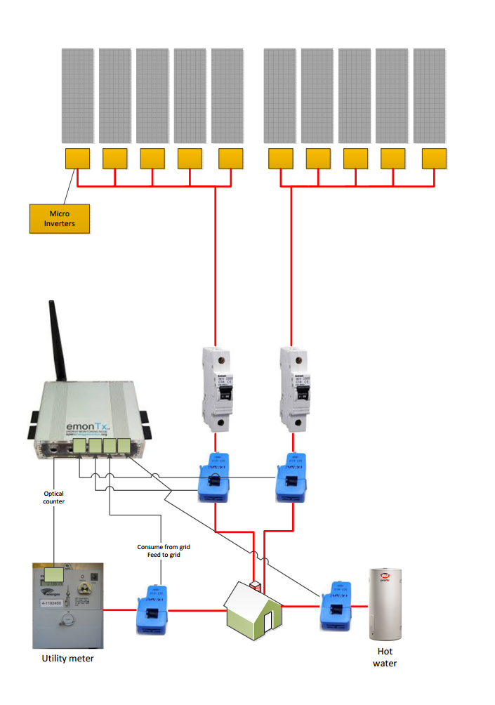
Micro-Inverter Electrical Diagram Contractor Name, Address and Phone: One-Line Standard Electrical Diagram for Micro-Inverter PV Systems Site Name: Site Address: System AC Size: SIZE FSCM NO DWG NO REV E1.1a SCALE NTS Date: SHEET Drawn By: Checked By: DESCRIPTION OR CONDUCTOR TYPE USE-2 or PV WIRE GEC EGC X ALL THAT APPLY EXTERIOR CABLE LISTED W/ INV. THWN-2 or XHHW-2 or RHW-2 GEC EGC X ALL ...
About Diagram Wiring Enphase . Enphase believes that the effects of UV on the Micro-inverter are not significant since the product is installed underneath the module and the wiring used is UV rated. When the reset switch is fully depressed, the test switch should pop out, level with the top of the outlet.
Position the Enphase AC cabling. Install an AC branch circuit junction box / isolator. Attach the microinverters to the PV racking. Create a paper installation map. Ground the microinverters (if required) Dress the Enphase cabling. Connect the microinverters to the Enphase cabling. Terminate the unused end of the Enphase cabling and seal any ...








0 Response to "41 enphase micro inverter wiring diagram"
Post a Comment