40 shear force and bending moment diagram for cantilever beam
Shear Force and Bending Moment diagram for cantilever beam. October 4, 2017 January 26, 2018 - by Kathir - Leave a Comment. Shear force . It is a transverse force, one part of the beam exerts on the other part at any cross section. It is equal to the algebraic sum of all the transverse forces (including the reaction) either to the left or to the right of the cross-section. In the case of ... basics of shear force and bending moment diagrams and sign conventions for shear force and bending moment in our recent posts. We have also discussed the concept to draw shear force and bending moment diagrams for a cantilever beam with a point load during our previous posts.
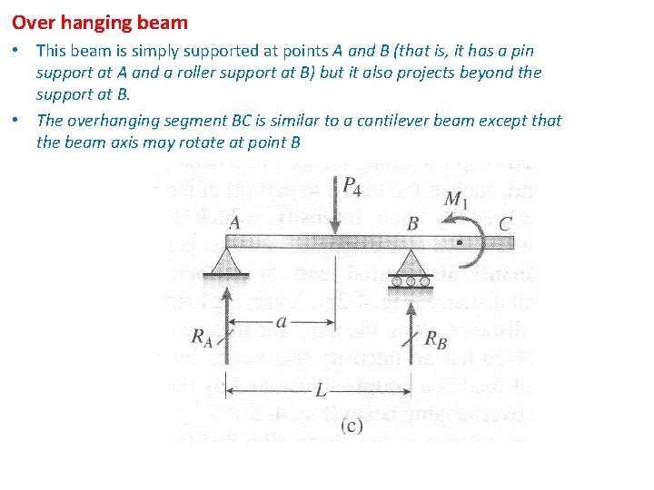
Axial Force, Shear Force and Bending Moment Diagrams for Plane Frames Previous definitions developed for shear forces and bending moments are valid for both beam and frame structures. However, application of these definitions, developed for a horizontal beam, to a frame structure will require some adjustments.
Shear force and bending moment diagram for cantilever beam
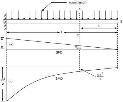
BEAM GURU .COM is a online calculator that generates Bending Moment Diagrams (BMD) and Shear Force Diagrams (SFD), Axial Force Diagrams (AFD) for any statically determinate (most simply supported and cantilever beams) and statically indeterminate beams, frames and trusses. Introduction Notations Relative to "Shear and Moment Diagrams" E = modulus of elasticity, psi I = moment of inertia, in.4 L = span length of the bending member, ft. R = span length of the bending member, in. M = maximum bending moment, in.-lbs. P = total concentrated load, lbs. R = reaction load at bearing point, lbs. V = shear force, lbs. A beam is carrying a uniformly distributed load of w per unit length. Consider the equilibrium of the portion of the beam between sections 1-1 and 2-2. This portion is at a distance of x from left support and is of length dx. F = Shear force at the section 1-1 F + dF = Shear force at the section 2-2, M = Bending moment at the section 1-1,
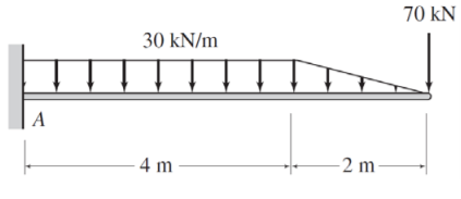
Shear force and bending moment diagram for cantilever beam. PDF_C8_b (Shear Forces and Bending Moments in Beams) Q6: A simply supported beam with a triangularly distributed downward load is shown in Fig. Calculate reaction; draw shear force diagram; find location of V=0; calculate maximum moment, and draw the moment diagram. 6k/ft 9 ft RA = (27k)(9-6)/9= 9k A B F = (0.5x6x9) = 27k x = (2/3)(9) = 6 ft Shear force on cantilever beam is the sum of vertical forces acting on a particular section of a beam. While bending moment is the algebraic sum of moments about the centroidal axis of any selected section of all the loads acting up to the section. Example: Draw shear force and bending moment diagrams of the cantilever beam carrying point loads ... The bending moment and shear force diagrams of the beam are composites of the Vand Mdiagrams of the segments. These diagrams are usually discontinuous, or have discontinuous slopes. At the end-points of the segments due to discontinuities in loading. Sample Problem4.1 The simply supported beam in Fig. (a) carries two concentrated loads. Fulcrumkild shear force bending moment diagram of cantilever beam exles ering intro cantilever beams moments and deflections a cantilever beam is subjected to various lo as shown in figure draw the shear force diagram and bending moment for ethiotutors shear force and bending moment diagram for cantilever beam civil snapshot.
Shear force between any two vertical loads will be constant. And hence the shear force between the two vertical loads will be horizontal. The bending moment at the two ends of the simply supported beam and at the free end of a cantilever will be zero. Shear force and Bending moment Diagram for a Cantilever beam with a Point load at the free end Topic 4.3c: Cantilever Beam - Example 3. Example 3. In this example we have a loaded, cantilever beam, as shown . For this beam we would like to determine expressions for the internal shear forces and bending moments in each section of the beam, and to draw the shear force and bending moment diagrams for the beam. Generally, in the case of cantilevers, the shear force and the bending moment will be maximum at the supports. In this case the shear force is constant throughout the length of the cantilever. Maximum S.F = +W = +12kN Cantilever beam shear force diagram Maximum B.M = -WL = -12 x 4 = -48kN.m Result: Max S.F = +12kN (constant throughout the length) 3.2 - Shear Force & Bending Moment Diagrams What if we sectioned the beam and exposed internal forces and moments. This exposes the internal Normal Force Shear Force Bending Moment ! What if we performed many section at ifferent values Of x, we will be able to plot the internal forces and bending moments, N(x), V(x), M(x) as a function Of position!
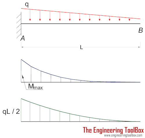
About the Beam Calculator. Welcome to our free online bending moment and shear force diagram calculator which can generate the Reactions, Shear Force Diagrams (SFD) and Bending Moment Diagrams (BMD) of a cantilever beam or simply supported beam. Use this beam span calculator to determine the reactions at the supports, draw the shear and moment ... Shear Force (SF) and Bending Moment (BM) diagrams. Solution: A Cantilever of length l carries a concentrated load W at its free end. Draw the Shear Force (SF) and Bending Moment (BM) diagrams. Consider the forces to the left of a section at a distance x from the free end. Then F = - W and is constant along the whole cantilever i.e. for all ... Shear Force and Bending Moment Diagram Drawing Instructions The ordinates in SFD and BMD diagrams are shear force or bending moment, and the abscissa is the length of the beam. Take a look at the left or right side of the section. On one of the portions, add the forces (including reactions) normal to the beam. Shear Force And Bending Moment Diagram For Simply Supported Beam. Cantilever Beam With Uniformly Varying Load Scientific Diagram. S F D And B M For Cantilever Beam Carrying Uniformly Varying Load U V L On It Span Shear Force Bending Moment Mechanical Ering Unacademy. 4 Bending Moment And Shear Force Diagram.
The shear force and bending moment diagram gives a clear picture in our mind about the variation of SF and BM throughout the entire section of the beam. Further, the determination of value of bending moment as a function of ‘x' becomes very important so as to determine the value of deflection of beam subjected to a given loading where we will use the formula, 2 2 x dy EI M dx. 4.2 Notation ...
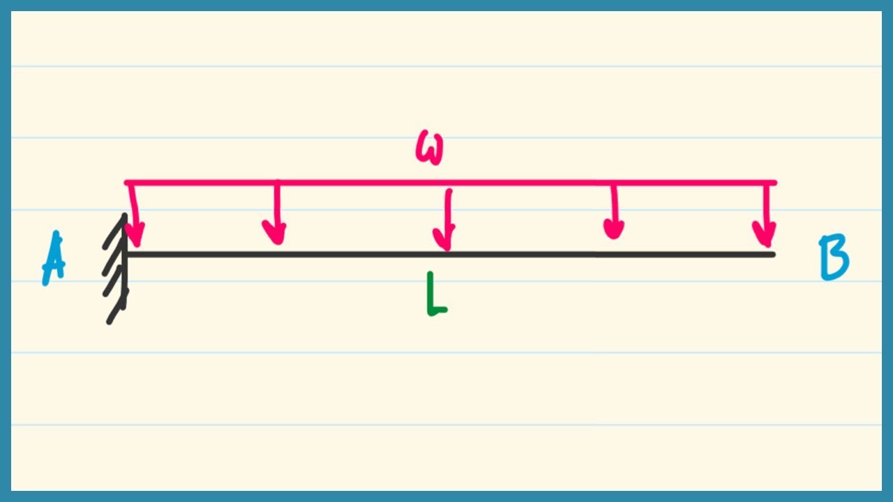
Today we will see here the concept to draw shear force and bending moment diagrams for a cantilever beam with a point load or force acting at free end with the help of this post.Let us consider one beam AB of length L as displayed in following figure.

The bending moment at end of a cantilever beam is module 4 shear force and bending moment diagrams shear force and bending moment diagram extrudesign shear force and bending moment diagram for cantilever beam civil snapshot a cantilever beam ab is subjected to uniformly distributed load as shown in figure ex 3 determine reactions at supports ...

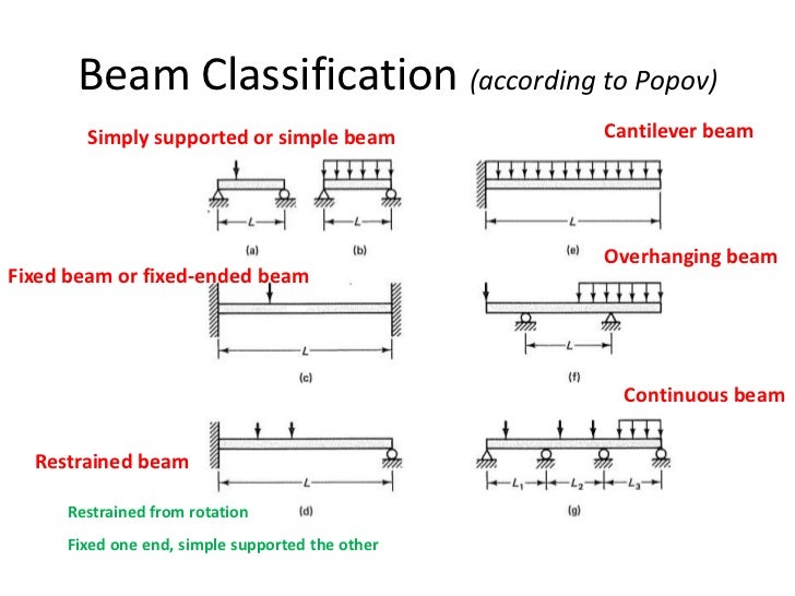
In this article Learn :cantilever beam Bending moment diagram B.M.D. and shear force diagram S.F.D. of a cantilever beam having point load at the end,several point loads,U.D.L. Over Whole Span ,U.D.L. not over the whole span,U.D.L. from support to some distance,U.D.L. Somewhere on the beam,Combination of Point Loads and U.D.L.
Shear Force Bending Moment Diagram Of Cantilever Beam Exles Ering Intro. 5 7 normal and shear stresses bending of beams informit the bending moment is maximum where shear force zero or changes its sign it licable to a cantilever beam also quora maximum stress on a l shaped cantilever beam what is the shear force and bending moment of a ...
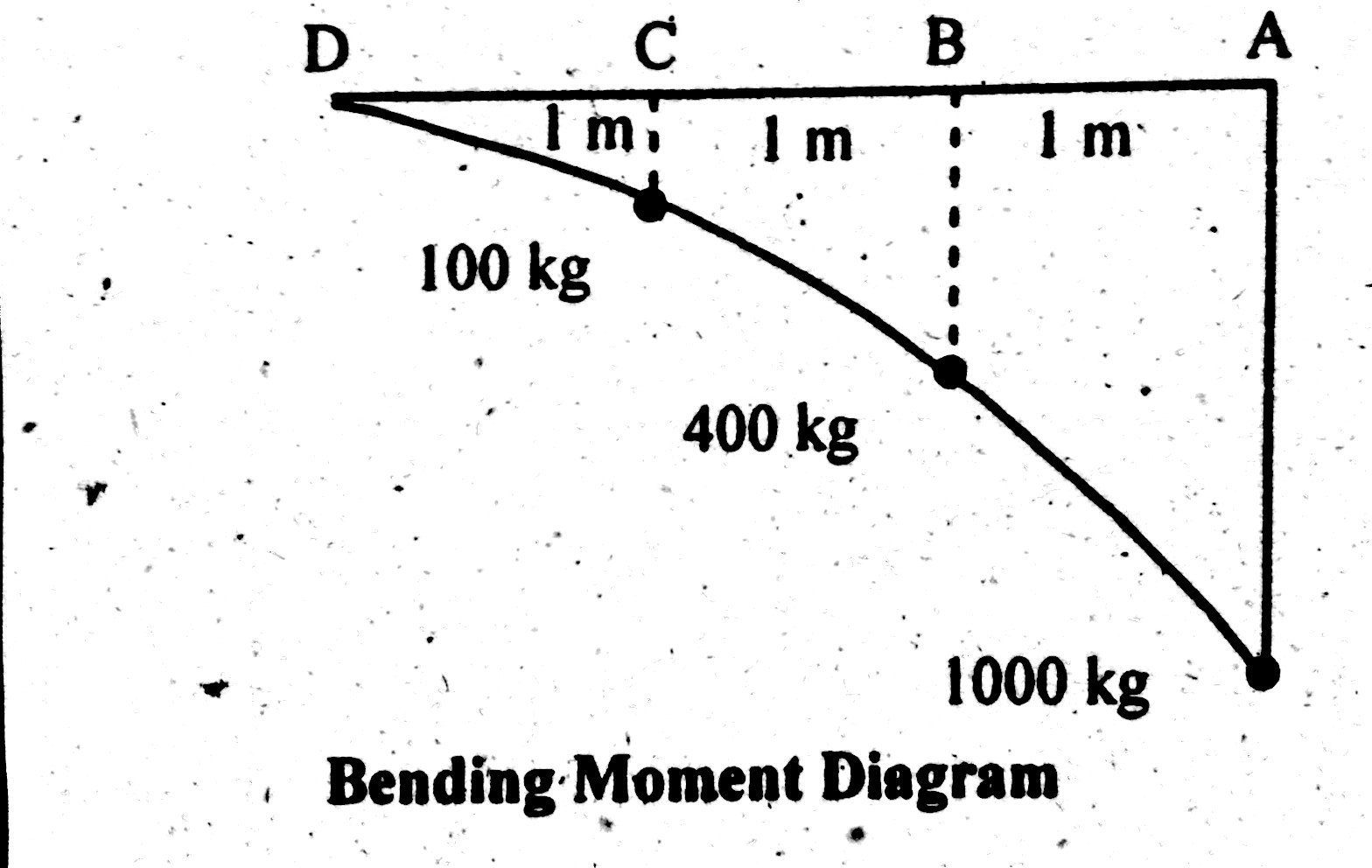
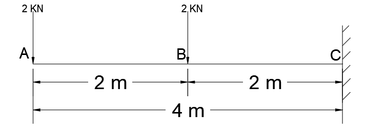
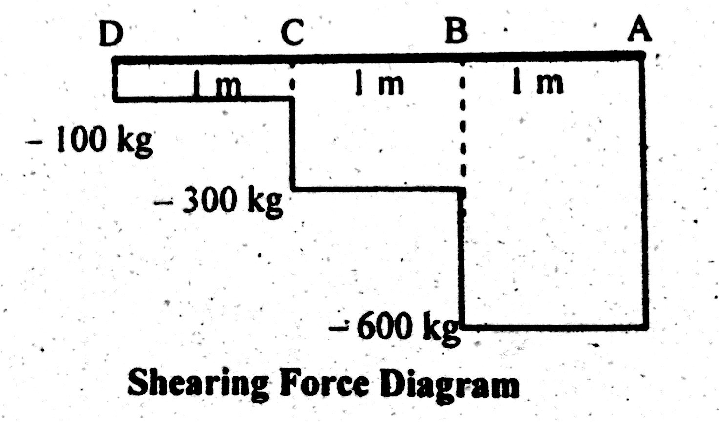
Shear Force and Bending Moment Diagram of Cantilever beam when point load is applied. From the figure we have the value of load at point A and point B. So let’s draws the shear force diagram with the help of these loading. Bending moment at point A is zero. Bending moment at point B= -2*2 = 4 KN-M. Bending moment at point C= -2*4-4*2 = 12 KN-M.

12 Nov 2019 — The shear force diagram (SFD) is drawn in figure 5-1(b) which shows constant value of shear force from A to B and thereafter it increases with a ...

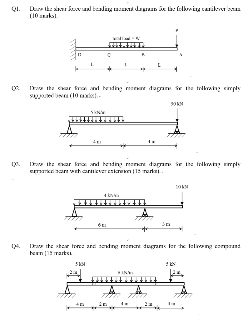
a) Calculate the shear force and bending moment for the beam subjected to a concentrated load as shown in the figure. Then, draw the shear force diagram (SFD) and bending moment diagram (BMD). b) If P = 20 kN and L = 6 m, draw the SFD and BMD for the beam. P kN L/2 L/2 A B EXAMPLE 4

Setting the bending diagrams of beam. Calculate the reactions at the supports of a beam. Bending moment diagram (BMD) Shear force diagram (SFD) Axial force diagram. Invert Diagram of Moment (BMD) - Moment is positive, when tension at the bottom of the beam.
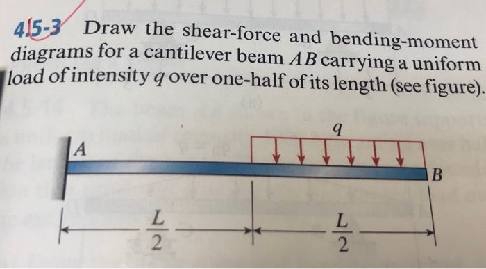
Answer (1 of 3): If this is the structure and load you are describing: The shear force from the free end of the cantilever up to to mid span is 0 and thereafter, from mid span to the support the shear force is P uniformly. The BM from the free end of the cantilever up to the mid span is 0 Ther...

can be visualized, namely, the bending moment and the shear force. It is also understood that the magnitude of bending moment and shear force varies at different cross sections over the beam. The diagram depicting variation of bending moment and shear force over the beam is called bending moment diagram [BMD] and shear force diagram [SFD].

A beam is carrying a uniformly distributed load of w per unit length. Consider the equilibrium of the portion of the beam between sections 1-1 and 2-2. This portion is at a distance of x from left support and is of length dx. F = Shear force at the section 1-1 F + dF = Shear force at the section 2-2, M = Bending moment at the section 1-1,
Introduction Notations Relative to "Shear and Moment Diagrams" E = modulus of elasticity, psi I = moment of inertia, in.4 L = span length of the bending member, ft. R = span length of the bending member, in. M = maximum bending moment, in.-lbs. P = total concentrated load, lbs. R = reaction load at bearing point, lbs. V = shear force, lbs.

BEAM GURU .COM is a online calculator that generates Bending Moment Diagrams (BMD) and Shear Force Diagrams (SFD), Axial Force Diagrams (AFD) for any statically determinate (most simply supported and cantilever beams) and statically indeterminate beams, frames and trusses.


0 Response to "40 shear force and bending moment diagram for cantilever beam"
Post a Comment