40 pure iron phase diagram
A. Phase Diagrams 1. Iron-Copper System The iron-copper phase diagram, taken from Hansen,3 is presented in Figure 1. Hansen3 also gives a thorough review of the work done on the system up to 1957. A review of more recent work, up to 1963 was done by . Elliott~ The most recent version of the phase diagram
Derivative works of this file: Pure iron phase diagram (EN).png This is a retouched picture , which means that it has been digitally altered from its original version. The original can be viewed here: Diagramma di fase del ferro puro.svg : .
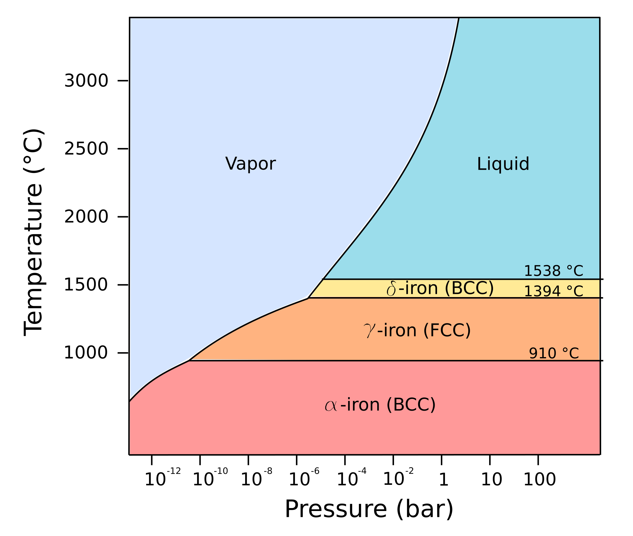
Pure iron has many allotropic forms, which switch between one -another depending on pressure and temperature. The conventional diagram does not extend to suf...

Pure iron phase diagram
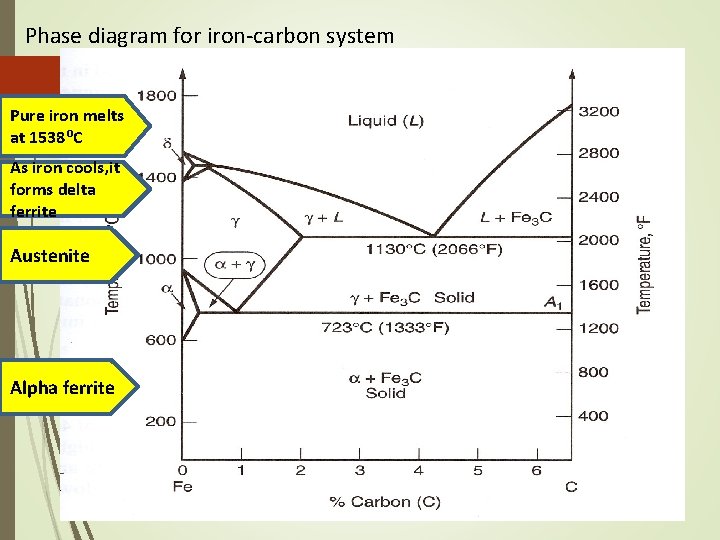
It will form a solid solution with α, γ, and δ phases of iron. Types of Ferrous Alloys on the Phase Diagram. The weight percentage scale on the X-axis of the iron carbon phase diagram goes from 0% up to 6.67% Carbon. Up to a maximum carbon content of 0.008% weight of Carbon, the metal is simply called iron or pure iron.
Another interesting diagram, shown in Figure 2.15, is that for the iron-carbon system, which gives rise to the group of alloys known as steels.The polymorphic changes which take place in pure iron result in the formation of three different single-phase fields in iron-rich alloys, namely, α-iron, or ferrite (bcc), γ-iron, or austenite (fcc) and δ-iron (bcc).
The phased diagram includes four solid phases α Ferrite ..The solid solution of carbon in iron. At 0% C this is pure iron. BCC crystal structure. The maximum solubility of carbon in iron is 0,02% at 723oC. The carbon atoms are located in the crystal interstices. Austenite The solid solution of carbon in γ iron is called austenite .
Pure iron phase diagram.
From Wikipedia, the free encyclopedia Low-pressure phase diagram of pure iron. BCC is body centered cubic and FCC is face-centered cubic. Iron-carbon eutectic phase diagram, showing various forms of Fe x C y substances. Iron allotropes, showing the differences in lattice structure.
A phase diagram in which the components display unlimited solid solubility. Chapter 10: Solid Solutions and Phase Equilibrium ... • Pure iron when heated experiences 2 changes in crystal structure before it melts. • At room temperature the stable form, ferrite ( iron) has a BCC crystal
At higher temperatures, austenitic iron changes to a high-temperature bcc structure, referred to as d iron. Similar phase changes occur during cooling.Underequilibriumconditions,thesolid-ification of pure iron from the liquid occurs at 1540 C (2800 F) and forms d iron. Delta iron is then stable on further cooling until it reaches
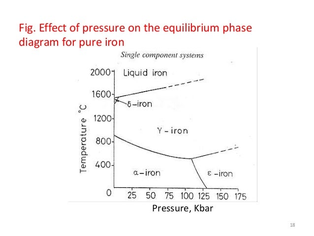
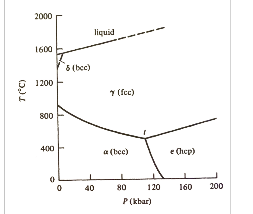
Pure iron at one atmospheric pressure, as we saw, exists as alpha (BCC) and gamma (FCC) iron, but changes to a new crystalline phase HCP (ԑ) at pressures above 100 k bar with a = 2.95 A°, c = 3.93 A°, and c/a = 1.61. Polymorphic change can be categorised in two classes based on the reversibility of the change as:
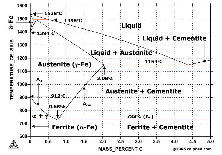
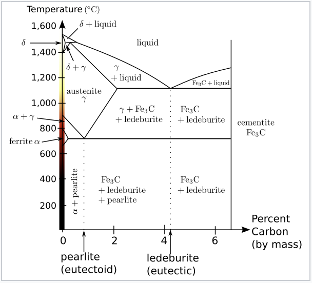
The Iron carbon equilibrium diagram (also called the iron carbon phase diagram) is a graphic representation of the respective microstructure states of the alloy iron - carbon (Fe-C) depending on temperature and carbon content. The iron carbon phase diagram is commonly used to fully understand the various phases of steel and cast iron.
On this channel you can get education and knowledge for general issues and topics
The Lehrer diagram, which describes the phase stabilities in pure iron under different nitriding potentials and temperatures, is inherently designed to provide the gas nitriding process parameters. This diagram was developed by experiments in 1930 4 [10] and there is no experimentally determined Lehrer diagrams available for alloy steels.
Abstract As the main constituent of planetary cores, pure iron phase diagram under high pressure and temperature is of fundamental importance in geophysics and planetary science. However, previously reported iron-melting curves show large discrepancies (up to 1000 K at the Earth's core-mantle boundary,
The Iron-Carbon Phase Diagram The phase diagrams are very important tools in the study of alloys for solutions of many practical problems in metallurgy. These diagrams define the regions of the stability of a phase which can exist in an alloy system under the condition of constant atmospheric pressure.
A study of the microstructure of all steels usually starts with the metastable iron-carbon (Fe-C) binary phase diagram (Figure 1). It provides an invaluable foundation on which to build knowledge of both carbon steels and alloy steels, as well as a number of various heat treatments they are usually subjected to (hardening, annealing, etc).
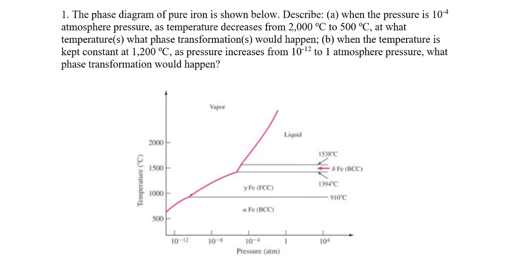
As shown in figure by left axes, pure iron upon heating exhibits two allotropic changes. One involves α-ferrite of BCC crystal structure transforming to FCC austenite, γ- iron, at 910C. At 1400°C, austenite changes to BCC phase known as δ -ferrite, which finally melts at 1536°C.
Iron - Carbon Phase Diagram In their simplest form, steels are alloys of Iron (Fe) and Carbon (C). The study of the constitution and structure of iron and steel start with the iron carbon phase diagram. It is also the basic understanding of the heat treatment of steels. Iron Carbon phase diagram
Allotropes of iron - wikipedia
Sucrose/Water Phase Diagram Pure Sugar Temperature (°C) 0 20 40 60 80 100 Co =Composition (wt% sugar) L (liquid solution i.e., syrup) Solubility Limit L (liquid) + S (solid 20 sugar) 40 60 80 100 Pure Water Adapted from Fig. 9.1, Callister 7e. Chapter 9 - 3 • Components :

The iron-carbon alloys and fe-c phase diagram - mechanicalbase
Cooling curve for pure iron 5. Definition of structures Various phases that appear on the Iron-Carbon equilibrium phase diagram are as under: •Austenite •Ferrite •Pearlite •Cementite •Martensite* •Ledeburite 6. Unit Cells of Various Metals FIGURE - The unit cell for (a) austentite, (b) ferrite, and (c) martensite.

A menagerie of pure component phase diagrams
Carbon Steels and the Iron-Carbon Phase Diagram Steels are alloys having elements of iron (Fe) and carbon (C). C gets dissolved in Fe during the production of steels. Pure Fe melts at a temperature of 1540 deg C, and at this temperature, C readily dissolves into the liquid iron, generating a liquid solution.
Solved 1. the phase diagram of pure iron is shown below ...
M. Strangwood, in Phase Transformations in Steels: Fundamentals and Diffusion-Controlled Transformations, 2012 6.3.2 Pure iron. For pure iron, with no partition required, there is no need for long-range diffusion in the parent austenite phase and the rate of transformation depends on the mobility of the α/γ interface. The transformation rate is therefore expected to be rapid, although ...

1. experimental pressure-temperature phase diagram of pure ...
A phase diagrams is a type of graph used to show the equilibrium conditions between the thermodynamically-distinct phases; or to show what phases are present in the material system at various T, p, and compositions ... Cooling curve for pure iron @ 1atm

Iron-carbon phase diagram under atmospheric pressure. this ...
Therefore, the phase diagram of the iron/carbon alloy system is somewhat more complex. In order to understand the microstructural processes inside a steel, it makes sense to first take a closer look at the microstructure formation of pure iron. For this reason, the cooling curve of iron is discussed in more detail in the following section. ...
Iron phase diagram - roy mech
Review Fe-C phase diagram • 2 important points-Eutectoid (B): γ⇒α+Fe 3C-Eutectic (A): L ⇒γ+Fe 3C Fe 3 C (cementite) 1600 1400 1200 1000 800 600 400 0 12 3 4 5 66.7 L γ (austenite) γ+L γ+Fe 3C α+Fe 3C α + γ L+Fe 3C δ (Fe) C o, wt% C 1148°C T(°C) α 727°C = Teutectoid A R S 4.30 Result: Pearlite = alternating layers of αand Fe ...

The iron carbon phase diagram
The moderate P-T phase diagram of Fe is reviewed in Swartzendruber [18] and it is reported in Fig. 1.2. At room temperature and atmospheric pres-sure, pure iron is stable in the body centered cubic - bcc - ( ) phase. This phase is ferromagnetic, below the Curie temperature (1043 K) [19] before

Gate metallurgical engineering: iron-iron carbide phase diagram
Low-pressure phase diagram of pure iron The first three forms are observed at ordinary pressures. As molten iron cools past its freezing point of 1538 °C, it crystallizes into its δ allotrope, which has a body-centered cubic (bcc) crystal structure.
![Iron-Carbon Phase Diagram Explained [with Graphs]](https://fractory.com/wp-content/uploads/2020/03/Iron-carbon-phase-diagram-explained.jpg)
Iron-carbon phase diagram explained [with graphs]
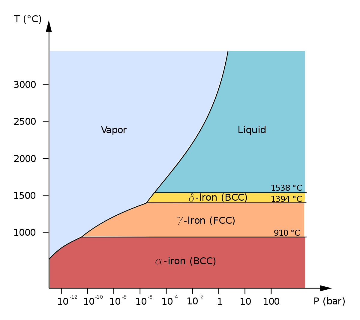
The following figure is the phase diagram of pure iron, which indicates the equilibrium phase (s) of iron for various conditions of temperature and pressure. α-Fe (alpha iron) denotes a BCC form of iron, whereas γ-Fe (gamma iron) denotes an FCC form of iron. Ambient pressure of 1 atm is approximately 1.01 bar. Therefore, ambient pressure.

Hexaferrum - wikipedia
Cementite or iron carbide, is very hard, brittle intermetallic compound of iron & carbon, as Fe 3 C, contains 6.67 % C. It is the hardest structure that appears on the diagram, exact melting point unknown. Its crystal structure is orthorhombic. It is has low tensile strength (approx. 5,000 psi), but high compressive strength.

Cast iron; 9.5.1 general remarks

Michael poh's personal homepage

Tpce mech books: iron carbon phase diagram or equilibrium diagram
Iron phase diagram - roy mech

Chapter 9 phase diagrams. - ppt video online download

Delta iron - an overview | sciencedirect topics
Phase diagrams [9]
Phase transformation lecture equilibrium, phase diagram
Tikalon blog by dev gualtieri

Schematic of the phase diagram of pure iron at high pressures ...
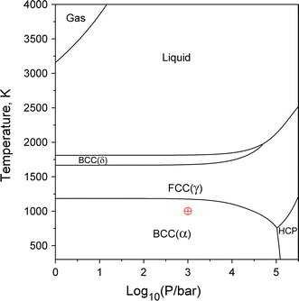
Figure 2 | phase diagrams: the beginning of wisdom | springerlink
Phase diagram iron carbon | metallurgy for dummies

The gibbs free energy difference between and phases of pure ...
Solved d question 5 5 pts the following figure is the phase ...

Phase diagram of pure iron (हिन्दी )
![Solved 5. [05] CO2 In the pure iron pressure-temperature ...](https://media.cheggcdn.com/study/40f/40ff4825-88a2-4f3f-8f37-94ac1e6793b3/image)
Solved 5. [05] co2 in the pure iron pressure-temperature ...

Phase diagrams–equilibrium microstructural development - ppt ...
Iron-iron carbide phase diagram example
Chapter 5 metal alloys heat treatment phase diagram

Phase equilibrium part 6 chemistry engineering department ...
Solved the following figure is the phase diagram of pure ...
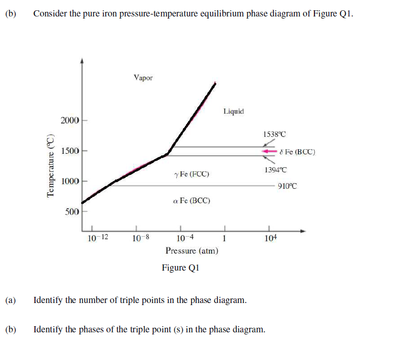
Solved (b) consider the pure iron pressure-temperature ...
7.4: iron and steel - chemistry libretexts

A phase diagram for fe-4 wt%si in comparison to that of pure ...

Pure iron - the phase diagram - terapascal pressures, 20000 k

Gate & ese - phase diagram - 2 (cooling curve of pure iron ...
Berkas:pure iron phase diagram (en).svg - wikipedia bahasa ...

Fig. s1. the calculated phase diagram of pure iron along with ...
0 Response to "40 pure iron phase diagram"
Post a Comment