39 rlc circuit phasor diagram
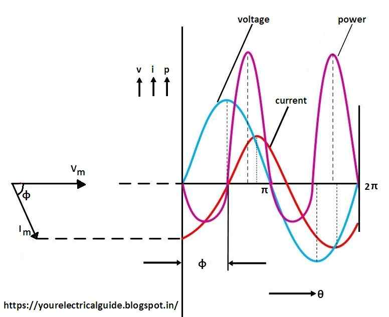
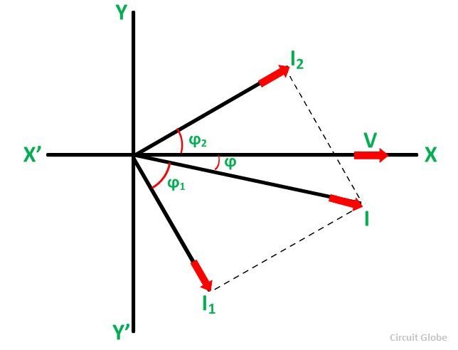
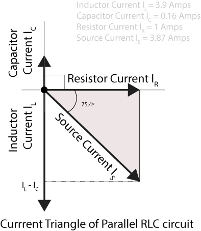
Phasor diagram of parallel RLC circuit, I R is the current flowing in the resistor, R in amps. I C is the current flowing in the capacitor, C in amps. I L is the current flowing in the inductor, L in amps. I s is the supply current in amps. In the parallel RLC circuit, all the components are connected in parallel; so the voltage across each ... (b) Phasor diagram for the resistive circuit. The behavior of IR (t)and can also be represented with a phasor diagram, as shown in Figure 12.2.2(b). A phasor is a rotating vector having the following properties: VR (t) (i) length: the length corresponds to the amplitude. (ii) angular speed: the vector rotates counterclockwise with an angular ...
Chapter 12.3 - Phasor Diagram of Series RLC Circuit ... frequency f of the applied signal in relation to the frequency of resonance f0. Three different cases may ...

Rlc circuit phasor diagram
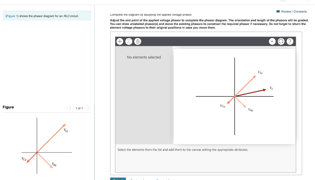
You can draw unlabeled phasor(s) and move the existing phasors to; Question: (Figure 1) shows the phasor diagram for an RLC circuit. Figure 1 of 1 VLE VCP VRP Complete the diagram by adjusting the applied voltage phasor. Adjust the end point of the applied voltage phasor to complete the phasor diagram. Phasor diagram for series RLC circuit Example: for the circuit shown in figure (a), draw the phasor circuit , impedance diagram and voltages phasor diagram. V=50∟0, so the phasor circuit is shown in figure (b). Z T =Z R +Z L +Z C =3Ω+7Ω-j3Ω =3+j4= 5∟53.13o. Impedance diagram is shown in figure (c). V R =IZ R Vectors, Phasors and Phasor Diagrams ONLY apply to sinusoidal AC alternating quantities. A Phasor Diagram can be used to represent two or more stationary sinusoidal quantities at any instant in time. Generally the reference phasor is drawn along the horizontal axis and at that instant in time the other phasors are drawn.
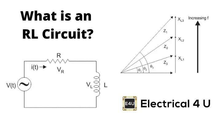
Rlc circuit phasor diagram. An RLC circuit (also known as a resonant circuit, tuned circuit, or LCR circuit) is an electrical circuit consisting of a resistor (R), an inductor (L), and a capacitor (C), connected in series or in parallel. This configuration forms a harmonic oscillator. 2. The phasor diagram for the RLC series circuit of . At any instant, the voltage across the RLC combination is the emf of the source. Since a component of a sum of vectors is the sum of the components of the individual vectors—for example, —the projection of the vector sum of phasors onto the vertical axis is the sum of the vertical ... Network Theory: Phasor Diagram of Parallel RLC Circuit Topics discussed:1) Phasor diagram of Parallel RLC circuit.2) Current triangle of Parallel RLC circuit... An example of series RLC circuit and respective phasor diagram for a specific ω . ... circuits with phasors to analyze single frequency linear AC ...
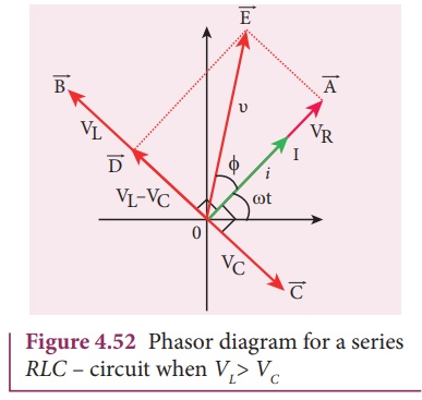
Phasor diagram RLC ... So I have to do a phasor diagrams for this 4 circuits. ... RLC - Phasor diagram The nature of the phasor diagram of a series RLC circuit depends on the frequency f of the applied signal in relation to the frequency of resonance f0. Three different cases may be considered: (i) f = fr, (ii) f < fr, and (iii) f > fr. with f = f0, the reactance X L of inductor L equals the reactance of capacitor C. The phasor diagram for a series RLC circuit is produced by combining together the three individual phasors above and adding these voltages vectorially. Phasor Diagram of Inductive Series RLC Circuit We normally take the direction of the circuit current as the reference axis of the diagram. The voltage drop across the resistance will have the same phase as that circuit current. The voltage drop across the inductive reactance will be perpendicularly upward on the current axis.
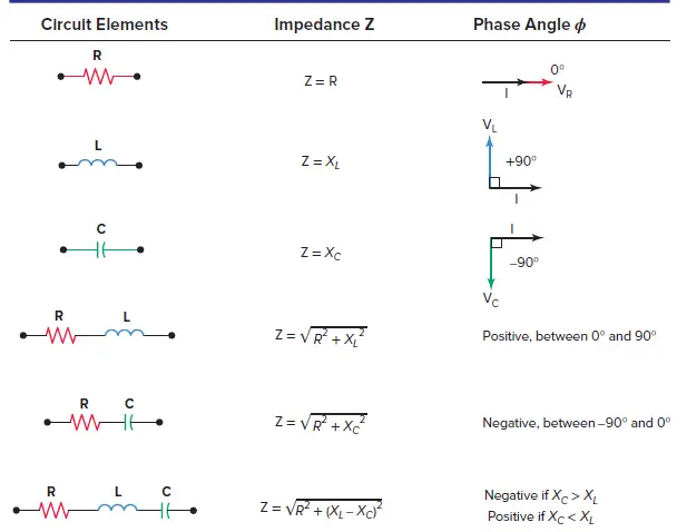
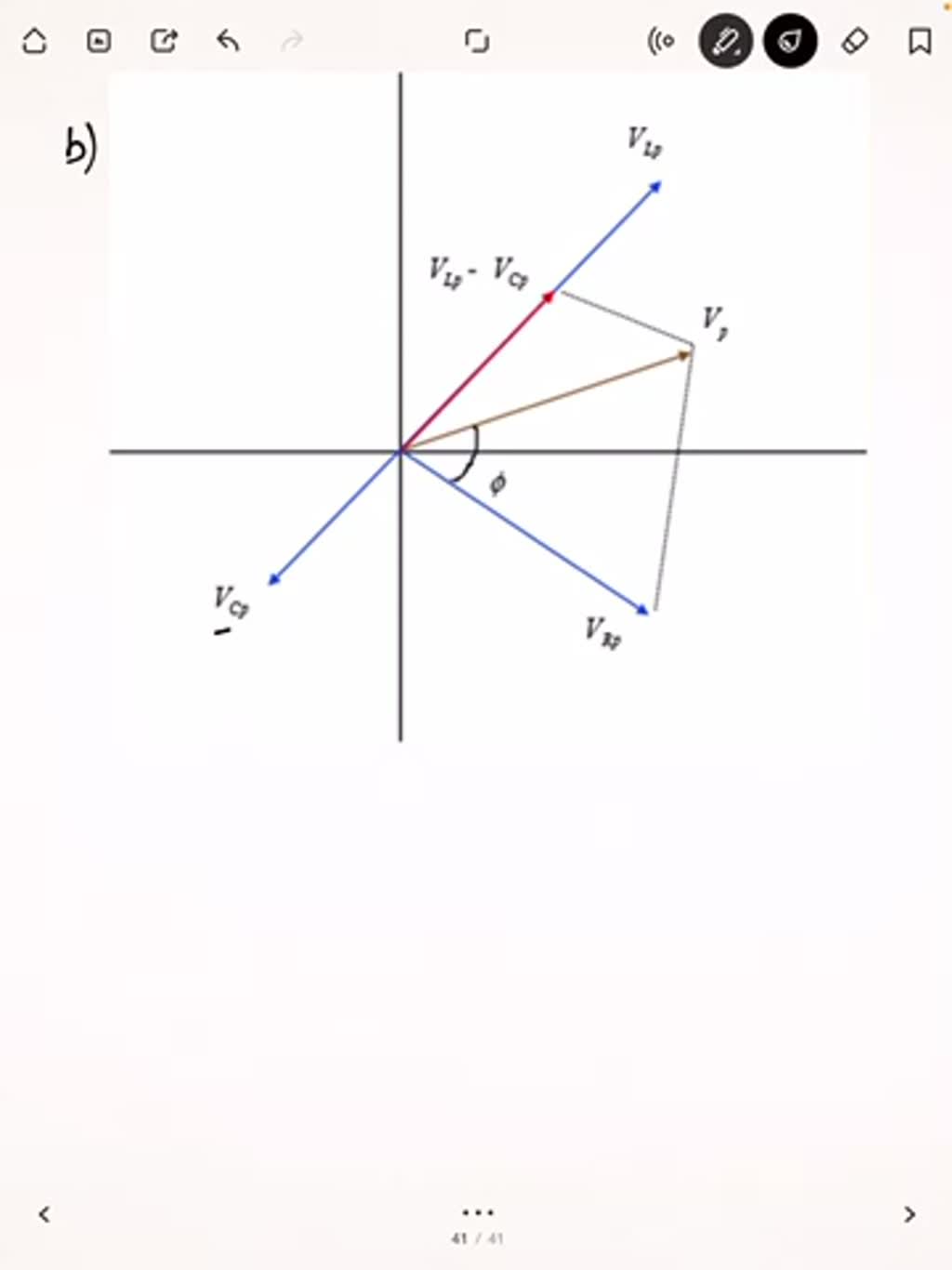
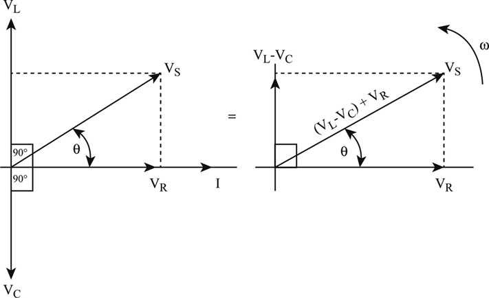
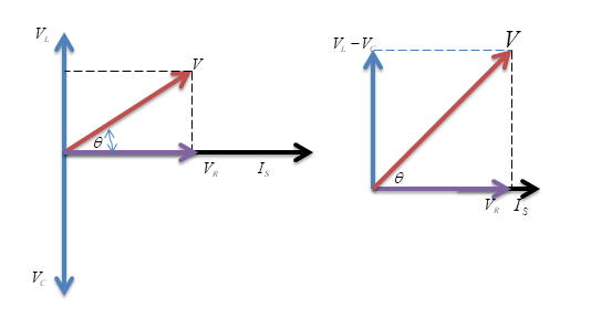
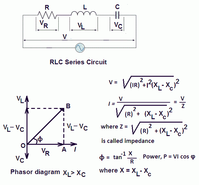
RLC phasor diagram. it is a series RLC circuit. How about the phasor diagram of E,VR,VL,VC? I'm not completely sure about this, but I think you draw 3 arrows head-to tail. The first arrow, V (R) starts at the origin of a cartesian graph, is 10 units long, and is at an angle 53.10 deg below the X-axis. The next V (L) arrow is 20 units long, is ... The phasor diagram of the RLC series circuit when the circuit is acting as an inductive circuit that means (V L >V C) is shown below and if (V L < V C) the circuit will behave as a capacitive circuit. Steps to draw the Phasor Diagram of the RLC Series Circuit Take current I as the reference as shown in the figure above To draw the phasor diagram of RLC series circuit, the current I (RMS value) is taken as the reference vector. The voltages across three components are ... The phasor diagram for a series RLC circuit for capacitive (left), inductive (center) and pure resistive (right) impedance. The voltage vectors on the diagram produce a rectangular voltage triangle with a hypotenuse V T, vertical leg V L -V C and horizontal leg V R.
RLC Series circuit As described above the overall phasor will look like below: Phasor diagram of current Vs voltage for resistor, inductor and capacitor for RLC series circuit From the above phasor diagram we know that, V 2 V 2 = (V R)2 + (V L - V c)2 ( V R) 2 + ( V L - V c) 2 —- (1)

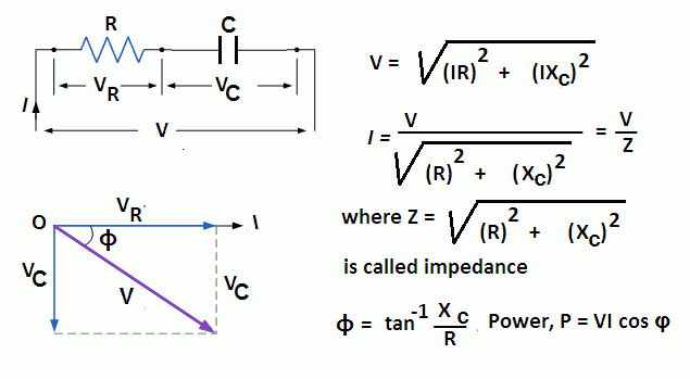
For the given circuit diagram calculate the RLC series circuit impedance, current, voltage across each component, and power factor. Also draw the phasor diagram of current and voltage, impedance triangle, and voltage triangle. First of all, let me calculate the total impedance with the following formula Resistance: $R=12\Omega$
Phasor diagram for a series RLC circuit · Consider a circuit in which R, L, and C are connected in series with each other across ac supply as ...
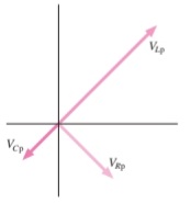
Figure 2 Voltage vector (phasor) diagram for a series RLC circuit. The circuit's phase angle theta (θ) is always the angle that separates the circuit's current and the applied voltage source, as summarized in Table 1.
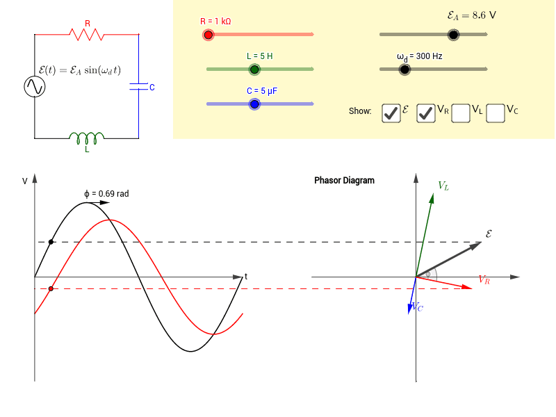
This Demonstration shows a phasor diagram in an AC series RLC circuit. The circuit consists of a resistor with resistance , an inductor with inductance , and a capacitor with capacitance . The current in an RLC series circuit is determined by the differential equation [more] Contributed by: Anping Zeng (July 2011)

Phasor diagram, Circuit Diagram, Formula | Alternating Current (AC) - Resonance in series RLC Circuit | 12th Physics : Electromagnetic Induction and Alternating Current Posted On : 24.03.2019 08:39 pm

In the article sinusoidal response of series RLC circuit, we will discuss about RLC series circuit, it ’ s phasor diagram for leading and ...
Network Theory: Phasor Diagram of Series RLC Circuit Topics discussed:1) Phasor diagram of series RLC circuit.2) Voltage triangle of series RLC circuit.3) Im...
The phasor diagram for the RLC series circuit shows the main features. Note that the phase angle, the difference in phase between the voltage and the current in an AC circuit, is the phase angle associated with the impedanceZ of the circuit. AC behavior of inductor AC behavior of capacitor Index AC circuit concepts

What does the voltage phasor diagram look like when the voltage across capacitor is at its positive maximum? IX c IR e IX L IX c IR IX e L Electricity & Magnetism Lecture 20, Slide 24 A driven RLC circuit is represented by the phasor diagram below. When the voltage across the capacitor is at its positive maximum, V C = +V C,max, what

13+ Phasor Diagram Parallel Rlc Circuit. A rlc circuit as the name implies will consist of a resistor, capacitor and inductor connected in series or parallel. The rlc circuit is analogous to the wheel of a car driven over a corrugated road ( figure 15.15 ). These circuit has the ability to provide a resonant frequency signal as shown in the below.

PHY2054: Chapter 21 2 Voltage and Current in RLC Circuits ÎAC emf source: "driving frequency" f ÎIf circuit contains only R + emf source, current is simple ÎIf L and/or C present, current is notin phase with emf ÎZ, φshown later sin()m iI t I mm Z ε =−=ωφ ε=εω m sin t ω=2πf sin current amplitude() m iI tI mm R R ε ε == =ω
We recall from the previous tutorial about series RLC circuits that the voltage across a series combination is the phasor sum of V R, V L and V C. Then if at resonance the two reactances are equal and cancelling, the two voltages representing V L and V C must also be opposite and equal in value thereby cancelling each other out because with ...
A series RC circuit is driven by emf ε. Which of the following could be an appropriate phasor diagram? Clicker problem (a) (c)(b) VR VL VC εm VR VC εm ~ 2A VR εm VC • The phasor diagram for the driven series RLC circuit always has the voltage across the capacitor lagging the current by 90 °. The vector sum
For drawing the phasor diagram of parallel RLC circuit, voltage is taken as reference because voltage across each element remains the same and all the other currents i.e I R, I C, I L are drawn relative to this voltage vector. We know that in case of resistor, voltage and current are in same phase; so draw current vector I R in same phase and direction to voltage.
Step Response RLC Circuit ... PWM Motor Reversible Control Circuit Diagram ... Phasor Diagram RLC Circuit

Phasor Diagram of Series RLC Circuit The phasor diagram of series RLC circuit is drawn by combining the phasor diagram of resistor, inductor and capacitor. Before doing so, one should understand the relationship between voltage and current in case of resistor, capacitor and inductor. Resistor
What Is Rlc Series Circuit Phasor Diagram Impedance Triangle Globe. The phasor diagram shows the phase difference between voltage an current. The LCR circuit analysis can be understood better in terms of phasors.

In this video, Phasor diagram representation of voltage and current for Series RC, RL and RLC circuit has been explained and the examples based on this phaso...
... Rlc Circuit Resonant Circuit Following Differential ... Elements Of Ac Circuits The Series Rlc Circuit and Phasor Diagram Of Series Rlc Circuit The
Vectors, Phasors and Phasor Diagrams ONLY apply to sinusoidal AC alternating quantities. A Phasor Diagram can be used to represent two or more stationary sinusoidal quantities at any instant in time. Generally the reference phasor is drawn along the horizontal axis and at that instant in time the other phasors are drawn.
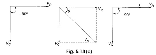
Phasor diagram for series RLC circuit Example: for the circuit shown in figure (a), draw the phasor circuit , impedance diagram and voltages phasor diagram. V=50∟0, so the phasor circuit is shown in figure (b). Z T =Z R +Z L +Z C =3Ω+7Ω-j3Ω =3+j4= 5∟53.13o. Impedance diagram is shown in figure (c). V R =IZ R
You can draw unlabeled phasor(s) and move the existing phasors to; Question: (Figure 1) shows the phasor diagram for an RLC circuit. Figure 1 of 1 VLE VCP VRP Complete the diagram by adjusting the applied voltage phasor. Adjust the end point of the applied voltage phasor to complete the phasor diagram.


0 Response to "39 rlc circuit phasor diagram"
Post a Comment