38 magnetic switch wiring diagram
Diagram #1: Wiring a Piezo to a Jack . This diagram shows about the most basic wiring setup you can get: a single piezo transducer wired directly to a mono (two pole) jack. This is the setup that many first-time CBG builders use when looking to be able to plug their build into an amp. Typical Wiring Diagram Line diagrams show circuits of the operation of the. Eaton magnetic starter wiring diagram. Basic wiring for motor control 36326 ads8 brochure eaton cutler hammer magnetic switch. Eaton motor starter wiring diagram 40 Awesome Square D Model 6 Mcc Wiring Diagram motor control center aftermarket buckets. January 3 2021 1.
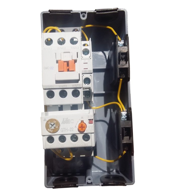
The Murphy Tattletale Magnetic Switch 12V for High Vibration 518E-12 is the nerve center that translates Swichgage contact operations into decisions and operate the alarm or shutdown device. It allows for Swichgage and/or N.C. contacts to be wired "Closed Loop" (in series).

Magnetic switch wiring diagram
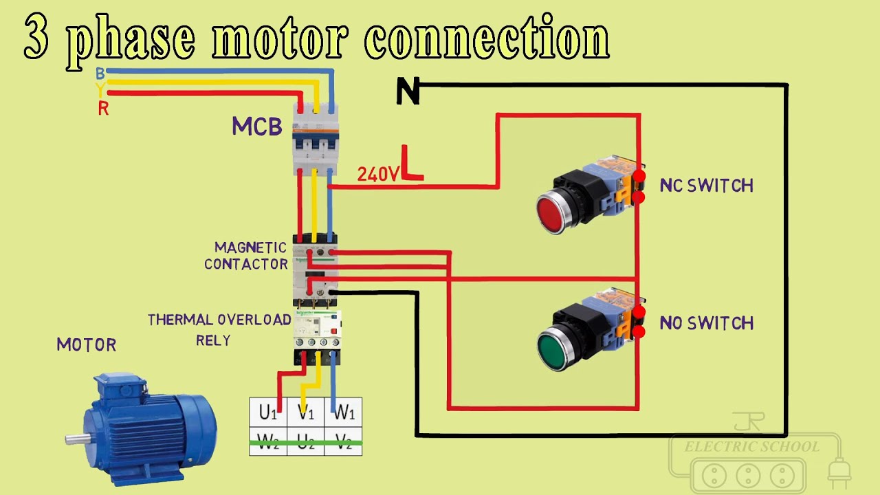
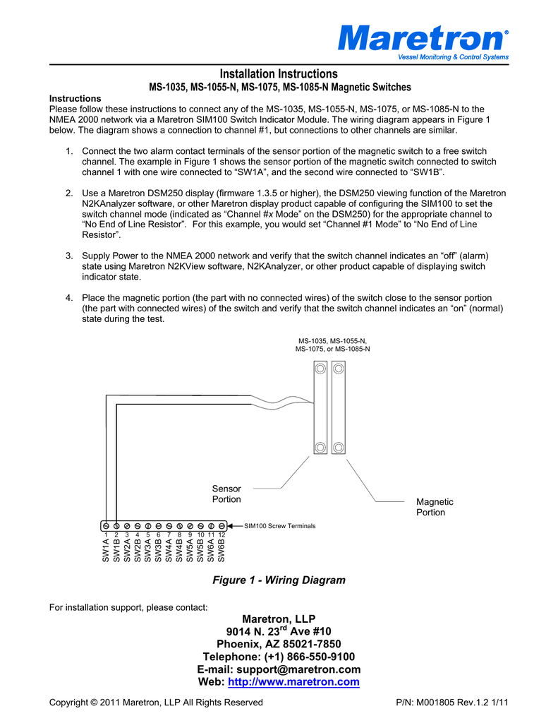
The wiring diagram appears in Figure 1 below. The diagram shows a connection to channel #1, but connections to other channels are similar. Eaton magnetic motor starter 7 5 hp 230 volt three phase air compressor parts factory. Each component should be placed and connected with other parts in specific way. The new one is a weg cwm50. Assortment of air compressor motor starter wiring diagram. The above wiring diagram assumes your magnetic starter has a 240v coil. A typical starter solenoid has one small connector for the starter control wire the white connector in the photo and two large terminals. 240 volt 1 phase motors should use a 2 pole starter. In this automatic changeover switch for generator circuit diagram the CONTACTORs of the generator are indicated KG and KM.
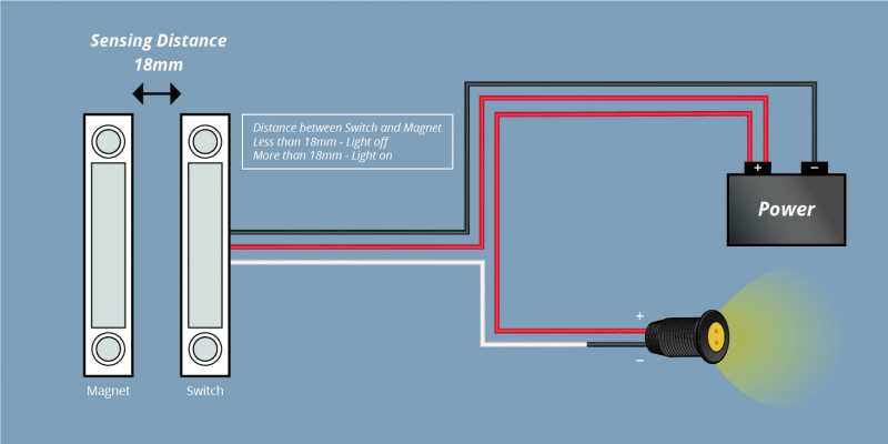
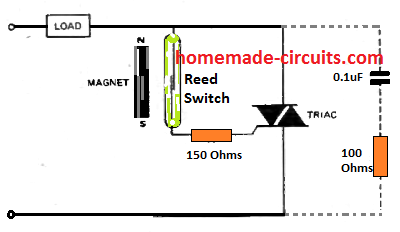
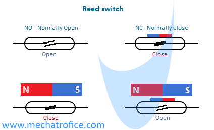
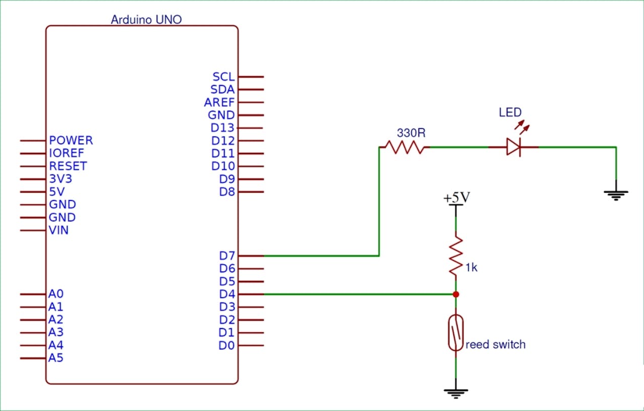
Magnetic switch wiring diagram. Magnetic Reed Switch Wiring Diagram. Note: Posi-Tap? connectors, terminal ... to connect the wiring cable to sensor wires. Security 1. Battery 1 (+).1 page Phase magnetic switch wiring diagram siemens furnas contactors motor practical machinist largest l t starter circuit full controls catalog water pressure 3 single and 5 hp esp100 the data sheet pdf electrical diagrams trouble a help heavy duty starters ws7 2301p air compressor 220 shefalitayal 14hsj32ba garage journal fs mag 42df35af square d ... This product is a reed switch type Auto switch of direct mounting specification. ... 2) Do not carry a cylinder (actuator) by the auto switch lead wires.2 pages A switch with one magnetic reed and one non-magnetic one. US Patent 3,348,175: Normally closed reed switch by Anthony J. Wilkis, October 17, 1967. Describes various ways of making a normally closed switch. Videos. Introduction to Reed Switches, Magnets and Magnetic Fields by Stephen Day. Quite a neat summary of how reed switches are used in ...
Volume 10 Tab 4. Ge Solutions Cr460 Lighting Contactor Series User Manual Page 4. Selecting Effective Lighting Control White Paper. Wiring Diagram Asco 917 918 Remote Control Switch N O C 383825 Instruction Sheet Power Technologies. Asco 918 Lighting Contactors Drawing Wiring Diagrams. C30cn Lighting Contactor Series. Sea Ray Boat Wiring Diagram - sea ray boat wiring diagram, Every electrical structure consists of various unique pieces. Each part ought to be placed and connected with other parts in specific manner. If not, the arrangement won't work as it ought to be. Magnetic Contactor Wiring Diagram - Data Wiring Diagram Schematic - Contactor Wiring Diagram. Wiring diagram also gives beneficial recommendations for projects that might demand some extra equipment. This book even contains recommendations for extra supplies that you may require in order to complete your projects. Typical Wiring Tech Sheet For Magnetic Switches And Lighted Rocker Switch Wiring Diagram 120V - 120v illuminated rocker switch wiring diagram, lighted rocker switch wiring diagram 120v, Every electric arrangement is composed of various diverse parts. Each part should be placed and linked to different parts in particular manner.
Solenoid switches are used to control large current circuits with a low current switch. 2 Way Switch Wiring Diagram : Installing new 10 Amp Double 2 Way Lightswitch | DIYnot Forums. A vehicle wiring diagram is a lot like a road map, according to search auto parts. Hi i would like to know how this switch should be wired up. Oct 13, 2017 — Currently my saw is hardwired to a plug and controlled via a breaker, so yeah, this switch is very well needed. There is a tiny schematic in the ... Wiring Diagram For Motor Starter 3 Phase Controller Failure Relay Electrical Pleasing Thre Electrical Circuit Diagram Electrical Wiring Basic Electrical Wiring. Magnetic Contactor Wiring Diagram Pdf Electrical Circuit Diagram Electrical Wiring Basic Electrical Wiring. Dol Starter Connection Single Phase Motor Connection With Magnetic C In 2021 ... Wiring Diagram For Double Light Switch Uk. 2000 Club Car 48 Volt Wiring Diagram. 4 To 1 Multiplexer Circuit Diagram And Truth Table. Pull Cord Switch Wiring Diagram Uk. Logic Circuit Generator From Boolean Expression. Hyundai Car Radio Stereo Audio Wiring Diagram. Wiring. Related Posts.
Stator is used to generate magnetic field. 14+ 3 Phase Forward Reverse Switch Wiring Diagram. As the diagram below shows, only one pickup is hooked up to the phase switch. Power & control wiring trending. 3 phase forward reverse switch wiring diagram. I drew this up on a sheet of paper and it is easy to figure out. Source: www ...
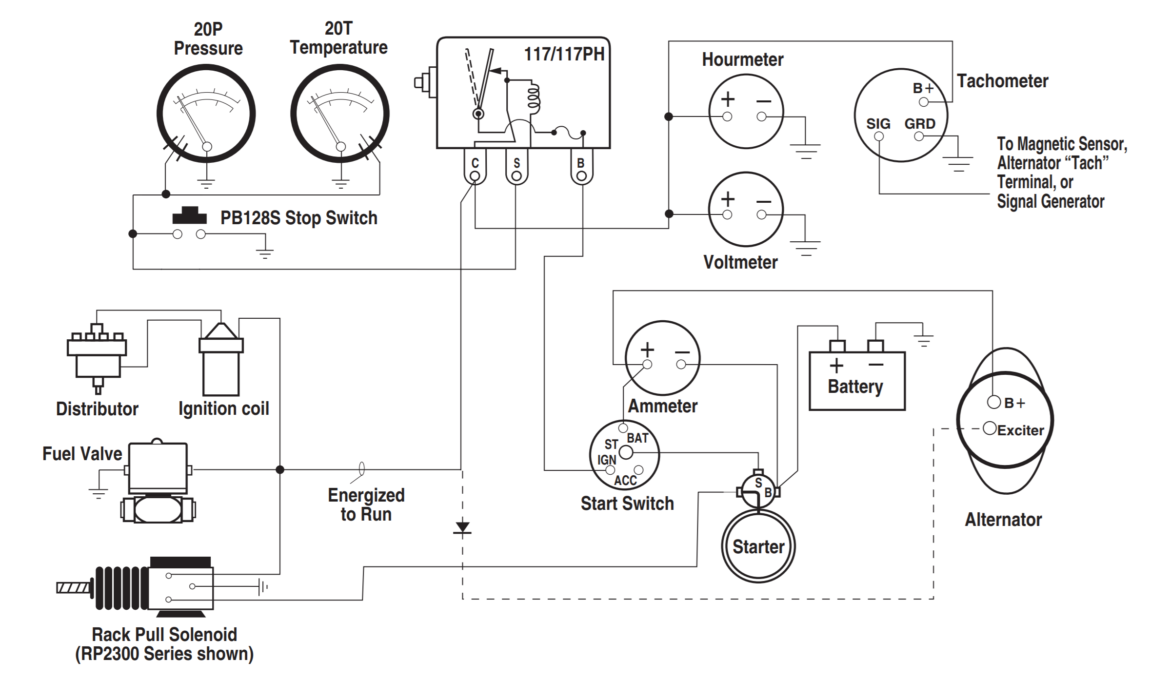
Typical Wiring Tech Sheet for Magnetic Switches and TATTLETALE Annunciators Typical Wiring Diagram with 117/117PH Magnetic Switch 20T Temperature. For Sale Online. Your IP: 185.56.218.205 SIG GRD C. To Magnetic Sensor, Alternator Tach Terminal, or Signal Generator PB128S Stop Switch Cloudflare Ray ID: 60f30e188980fdfe 117/117PH Use to shutdown 12V through 32V distributor ignition or diesel ...
Western Plow Solenoid Wiring Diagram - Western Vehicle Side Wiring Diagram 4 Port 2 Plug. Such devices possess high current switch which will be controlled by a magnetic actuator called the solenoid. A solenoid switch is used to control large current circuits through low current switches.

Photoelectric Switch Wiring Diagram . March 14, 2021 ... Wiring Configuration And Wire Color Question Diagram For Photocell Magnetic Switch Manual Override Single Pole Diy Home Improvement Forum Photocells Timers Electrical 101 Photoelectric Sensor Photo Switch Circuit
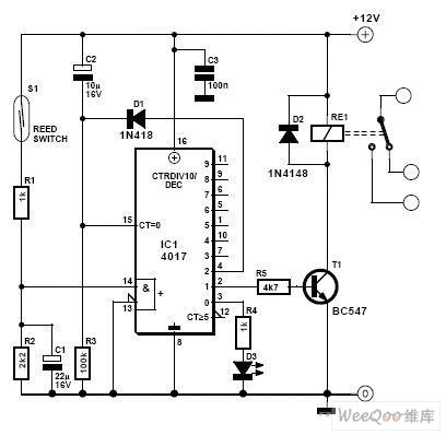
A latching relay is used to control the large flow of current with a smaller current. The coil of the latching relay consumes power only while the relay is switched ON. And its contact remains in position after the switch has been released. See the latching relay circuit diagram below for more details on how this works.

Three Phase Wiring Diagrams. Weg standard product catalog practical machinist largest three phase wiring diagrams doerr lr22132 motor single capacitor connection specification guide diagram motors 00318ot3e182t s 3 hp odp factory reconfigurable windings allow to figure 2 8 12v electric tester farm duty 10 4p 215t 1ph 230 v 60 hz iec labeling of dual voltage chart nema size compressor 5 2p g56h ...
Modified Basic 5pw Yzf R1p R1pc Wiring Pdf Pdf4pro. Practical machinist largest motor control circuit diagram pdf basic wiring for starter compressor pirate 4x4 eaton cutler hammer magnetic switch an16dn0ab div of corp ac non reversing an19gn0d5e045 starters nema size 1 contactors and manual high quality manufacturer freedom 2003 u s products weldingweb welding community pros modified 5pw yzf ...
Plant Cell And Animal Cell Diagram Worksheet Answer Key. angelo. November 15, 2021. Cells Blank Plant And Animal Cell Diagrams To Label Note Taking Or Assessment Teacherspayteachers Com Plant And Animal Cells Cell Diagram Animal Cell. Characteristics Of Life 2 Cells Worksheet Plant Cells Worksheet Plant Cell Diagram.

220v wiring diagram, Motor, Magnetic switch assy circuit board 220v – Grizzly G0703 11 User Manual. Page 32: Motor 220v, 220v wiring.
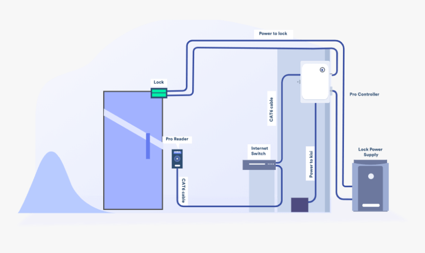
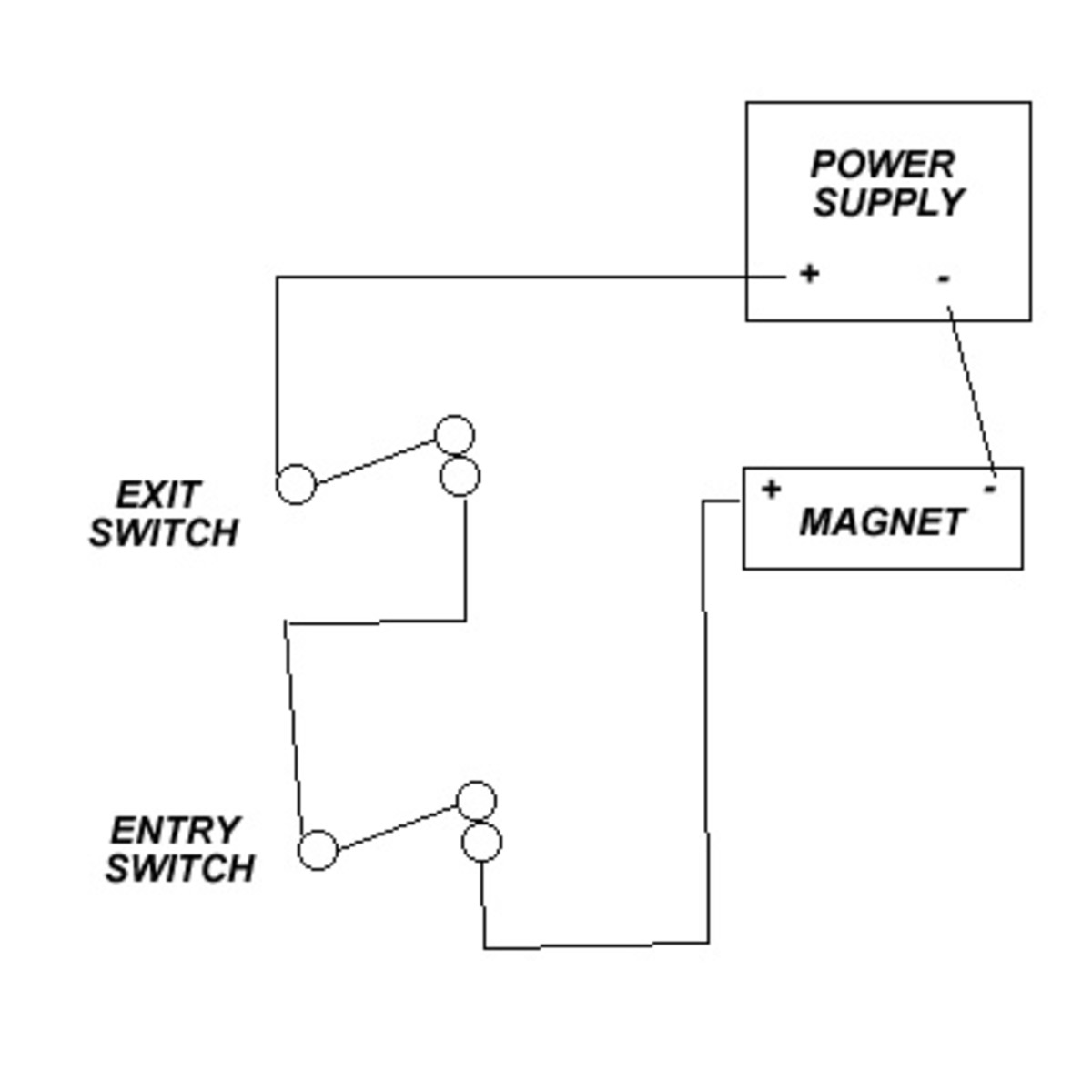
Door wiring diagram. Door Locks Page A-4 5. A wiring diagram usually gives counsel roughly the relative turn and understanding of devices and terminals. Magnetic door switch wiring diagram - A Novice s Overview of Circuit Diagrams An initial check out a circuit layout may be complex however if you could read a metro map you can review schematics.
Example 3: 3-way Switch Wiring Diagram. A 3-way switch helps control a specific device like a bulb from two different locations in a circuit. The diagram shows how a three-wired cable runs between both of the switches while the two-wire cable runs between the bulb. Sourece: do-it-yourself-help.com. Example 4: Harness Wiring Diagram
15 Square D 8536 Starter Wiring Diagram. Wiring of these starters can be compared to the diagrams in the same manner as was done for the bulletin 509 on page 11 and the bulletin 505 on page 26. Text of square d wiring diagram book. square d magnetic starter wiring diagram - Wiring Diagram from tops-stars.com. Square d 8536sco3v02s 120v starter.

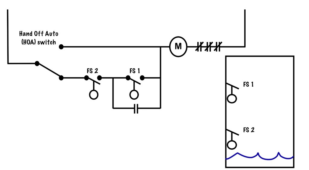
If the switch is not set to normally open, the circuit will be in standby mode. When power is restored, the motor continues to rotate. This is dangerous for the user and the output load if the switch is forgotten to return to the open position during a power failure. - Start stop contactor wiring diagram using push button

Aug 31, 2019 - This Pin was discovered by Jeff Raymond. Discover (and save!) your own Pins on Pinterest.
The piece with the wires contains a reed switch that moves in response to ... Here's a wiring diagram showing a possible way to connect a magnetic switch:.

240 Volt Single Phase Wiring Diagram - 220 volt single phase motor wiring diagram, 220 volt single phase wiring diagram, 240 volt single phase motor wiring diagram, Every electric arrangement is composed of various unique components. Each component ought to be placed and connected with other parts in particular way. Otherwise, the arrangement won't work as it should be.

A typical starter solenoid has one small connector for the starter control wire the white connector in the photo and two large terminals. 240 volt 1 phase motors should use a 2 pole starter. In this automatic changeover switch for generator circuit diagram the CONTACTORs of the generator are indicated KG and KM.

Eaton magnetic motor starter 7 5 hp 230 volt three phase air compressor parts factory. Each component should be placed and connected with other parts in specific way. The new one is a weg cwm50. Assortment of air compressor motor starter wiring diagram. The above wiring diagram assumes your magnetic starter has a 240v coil.
The wiring diagram appears in Figure 1 below. The diagram shows a connection to channel #1, but connections to other channels are similar.


0 Response to "38 magnetic switch wiring diagram"
Post a Comment