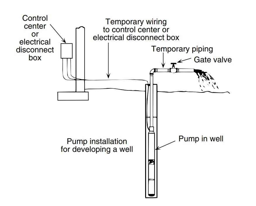
36 deep well pump installation diagram
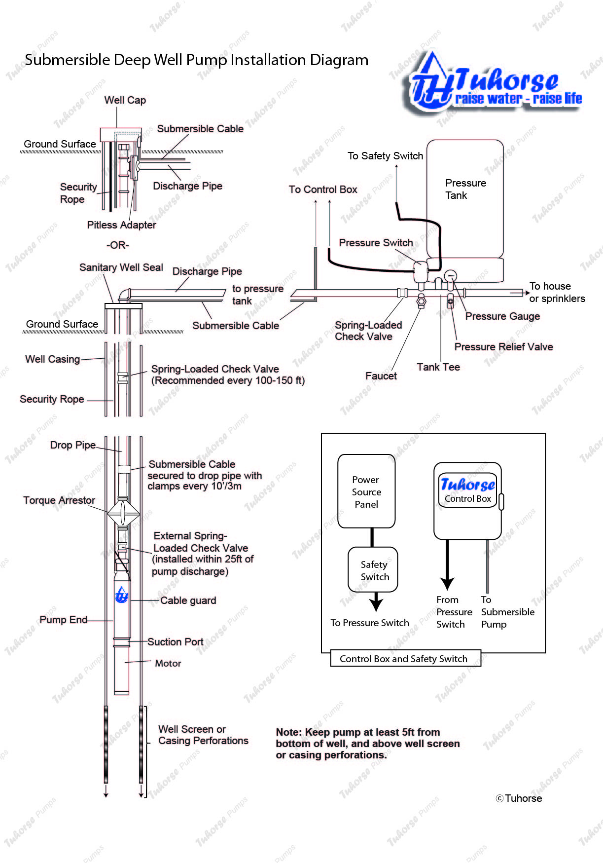
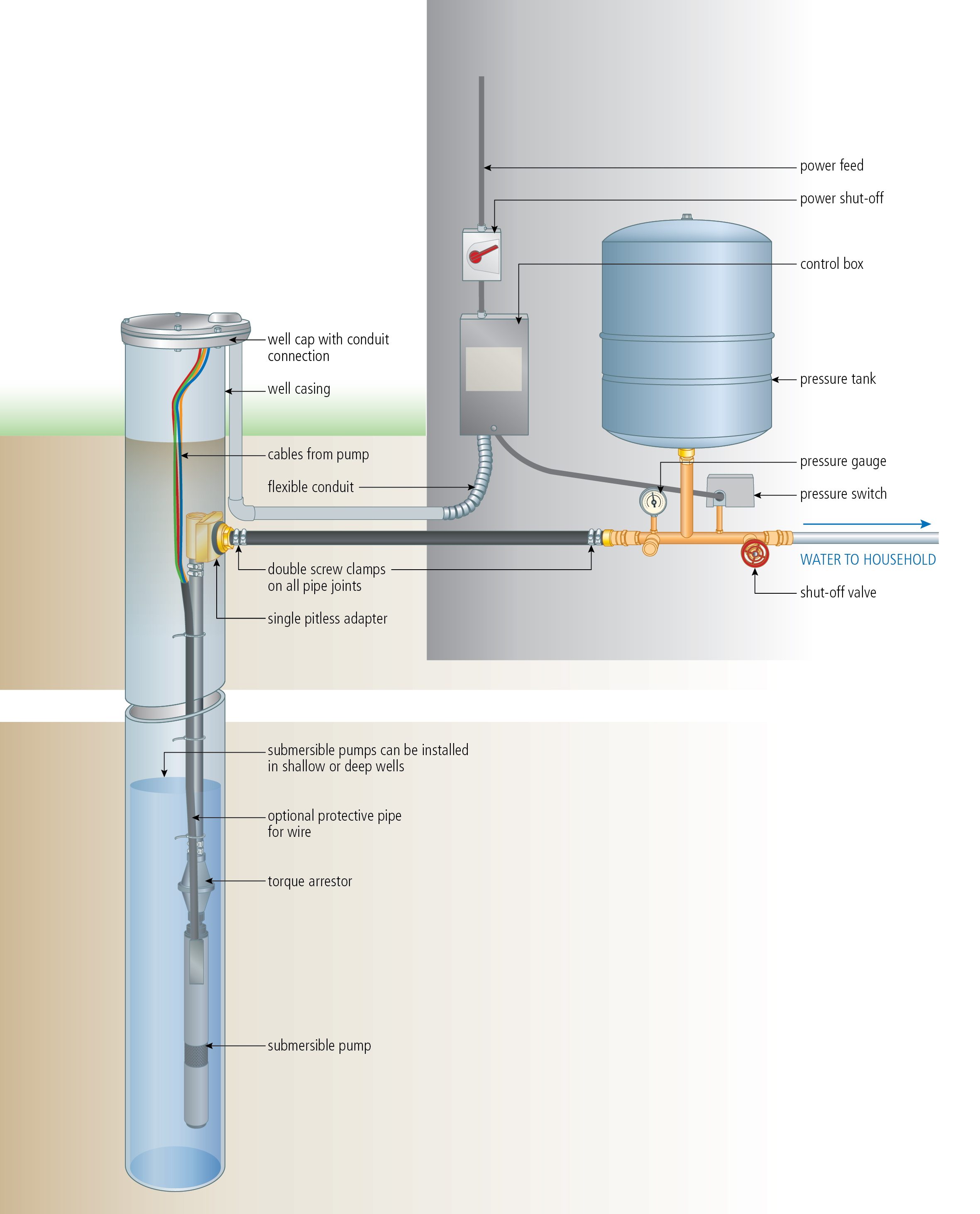
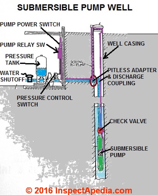
Submersible Deep Well Pump Installation - Domestic water system. For a printer friendly version, click here. Diagram of deep well submersible well pump installation with sanitary well seal and pitless adapter. Below is a video demonstration of assembling the pump and motor: YouTube. Tuhorse North America.
Medium size of wiring diagrams 3 wire well pump wiring diagram deep well pump installation deep well pumping operations article about deep well pumping operations by the free dictionary a sump level control.
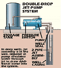
well for service. 6. Well Seal Provides a positive seal inside casing in above-ground installations. 7. Check Valve Installed near the tank inlet to hold water in the tank during pump installation when the pump is idle. 8. Tank Tee Connets water line from pump to pressure tank and service line from tank to house. Taps are provided to accept ...
Deep well pump installation diagram
Well Diagram. The quality water system products described here and illustrated on the front page are some of the Baker Water Systems products used in a typical well system. (The section in the catalog where these items can be found is located in parentheses) This list and the illustration on the front page are not intended as an installation guide.
Diagrams --Typical Pump Installations. The information provided here is for educational purposes only. Technically qualified personnel should install pumps and motors. We recommend that a licensed contractor install all new systems and replace existing pumps and motors. Failure to install in compliance with local and national codes and ...
STEP #4 - Remove the existing well cover or well seal, whichever you may have and set it aside. *If you have a submersible pump, be sure to shut the electricity off to the pump before beginning the installation of the Bison Hand Pump* If you are installing in the same casing as an electric submersible pump, in most cases the
Deep well pump installation diagram.
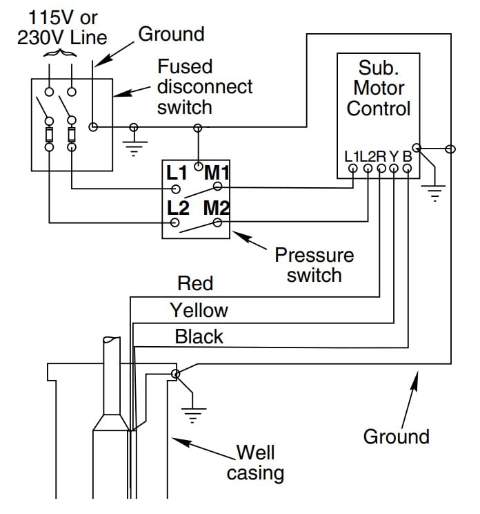
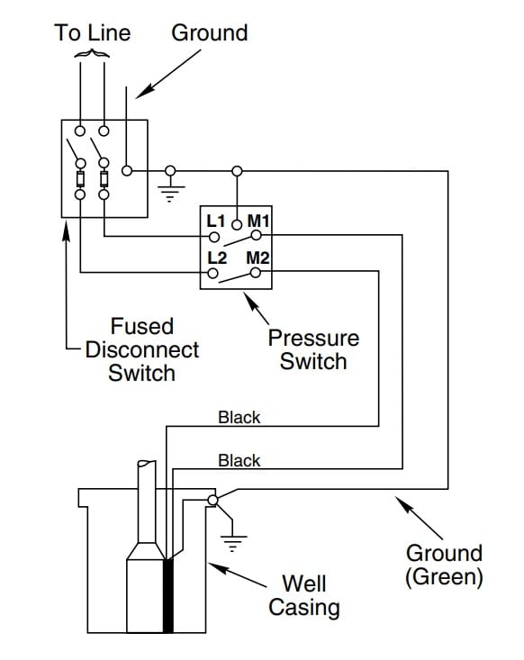
Deep submersible well pumps will be either 2-wire or 3-wire well pumps, and 3-wire well pumps will need a separately installed control box. Two-Wire Well Pump Wiring Diagrams. 2-wire well pump diagrams are slightly easier to understand, and are more straight-forward to wire. Black wires go to black wires, and the green wire (the ground) goes to ...
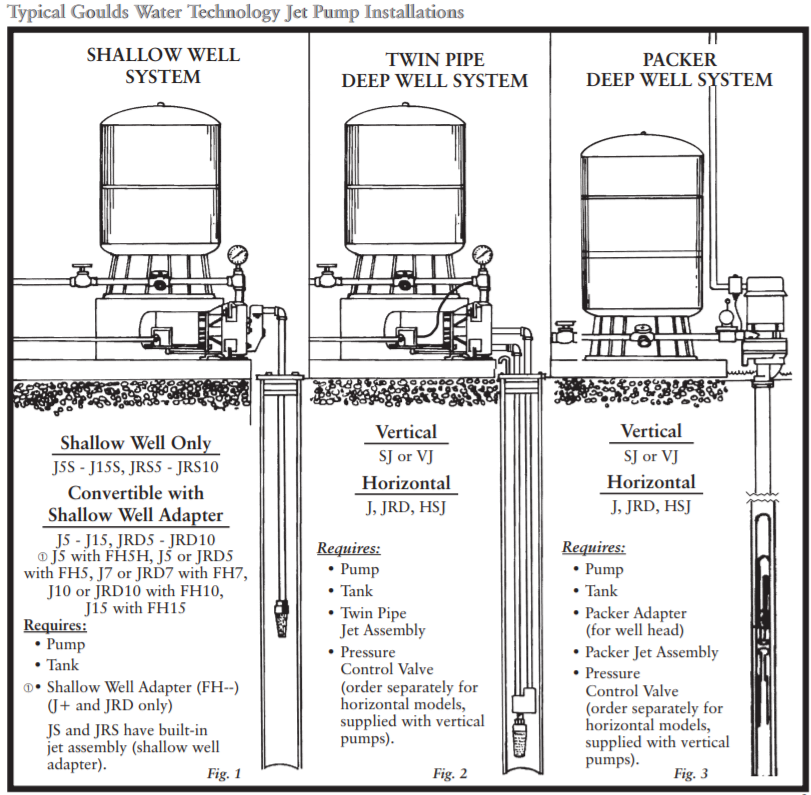
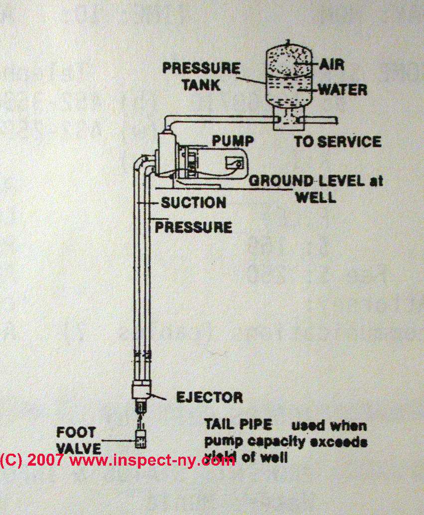
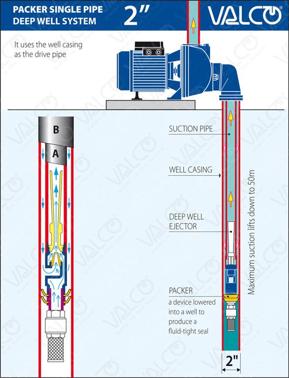
the pump and well will aid in servicing. Be sure to leave enough room so that wrenches can be used easily. Deep Well (Double Pipe System) Where water level is greater than 25 feet and inside diameter of well is four (4) inches or larger (Fig. 1). 1. Attach the foot valve to the ejector using a galvanized steel or plastic nipple.
Home > Technical Information > Pumps Technical Data > Submersible Well Pump Technical Data > Submersible Well Pump Accessories Installation Diagram This illustration is for educational purposes It is not intended as an installation guide.
Pressure Tank Installation Diagram Luxury Reco Usa Mercial Hot Water Storage Tanks. READ Tire Sizes Diagram. deep well plate, deep well platten 24 square, deep well platten, deep well pump, deep well drilling cebu, deep well 96 well plate, deep well ethiopia, deep nwell diodes at the source of an nmos, deep well pumps germany, deep well 96 well ...
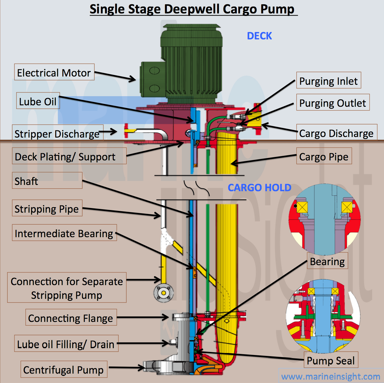
Deep Well Pump Installation Diagram. diagrams typical pump installations submersible well pump accessories installation diagram ask a question about diagrams typical pump installations deep well pumps submersible well pump accessories installation diagram submersible well pump accessories installation diagram this illustration is for educational purposes it is not intended as an installation guide
Well Pumps & Well Design 2 Water quantity requirements including the design population, usage per capita, capacity factor and pumping day will be specified in the 1010 and 1015 documents. Nevertheless, it is understood that despite the best efforts of the contractor, adequate water may not be
deep well pump installationdeep well pump installation diagramdeep well pump installation instructionsdeep well pumpdeep well drillingdeep well water pumpdee...
Submersible Well Pump Wiring Diagrams Lovetoknow. Well pump installation guide water wiring troubleshooting everbilt 1 hp submersible 3 wire motor 4 2 10 install a 6 lessons three diagrams rs485 hydrostatic cesspool deep sea 110volt electrical 120v shurflo 9300 9325 083 wires cut directly to generator pumps vs using relays 230v systems lindsay drilling 110 v terry love franklin electric pro ...
Deep Well Pump Installation Part superstore. Huge selection of Deep Well Submersible Pump Installation Parts. Buy Submersible Well Pump Installation Part Direct and save.
To prevent overpumping the well, a deep-well jet-pump installation may include a 35-ft.-long tailpipe. It's connected to the intake end of the jet housing and extends down into the well.
Deep Well Pump Installation Diagram. November 26, 2018November 25, 2018. Sponsored links. Ford Starter Solenoid Problems. 60 Amp Disconnect Switch. Evinrude Ignition Switch Wiring Diagram. Chrysler Radio Wiring Diagrams.
Deep Well Pump Installation Diagram. Deep Well Pump Installation Diagram. G. Gaberial. 81 followers. Well Water System. Water Well. Water Systems. Shallow Well Jet Pump. Deep Well Pump. Deep Well Submersible Pump. Firefighter Photography. Relief Valve. Drain Plugs. More information.... More like this ...
If you're replacing your deep well pump, our expert from Everbilt will guide you. This tutorial for an Everbilt jet well pump installation shows you step by ...
On a 45 foot deep well using a submersible pump, the pump is at the well bottom. You may need no check valve at all. Your system may use a Dole valve if your well does not have a terriffic flow rate, since with a 45 foot deep well, even if the water is near the well top, you don't have more than about 90 gallons of static head in the well.
JET PUMP INSTALLATION MANUAL SHALLOW WELL JET PUMPS STEP 1 Make sure the well is pumped clean and that sand and grit are absent. STEP 2 Before installing a shallow well or centrifu-gal pump make sure the total suction lift does not exceed 25 feet. STEP 3 For convertible jet pumps attach the ejector to the pump housing, making sure that the 1 1/4"
Well pumps are used to bring water from an underground water table into a well where it is more easily accessible. An electromechanical system then moves the water from the well to an individual home or other structure. When it comes to installing a well pump, you have a choice between shallow well pumps and deep well pumps.. Choose the right type for your particular well.
Oct 16, 2019 - Submersible well pumps are sturdily built to survive about 25 years in a lonely place often hundreds of feet down a well casing underground and under water.
A nice example table of Deep Well 2-Line Jet Pump Capacities for 1/2 hp and 1 hp deep well pumps is provided in the Water Ace Jet Pump Installation Manual and excerpted below to illustrate the factors that determine well pump capacity.
Install a Submersible Pump Lesson#2: Protect Those Wires. The wear on this cable was caused by the submersible pump swaying inside the well casing after the torque of start up. Pulling a failed submersible pump teaches lessons, and one of the most surprising is the reason why many pumps fail.
deep well pump installation diagram with water wiring price ph. Architectural wiring diagrams play the approximate locations and interconnections of receptacles, lighting, and steadfast electrical facilities in a building. Interconnecting wire routes may be shown approximately, where particular receptacles or fixtures must be upon a common ...
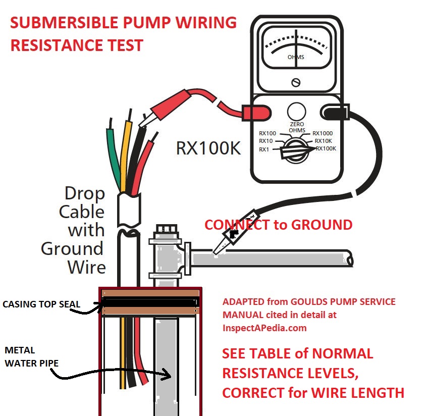
Typical pumps used in a submersible pump installation are either a two or three wire pump. The two wire pumps have the starting capacitor built into the submersible motor whereas the three wire pumps do not have the capacitor built into the motor, they require a control box which is normally found in the pump house at the well head. For more on ...
extremely deep wells. Threaded schedule 80 PVC and a heavy grade poly pipe are also available and are much lighter and easier to work with. 12. Position a torque arrestor directly above the top of the pump. This will center the pump in the well and keep the pipe from twisting due to torque created by the pump motor. 13. IMPORTANT!
TYPICAL DEEP WELL JET PUMP INSTALLATION a captive air Jet pumps usually come with a 30-50 pressure switch factory installed on the pump. If replacing the switch we recommend using one with a 30-5 psi setting. 1. Deep well jet systems are used when the water depth is between 20' and 80'. For wells deeper than 80' a submersible pump system ...

Hot submersible deep well pump water pump 0.5hp 40m 220v stainless steel submersible pump irrigation garden home agricultural to
Goulds sj20, vertical deep well jet pump, sj series, 2 hp, 230 volts, 1 phase, 3 stages, 1-1/4" npt suction, 1" npt discharge, cast ion body









0 Response to "36 deep well pump installation diagram"
Post a Comment