42 transfer function from block diagram
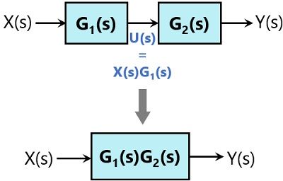
2. Block diagram models The block diagram is a diagrammatic means to represent the cause-and-effect relationship of system variables. It consists of unidirectional, operational blocks that represent the transfer function of the variables of interests. Fig.4: Components of a block diagram for a linear, time-invariant system
5 Nov 2018 — The output is related to the input through a function called transfer function. This function is represented by a block and the complete diagram ...5 pages
Transfer function from block diagram
Chapter 2 Transfer Functions and Block Diagrams 4 2. Transfer Functions and Block Diagrams 2.1 Introduction - Review of Laplace transform - Using Laplace transform to solve a differential equation 2.2 Review of Laplace Transforms Definition: The Laplace transform off (t) , a sectionally continuous function of time, denoted by L[ f (t)], is ... Transfer function into block diagram and matrix form. 0. Closed Loop transfer Function. 0. Transfer Function. Hot Network Questions What would be the easiest way for a personality-altering bioweapon to be transmitted? He said that because there is a component in the feedback loop (so it's not unity gain) I had to use this formula to convert the transfer function into the 'equivalent unity gain transfer function': Ge(s) = G(s) / (1 + H(s)G(s) - G(s)) where G(s) is the top part of the block diagram and H(s) is the feedback loop.
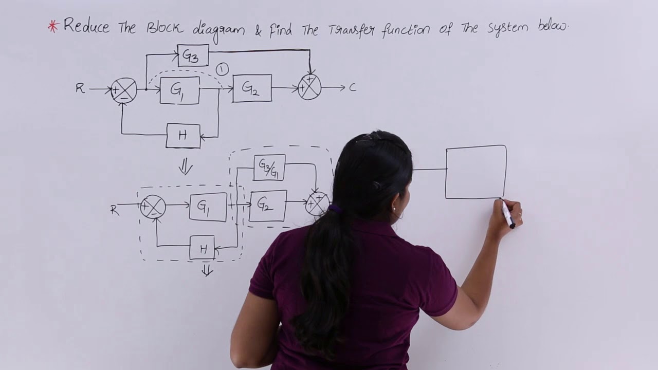
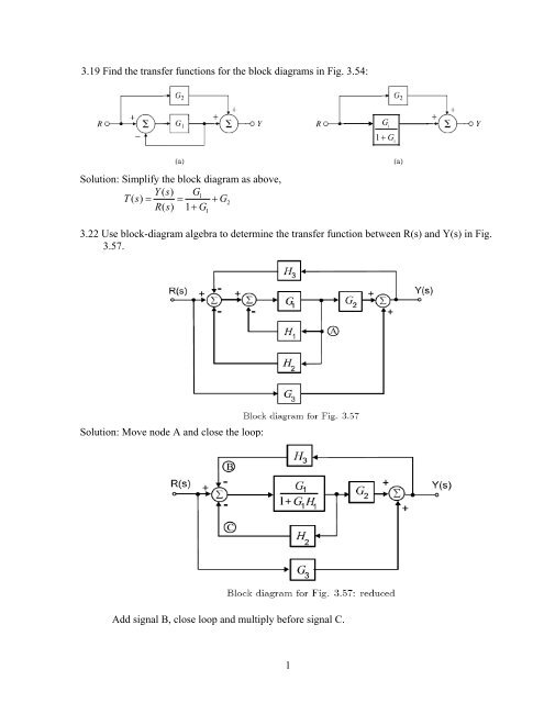
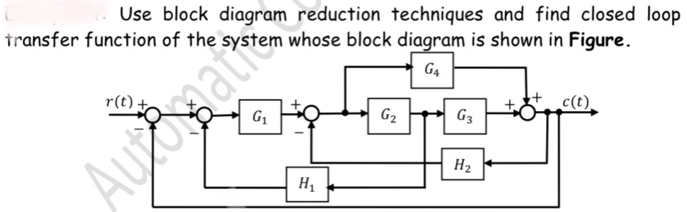
Transfer function from block diagram. 3.22 Use block-diagram algebra to determine the transfer function between R(s) and Y(s) in Fig. 3.57. Solution: Move node A and close the loop:.7 pages Transfer function block diagram. 1. Find the difference equation and draw the simulation diagram. 4. Find transfer function from root locus and step response diagram? 3. Poles and zeros of a transfer function. 0. Block diagram for a complex impulse response. 0. Inverse Fourier of Two-Pole Transfer Function. Example · Step 1 − Find the transfer function of block diagram by considering one input at a time and make the remaining inputs as zero. · Step 2 − Repeat step ... BLOCK DIAGRAM ALGEBRA AND TRANSFER FUNCTIONS OF SYSTEMS [CHAP. 7 We do not apply Step 3 at this time, but go directly to Step 4, moving takeoffpoint I b'eyond block G2 + G3: i [ .1 .2 C G2 + G3 We may now rearrange summing points 1 and 2 and combine the cascade blocks in the forward loop using ...
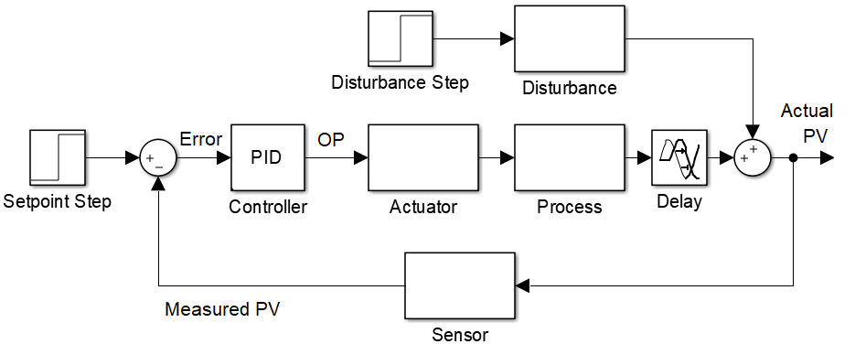
160 BLOCK DIAGRAM ALGEBRA AND TRANSFER FUNCTIONS OF SYSTEMS [CHAP. 7 Let the - 1 block be absorbed into the summing point: Step 4c Step 5: By Equation (7.3), the output C, due to input U is C, = [G2/(1 + G1G2)]U. The total output is C=C,+C,= [ ~ 1 +G2G2] [ A] [ A] IGIR + 7.8 REDUCTION OF COMPLICATED BLOCK DIAGRAMS The block diagram of a practical feedback control system is often quite complicated. G(s) – Forward path transfer function. H(s) – Feed back path transfer function . Block diagram reduction technique . Because of their simplicity and versatility, block diagrams are often used by control engineers to describe all types of systems. A block diagram can be used simply to represent the composition and interconnection of a system. Transfer Functions. A transfer function is a mathematical formulation that relates the output variable of a device to the input variable. For linear devices, the transfer function is independent of the input quantity and solely dependent on the parameters of the device together with any operations of time, such as differentiation and integration that it may possess. Block Diagram of Closed Loop Control System. In a closed-loop control system, a fraction of output is fed-back and added to the system’s input. If H (s) is the transfer function of the feedback path, then the transfer function of the feedback signal will be B (s) = C (s)H (s). At the summing point, the input signal R (s) will be added to B (s ...
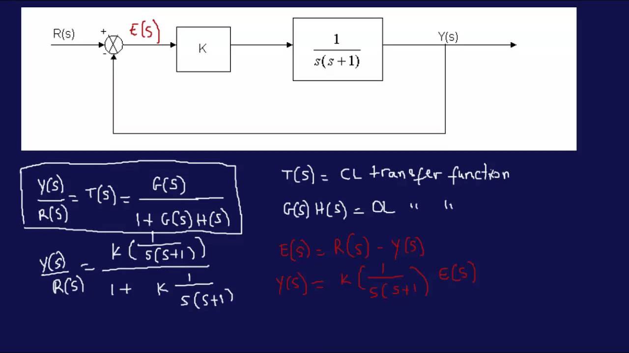
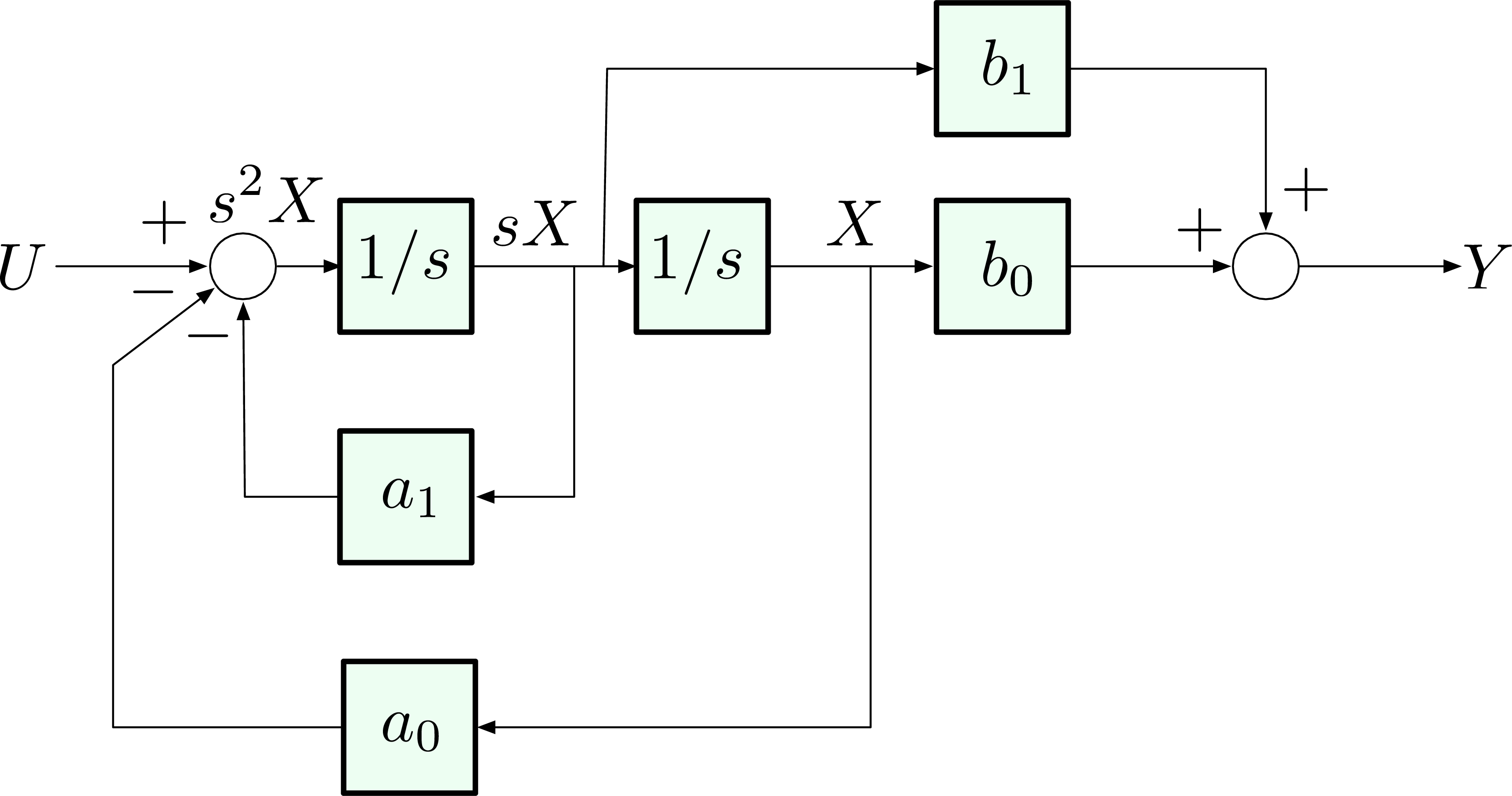
9 May 2021 — For example, a simple mass driven by a controlled force has transfer function P(s)=1/ms2, which relates the input, force u(s), into the output, ... He said that because there is a component in the feedback loop (so it's not unity gain) I had to use this formula to convert the transfer function into the 'equivalent unity gain transfer function': Ge(s) = G(s) / (1 + H(s)G(s) - G(s)) where G(s) is the top part of the block diagram and H(s) is the feedback loop. Transfer function into block diagram and matrix form. 0. Closed Loop transfer Function. 0. Transfer Function. Hot Network Questions What would be the easiest way for a personality-altering bioweapon to be transmitted? Chapter 2 Transfer Functions and Block Diagrams 4 2. Transfer Functions and Block Diagrams 2.1 Introduction - Review of Laplace transform - Using Laplace transform to solve a differential equation 2.2 Review of Laplace Transforms Definition: The Laplace transform off (t) , a sectionally continuous function of time, denoted by L[ f (t)], is ...
Problem 1 On Block Diagram Reduction Youtube
Transfer Functions In Block Diagrams Dynamics And Control

Control Theory What Is Block Diagram For These Transfer Functions All About Circuits
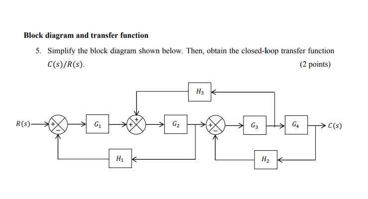
Solved Block Diagram And Transfer Function 5 Simplify The Chegg Com

Block Diagram Reduction Rules For Finding Transfer Function Youtube
Block Diagram Reduction Rules With Example Electronics Coach
1 3 19 Find The Transfer Functions For The Block Diagrams In Fig 3 54

Solved Write Matlab Program To Find Transfer Function Y X Chegg Com

Transfer Function Block Diagram Of The Avr System Download Scientific Diagram
Get Transfer Function From Block Diagram Physics Forums
H1 Align Center Enotes Mechatronics And Controls H1
Control Systems Block Diagram Reduction

Solved Exercise 2 Find The Transfer Function For The Block Chegg Com
.png?revision=1)
11 5 Block Diagrams And Transfer Functions Of Feedback Systems Engineering Libretexts
1

Block Diagram Reduction To Find Closed Loop Transfer Function For Control System Model In Hindi Youtube
Solved 1 Simplify The Block Diagram Shown In Figure And Obtain The 1 Answer Transtutors

Block Diagram Of A Transfer Functions Model Of The Control System Download Scientific Diagram

Transfer Function Block Diagram Of The Pid Controller Based Avr Design Download Scientific Diagram
Transfer Function Block Diagram Signal Processing Stack Exchange

Answered Find The Transfer Function Of The Bartleby

Reduce The Block Diagram Shown In Figure 5 9 To A Single Transfer Function Holooly Com

System Dynamics Dr Mohammad Kilani Ppt Download
1
Finding Transfer Fucntion Of A Block Diagram Example Block Diagram Reduction Method Youtube

Transfer Function Dan Diagram Blok Jembatan Antar Disiplin Ilmu Automationid
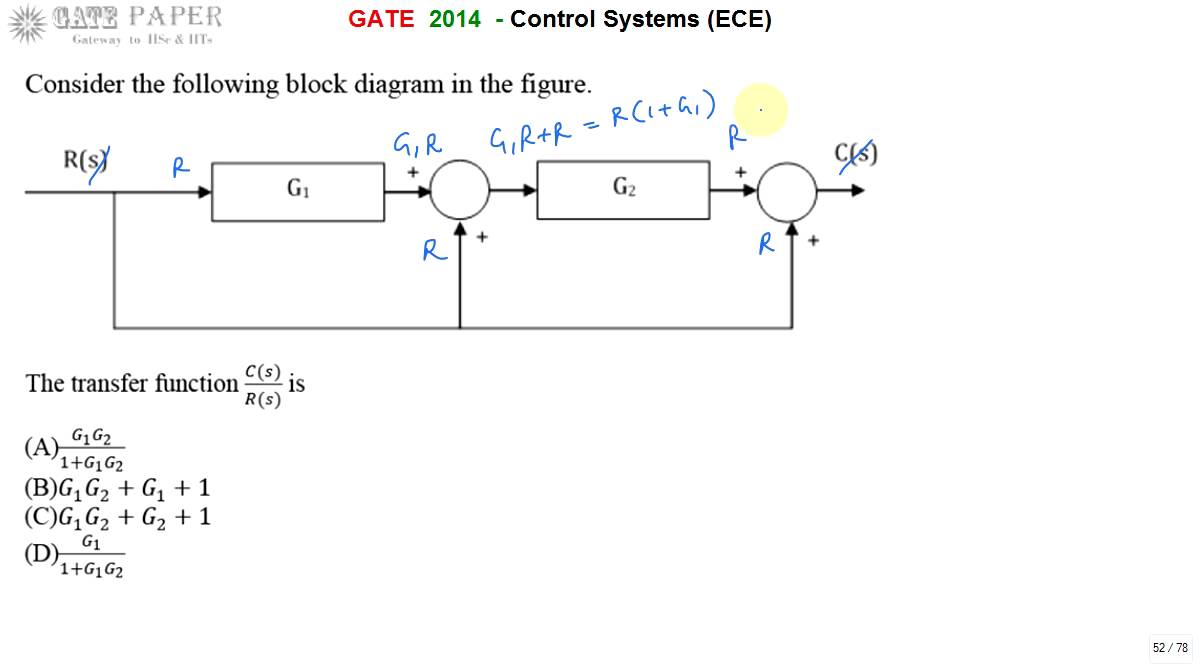
Gate 2014 Ece Transfer Function Of Given Block Diagram Youtube
Control Systems Block Diagram Reduction

Solved Using Block Diagram Algebra Determine The Open Loop Chegg Com
1
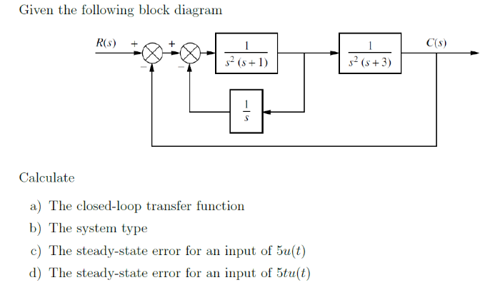
Solved Given The Following Block Diagram R S A 52 5 1 Chegg Com
Answered Find The Transfer Function Of The Bartleby

Modeling Simulation Of Dynamic Systems Lecture7 Block Diagram
Deriving Transfer Function From Block Diagram 1 Fe Eit Exam Review Youtube

Small Perturbation Transfer Function Block Diagram Of The Download Scientific Diagram
Converting A Transfer Function To State Space Representation Dademuchconnection

Engineer On A Disk

Transfer Function Block Diagram Computer Electronics Journal
Ece 486 Control Systems
1 3 19 Find The Transfer Functions For The Block Diagrams In Fig 3 54

File Block Diagram For Sensitivity Transfer Function Svg Wikipedia
Answered Use Block Diagram Reduction Techniques Bartleby
0 Response to "42 transfer function from block diagram"
Post a Comment