41 wet switch wiring diagram
We will now go over the wiring diagram of a DPDT Toggle Switch. Below is the schematic diagram of the wiring for connecting a DPDT toggle switch: DPDT Toggle Switch. A DPDT toggle switch has 6 terminals. Terminals 3 and 4 represent the toggle switch. These terminals receive the power necessary to drive the loads on terminals 1 and 5 and 2 and 6. Multiple Light Wiring Diagram. This diagram illustrates wiring for one switch to control 2 or more lights. The source is at SW1 and 2-wire cable runs from there to the fixtures. The hot and neutral terminals on each fixture are spliced with a pigtail to the circuit wires which then continue on to the next light.
Place the wet switch with the padded side down on the surface to be monitored. Route the cable from the wet switch to cooling control voltage transformer as shown in the wiring diagram. Wire can be extended if necessary. Cut common wire of transformer. Connect black wire from wet switch to same wire on transformer where common was cut.

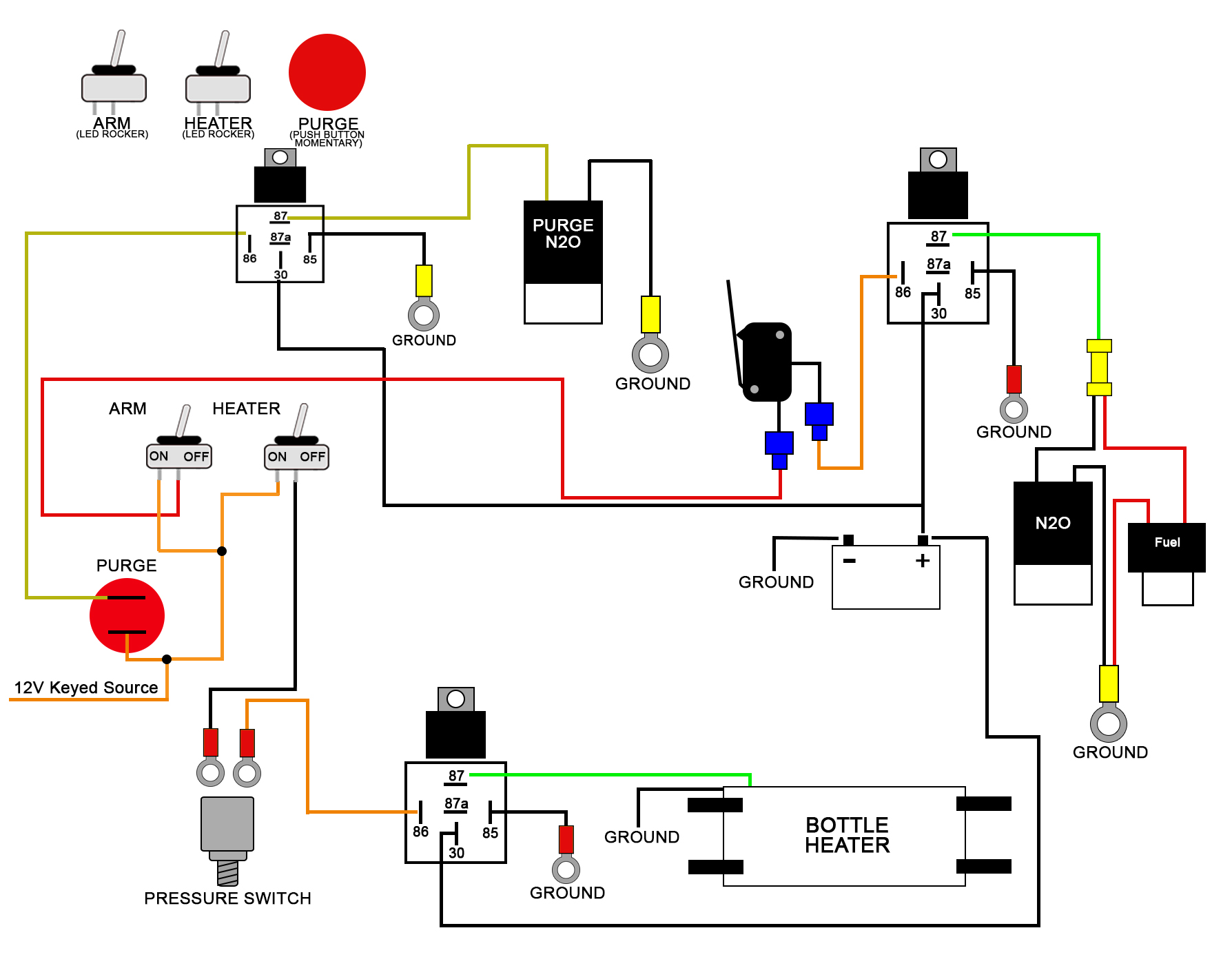
Wet switch wiring diagram
MAZDA WIRING DIAGRAMS WORKSHEET #1 1. Describe the meaning of the dotted line in the diagram component P. 2. Describe and identify the diagram component Q. 3. Describe and identify the "R/B" in diagram component R. 4. Describe and identify the "F" in diagram component S. 5. Describe and identify the diagram component T. 6. DiversiTech WS-1 - Wet Switch Flood Detector - The wet switch flood detector is a solid state control designed to help prevent flooding, damage to carpets, walls, furniture, ceilings, etc. It now has a built-in test and reset button for easier installation. It turns the system off when moisture due to condensate or drain leaks is detected. One or two drops will cause Wet Switch to turn off a ... UNDERSTANDING TOYOTA WIRING DIAGRAMS WORKSHEET #1 1. Describe the meaning of the "C13" in the diagram component Q. 2. Describe the meaning of the "G-W" in diagram component R. 3. Describe the meaning of the "2" in diagram component S. 4. Describe the meaning of the "S/D" in diagram component T. 5. Describe and identify the diagram component U. 6.
Wet switch wiring diagram. A. Connect “RED”, “Input 24 VAC (Hot)” and “Gray” “Common” wire of AG-4200E to 24 ... mended that a damp cloth be placed under the lines being brazed.5 pages Connection showing two or more Wet Switches in series ... transformer as shown in the wiring diagram. Wire can be extended. DiversiTech WS-1 Wet Switch Flood Detector Double Throw Relay-Allows for wiring to interrupt system and to sound an alarm (by others) when moisture is detected; The Wet Switch is designed to interrupt the operation of cooling systems. However, it is a water activated switch and can be used in a variety of other applications /5 (42). Refer to wiring diagram, Figure 7, for wiring procedure on all other heaters. The Remote Fan Switch is mounted external and remote from the unit heater. Hopefully your heater came with wiring instructions for the stat as it will show both single pole and two pole stat wiring diagrams.
SAFE-T-SWITCH® SS610E WIRING DIAGRAM www.rectorseal.com. R50496-0819. 1. (Internal Installation) Place CPU inside evaporator enclosure or line set cover. Place Wet Switch, padded side down, on the surface to be monitored. 3. Connect wiring as shown in the diagrams on page 2. Wires may be extended as necessary, but avoid excess run lengths. 4. Restore power to the system. Controlling Selected Components System components such as compressors, electric valves, condenser Model No. WS-1 WET SWITCH ... FLOOD DETECTOR. Wet Switch WS-1 security sensors pdf manual download. ... Connect wiring as shown in the diagrams on page 2. Wires may be. The wiring diagrams are very .Route the cable from the wet switch to cooling control voltage transformer as shown in the wiring diagram. Wire can be extended if necessary. Cut common wire of transformer. Connect black wire from wet switch to same wire on transformer where common was cut. Connect green wire from wet switch to common wire that ...
UNDERSTANDING TOYOTA WIRING DIAGRAMS WORKSHEET #1 1. Describe the meaning of the "C13" in the diagram component Q. 2. Describe the meaning of the "G-W" in diagram component R. 3. Describe the meaning of the "2" in diagram component S. 4. Describe the meaning of the "S/D" in diagram component T. 5. Describe and identify the diagram component U. 6. DiversiTech WS-1 - Wet Switch Flood Detector - The wet switch flood detector is a solid state control designed to help prevent flooding, damage to carpets, walls, furniture, ceilings, etc. It now has a built-in test and reset button for easier installation. It turns the system off when moisture due to condensate or drain leaks is detected. One or two drops will cause Wet Switch to turn off a ... MAZDA WIRING DIAGRAMS WORKSHEET #1 1. Describe the meaning of the dotted line in the diagram component P. 2. Describe and identify the diagram component Q. 3. Describe and identify the "R/B" in diagram component R. 4. Describe and identify the "F" in diagram component S. 5. Describe and identify the diagram component T. 6.


0 Response to "41 wet switch wiring diagram"
Post a Comment