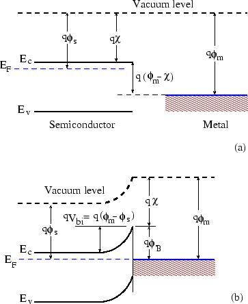
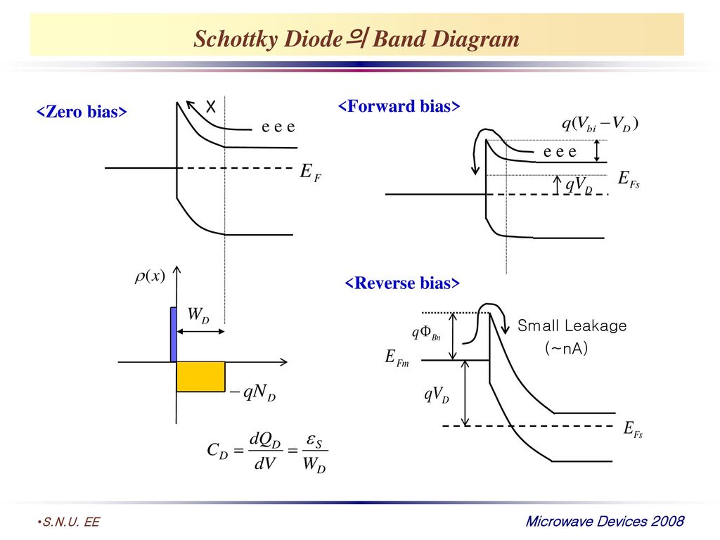
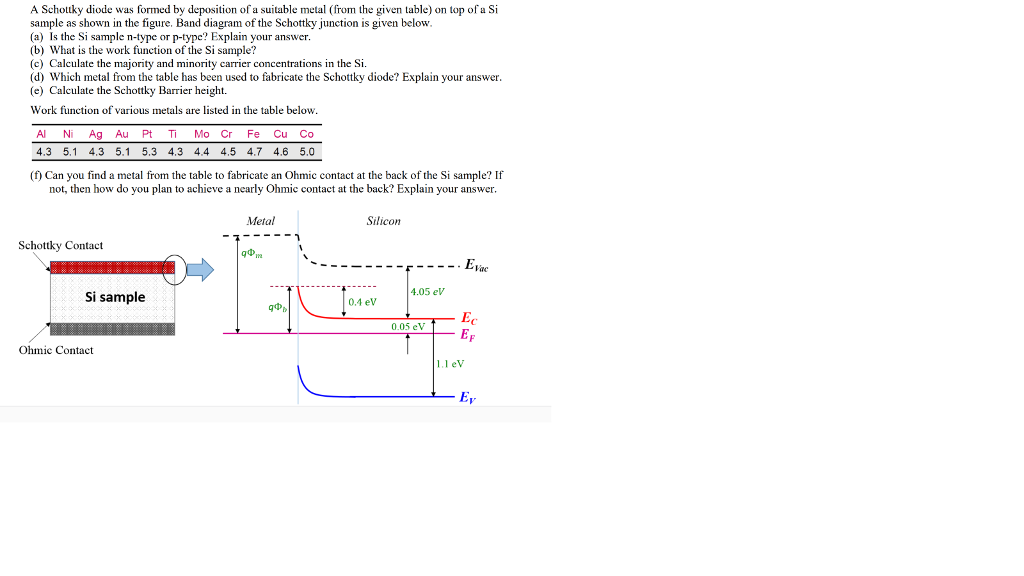
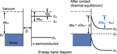
41 schottky diode band diagram
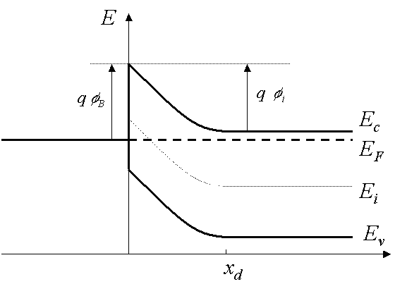
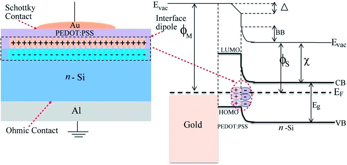
d) Energy band diagram of the Si-Cu Schottky interface and SPP detection mechanism via IPE. e) 3D AFM image and f) false-color SEM image of the electronic-plasmonic transducer. Figure 1c shows the mechanism of SPP excitation from biased tunnel junctions, where (some) electrons transverse the tunnel barrier inelastically and couple with the ... Energy Band diagram for a P-type Schottky Contact. ... The packaged Schottky diode is expected to have near ideal behavior. It is a commercially available, discrete device that is silicon based and has an internal series resistance of 47 Ohms. The Schottky parameters derived from Eqs.
This RF preamplifier is designed for 6-meter frequency band. Meaning it is suitable for 60 to 70 MHz frequency which are generally used for TV signal transmissions. Tuning is not required, since the circuit has a broadband 10 MHz range. RF Meter Circuit. Mixer-type Schottky diodes will be able to detect rf signals from approximately -35dBm and ...

Schottky diode band diagram
Different types of diodes have different voltage requirements. For Silicon Diodes, the forward voltage is 0.7V and for Germanium diodes, it is 0.3V. Usually, in Silicon Diodes, the dark band on one end of the diode indicates the Cathode terminal and the other terminal is anode. The formation of the p-n heterojunction diode with bipolar action was evidenced by comparing it with the Schottky junction. The energy band diagram of the p-n heterojunctions was predicted based on Anderson's rule. The staggered (type-II) band alignment with ΔE c = 3.5 eV and ΔE v = 2.9 eV was determined. Advantages of Semiconductor. 1.Because of their dependability, compactness, and low cost, semiconductor devices are widely used in many applications. 2.A semiconductor is a distinct component that is utilised in optical sensors, power devices, light emitters, and solid-state lasers. 3.Electronic circuits made of semiconductor devices are simple ...
Schottky diode band diagram. a, b Schematic diagrams of atomic structure (left) and band structure (right) of general (a) and optimized (b) Schottky junctions.The purple sphere is the element of the conventional metal ... Product Overview. The Schottky Power Rectifier employs the Schottky Barrier principle with a barrier metal that produces optimal forward voltage drop−reverse current trade off. Ideally suited for low voltage, high frequency rectification, or as a free wheeling and polarity protection diodes in surface mount applications where compact size and weight are critical to the system. (a) Schematic of the Schottky barrier diode (SBD) for its measurement. (b) Schematic of the SBD for its simulation. Dynamic measurement test sequence with an STS8200. DPP-DTT has band gap of 1.7 eV and electron affinity of 3.5 eV [].Energy diagram of Au/DPP-DTT/Al structure in equilibrium is shown in Fig. 1, where the polymer layer is sandwiched between our choice of metal contact.As shown, the structure allows for a Au/DPPDTT ohmic contact and Al/DPP-DTT Schottky barrier junction for intended diode like
diode. The schematics and simulated energy band diagram of the dielectric heterojunction diode areshown in Figs. 1(a)-1(c). Itconsists of a 20nmhigh-k BaTiO 3 layer(e r 260) on a b-Ga 2O 3 lightly doped n-type drift layer. A Schottky metal contact is formed on the BaTiO 3 layer. BaTiO 3 is a perovskite material with a bandgap of 3.4eV. It has impedance matching of Schottky diodes at Port1, Port2 and Port3, the Fig. 1 Schematic diagram of the conventional mixer with two short-ended stubs Fig. 2 Layout of conventional V-band mixer with two short-ended stubs Fig. 3 Simulation results of (a) S(J1,LO) and S(J1,RF) of conventional mixer, (b) S(IF,J1) of conventional mixer GaN diodes exhibit higher breakdown voltage characteristics than Schottky diodes made of silicon, and thus they are suitable for high input power devices. The design difficulty of GaN diodes in the C-Band (4∼8 GHz) or higher band is very difficult, and the manufacturing cost is high. We have investigated Schottky barrier diode based on MoTe $$_2$$ 2 with Au and Cr/Au asymmetric contacts. While many metals show strong Fermi level pinning close to the valence band of MoTe $$_2$$ 2 , one can change MoTe $$_2$$ 2 -Au Schottky contact via simple thermal annealing. The Schottky diode showed a clear rectification operation with a rectification ratio of 10-100 and the ideality ...
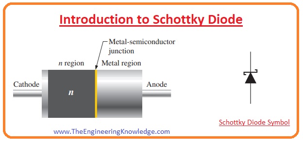
With this in mind, the similarity of the ITO/CdS/PbSe heterojunction with a Schottky diode suggests that the ohmic behavior initially obtained is due to the formation of a tunnel ohmic contact. Figure 8 a shows the suggested energy band diagram for this type of contact, which forms a very narrow potential barrier at the interface, thus allowing ... How does Schottky diode work? In a Schottky diode, a semiconductor-metal junction is formed between a semiconductor and a metal, thus creating a Schottky barrier. The N-type semiconductor acts as the cathode and the metal side acts as the anode of the diode. This Schottky barrier results in both a low forward voltage drop and very fast switching. This work presents a simplified analytical model of a p-n junction diode based on a graphene nanoribbon (GNR) and a unique type of Schottky diode based on metallic graphene and semi-conducting GNRs. The photocurrent generation process of the Au/n-GaSb Schottky PD is illustrated in Fig. 1 (a) with a band diagram. When the light with a shorter wavelength than the bandgap wavelength of the GaSb is absorbed in the active region of the PD, generated electron-hole pairs are converted tothe current.
Because only some of the cracks extend down to the i-layer, Schottky metals deposited on the surface will cover the p-type AlN and contact the i-layer forming cyclic Schottky diodes in the crack gaps separated by p-AlN/i-GaN:Be/n-type GaN:Ge diodes adjacent to the Schottky diodes.
Schottky Diode. In Schottky diodes, forward voltage is lower than that of other silicon P-N junction diodes. When there is a low current and voltage varies between 0.15 and 0.4 volts, drop in the voltage can be seen. In order to achieve that performance, these are constructed differently. Schottky diodes are widely used in rectifier applications.
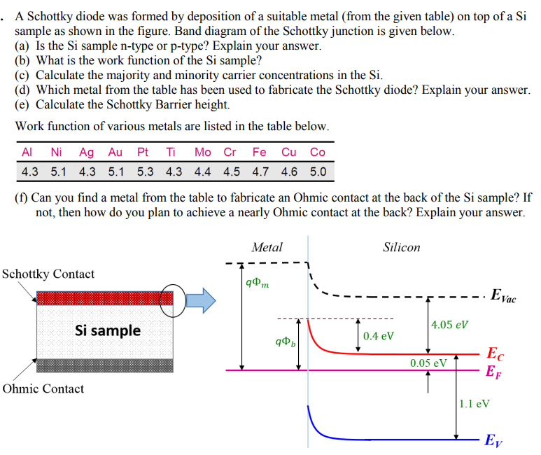
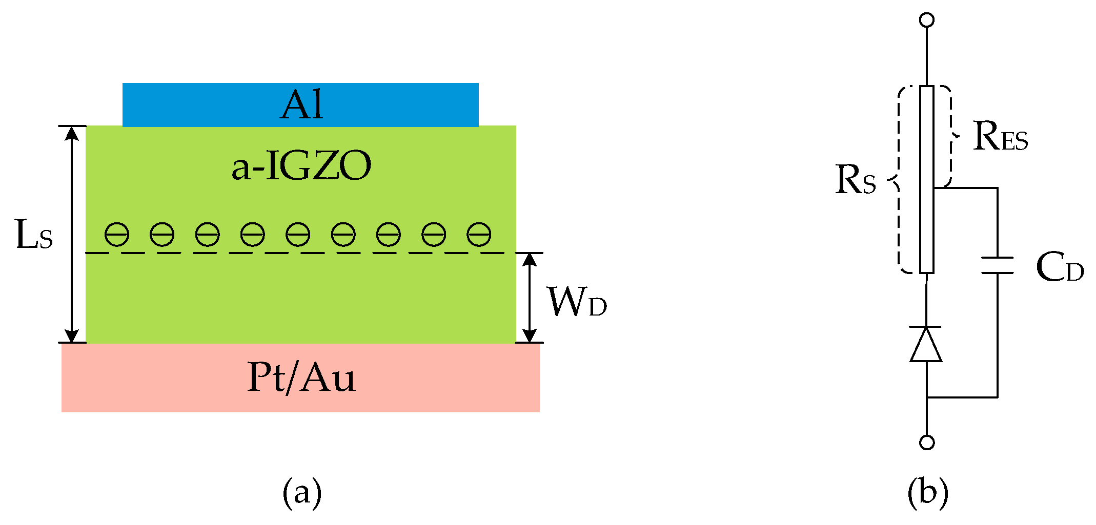
A Schottky diode is constructed with two metal conductors bonded to a doped semiconductor. One of the metal-semiconductor junctions is a Schottky contact, and the other metal-semiconductor junction is an Ohmic contact.
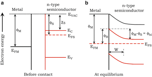
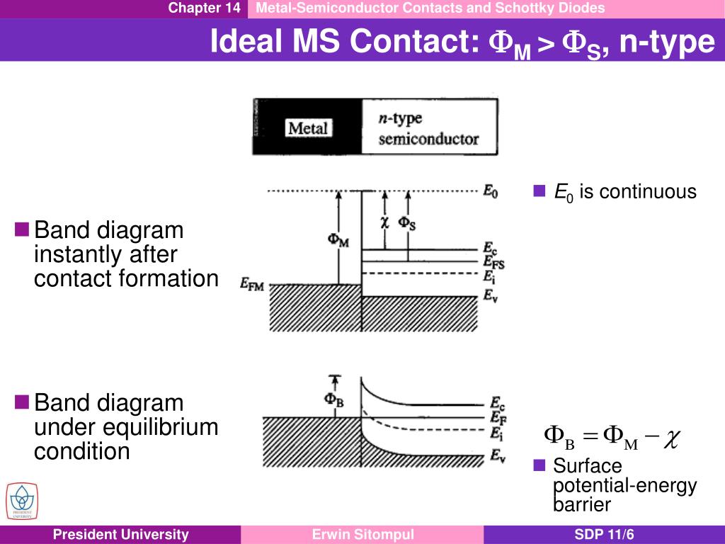
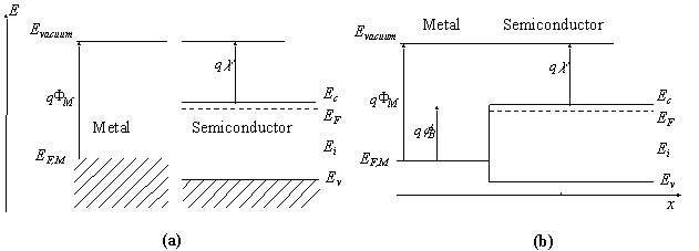
In graphene/Si Schottky diodes, the atomically thin and broadband transparent graphene forms a Schottky junction with Si, which allows the efficient exposure of the entire active diode area to light. ... Schematic band diagram of a metal-semiconductor junction, and b) a graphene-semiconductor (n-type) junction under zero bias condition.
Product Overview. The 1N5819RLG is an axial-lead Schottky Rectifier with epoxy moulded case. This series employs the Schottky barrier principle in a large area metal-to-silicon power diode. The state-of-the-art geometry features chrome barrier metal, epitaxial construction with oxide passivation and metal overlap contact.
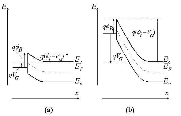
The Energy-band diagram versus voltage for the metal-semiconductor Junction shown in Fig.3 is very similar to these of the p-n junction. Because of similarity, we expect the current-voltage characteristics of the Schottky barrier junction to be similar to the exponential behavior of the p-n junction diode.
Why Does The Sic Schottky Barrier Diode Sbd Have A High Withstand Voltage Toshiba Electronic Devices Storage Corporation Americas United States
The mechanism of light emission in forward-biased and reverse-biased Schottky diodes is shown in Figure 1.4, which displays the band diagram of a metal-semiconductor junction under (a) equilibrium, (b) moderate forward bias, (c) strong forward bias conditions, and (d) under strong reverse bias where avalanche multiplication occurs.
A resistor restricts or limits the flow of electrical current. We will also recommend you to make circuit diagram symbols using the well-known software the EdrawMax. Schematic Symbols Diode Electronics Basics Electronics Circuit Circuit 5 Fire Alarm Circuit Using Germanium Diode. Diode circuit diagram symbols. The circuit diagram and. An electronic symbol is a pictogram […]
(a) Drawthe energy band diagram for an ideal metal/p-type semiconductor Schottky barrier diode and show that the barrier height for a metal/ptype semiconductor is given by (10.14). (b) Plot the energy band diagrams for an ideal metal/p-type semiconductor Schottky barrier diode for (i) fm > fs.
In this work, a metal-semiconductor diode in the form of Au/4H-SiC is fabricated, and the electrical properties of this device are systematically examined under dark and different illumination intensities. To perform this, the current-voltage (I-V) characteristics of the Schottky-type diode are analyzed at room temperature. The performance parameters such as saturation current ( $${I}_{0 ...
☑ Semiconductor Structures & Energy Band Diagram. ... We have different types of diodes such as solar cell, photodiode, light emitting diode, schottky diode and zener diodes and much more. Also different types of transistors like BJT, MOSFET and we will study different circuit applications such as clipper and clamper circuits, filtering ...
Advantages of Semiconductor. 1.Because of their dependability, compactness, and low cost, semiconductor devices are widely used in many applications. 2.A semiconductor is a distinct component that is utilised in optical sensors, power devices, light emitters, and solid-state lasers. 3.Electronic circuits made of semiconductor devices are simple ...
The formation of the p-n heterojunction diode with bipolar action was evidenced by comparing it with the Schottky junction. The energy band diagram of the p-n heterojunctions was predicted based on Anderson's rule. The staggered (type-II) band alignment with ΔE c = 3.5 eV and ΔE v = 2.9 eV was determined.
Different types of diodes have different voltage requirements. For Silicon Diodes, the forward voltage is 0.7V and for Germanium diodes, it is 0.3V. Usually, in Silicon Diodes, the dark band on one end of the diode indicates the Cathode terminal and the other terminal is anode.

Metal Semiconductor Metal Heterojunction Diodes Consisting Of A Thin Layer Of Crystal Silicon Applied Physics Letters Vol 102 No 9













0 Response to "41 schottky diode band diagram"
Post a Comment