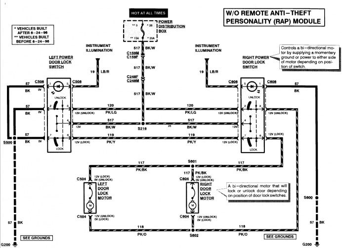
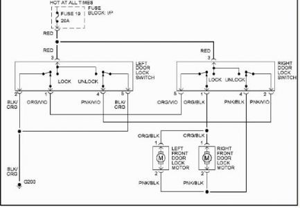
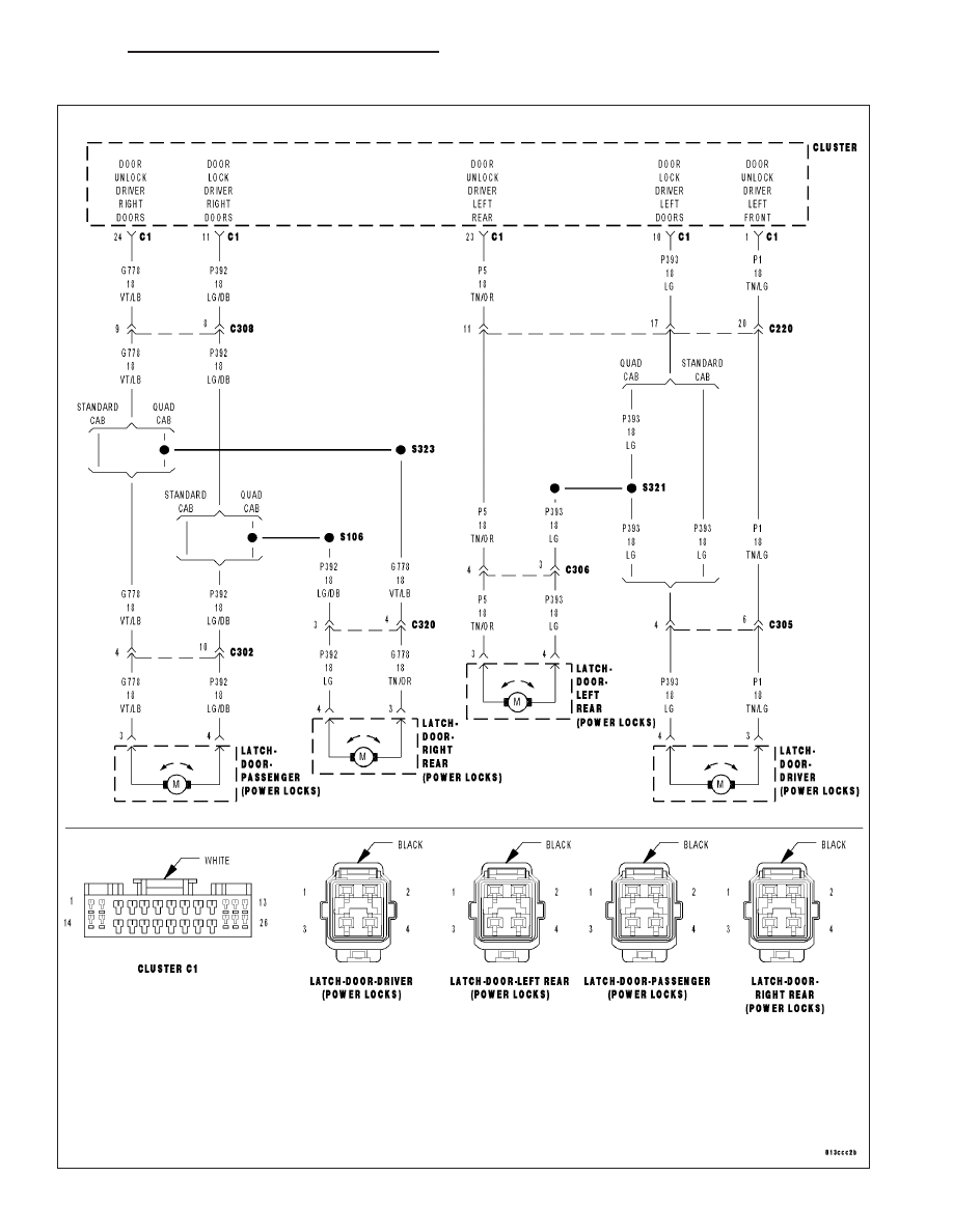
39 door lock actuator wiring diagram
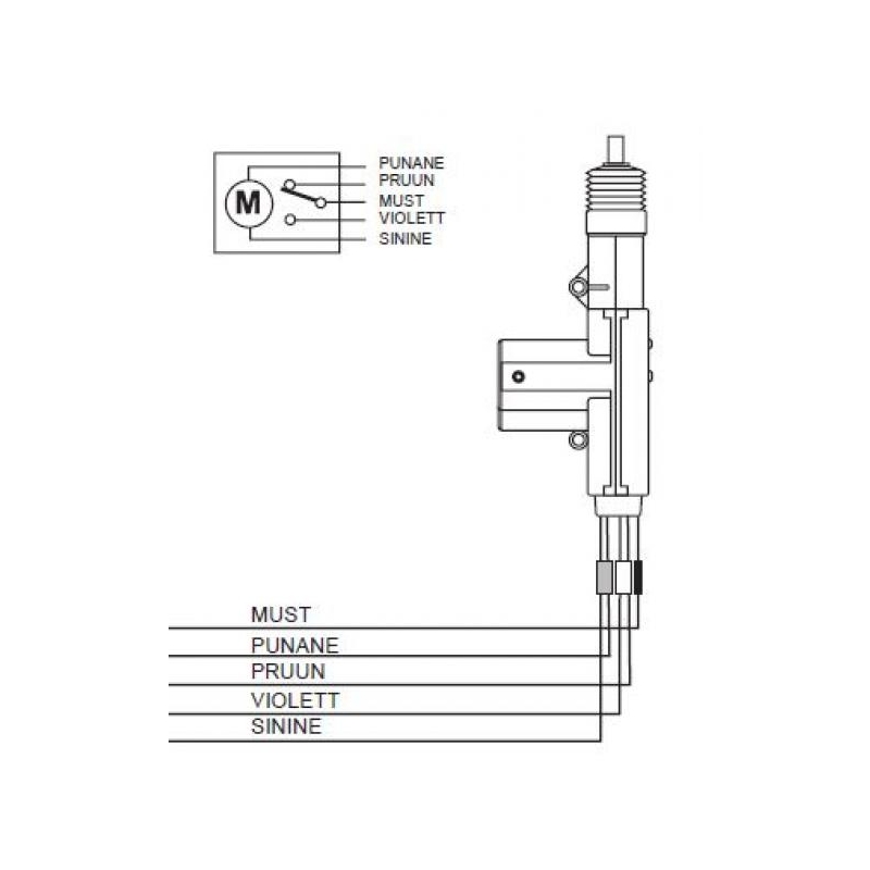
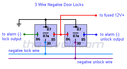
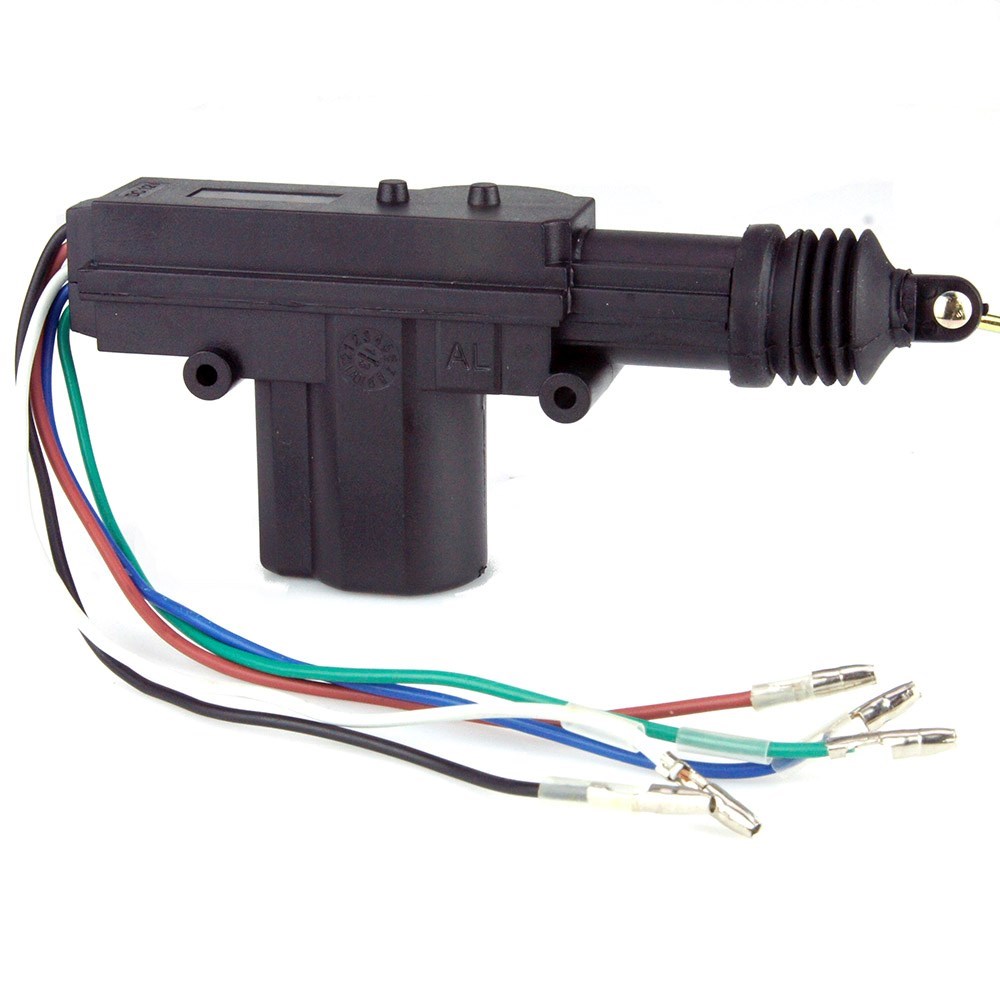
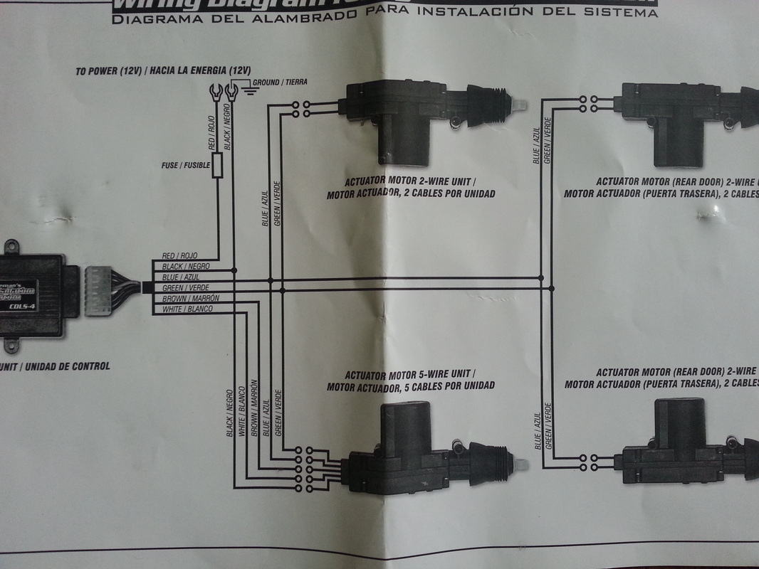
5 Wire Door Lock Actuator Wiring Diagram - wiring diagram is a simplified pleasing pictorial representation of an electrical circuit. It shows the components of the circuit as simplified shapes, and the power and signal associates in the company of the devices. A wiring diagram usually gives suggestion not quite the relative viewpoint and ... if you are doing a conversion from non power to power locks use the 5 wire to control the other locks. green lock, blue unlock. wire up the relays like your diagram and run it to the blue and green wire on the actuator. the actuator on the passenger door cut off the white brown and black wire and on the driver door ground the black wire and tie in the white and brown wire on the blue and green ...
ACTUATORS INSTALLATION 1. Remove door panels carefully 2. Install actuator in correct direction as shown in figures 1-a, 1-b and figure 2. Make sure that actuator will not block other moving parts inside of door (screen and its mechanism). Also make sure that actuator is moving parallel to door lock bolt. 3.

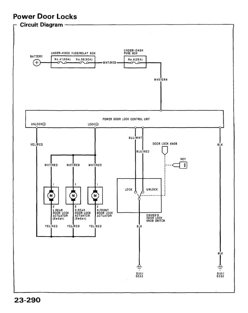
Door lock actuator wiring diagram
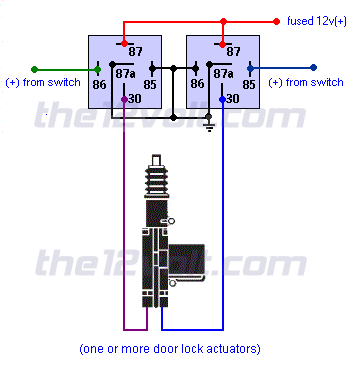
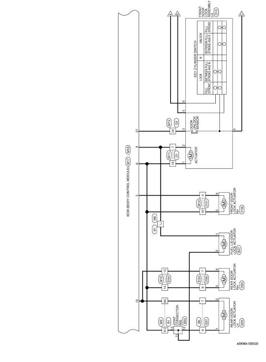
Door Locks - Actuators / Reverse Polarity - Positive Switch/Trigger (Type D) Relay Wiring Diagram. Both motor legs rest at ground at the relays. To lock or unlock the vehicle, polarity is changed on one motor leg via a positive pulse from a switch, alarm, keyless entry, etc. to the coil of the respective relay. Description: Door Lock Actuator Wire Diagram - Nissan Murano Forum with Door Lock Actuator Wiring Diagram, image size 634 X 619 px, and to view image details please click the image.. Here is a picture gallery about door lock actuator wiring diagram complete with the description of the image, please find the image you need. To diagnose, your mechanic may need to take the door cover off, check the door lock linkages and test the voltage at the door lock actuator, following the wire diagram. The voltage is measured when the power lock button is pressed. If there is a voltage, but the actuator doesn't work, the door lock actuator is bad and needs to be replaced.
Door lock actuator wiring diagram. Description: Car Alarm - Door Lock Wiring regarding Power Door Lock Actuator Wiring Diagram, image size 670 X 319 px, and to view image details please click the image.. Here is a picture gallery about power door lock actuator wiring diagram complete with the description of the image, please find the image you need. Universal Door Lock Actuator Wiring Diagram from static-cdn.imageservice.cloud. Effectively read a electrical wiring diagram, one has to find out how typically the components within the method operate. For example , if a module is usually powered up and it sends out a signal of 50 percent the voltage plus the technician will not know this, he'd ... Universal 5 Wire Door Lock Actuator Wiring Diagram Source: www.civic-eg.com READ Split Phase Motor Wiring Diagram Database Read cabling diagrams from unfavorable to positive plus redraw the signal being a straight collection. When the switch is closed, the green/white wire sends a signal to terminal 6 of the PSE, either from Green/red, or ground (brown). The PSE either sends vacuum or pressure to the door lock actuator. The green/red gets power from F4f11, so fuse 11 in the rear fuse box. Other wires at the switch are only for lighting.
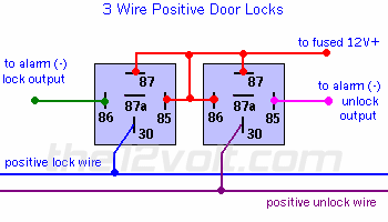
power door locks wikipedia. how to wire up a 5 wire door lock actuator relay from start to finish very easy how to wire up relays and install locks on vehicles that don t come with power door locks or does not offer any analog inputs to tap you outputs from you alarm remote start on to door 5 wire 5 wire actuator wiring diagram for wiring diagram database 5 wire actuator wiring diagram for 5 ... Power Door Locks & Wiring DiagramAmazon Printed Bookshttps://www.createspace.com/3623931Amazon Kindle Editionhttp://www.amazon.com/Automotive-Electronic-Diag... Results 97 - of Push Switch Blue LED Light Bar for Toyota Sequoia 4Runner Tundra Toyota . 2, sold Front Power Door Lock Switch Driver Side Left LH for . It is a 7 wire design and includes a wiring diagram. Order Toyota Tundra Door Lock Actuator online today. Free Same Day Store Pickup. 3 Wire Positive Door Locks: Type A and Type B are the most common types of door lock switch configurations found in most vehicles. In most cases you will not need to add relays for this type. Most of the newer alarms and keyless entries on the market today have both positive and negative (200 ma) door lock outputs that are usually capable of activating the factory relays.
Door Lock Actuators -----Trunk & Dome: Trunk Release Configurations -----Domelight Supervision ----- Technical Wiring Diagrams. View or Download PDF File. ATTENTION: This wiring information is being provided free of charge and on an "as is" basis, without any representation or warranty. ... December 23, 2018. 5 Wire Actuator Diagram . Actuator spring door actuator wiring 5 wire central locking actuator wiring diagram simple servo type direct acting diagrm pneumatic cylinder diagram pneumatic actuator diagram double acting actuator cutaway diagram 5 wire door lock actuator diagram 17.vancouvervisions.com. Lock the door then push the door actuator all the way down. Common wiring diagrams. Here s a power door lock wiring diagram for a 2009 chevrolet malibu. Attach the rod adapter to the actuators rod and tighten the screw figure 3. Data link connector circuit. Field measurement form. 5. Locate a safe position to mount the door lock actuator parallel to the factory door lock rod using the screws given (Figure 2). You can mount the actuator directly to the door, or use the bracket to cross a part of the door were there is no metal (Figure 2). In some cases, it is necessary to bend the actuator rod in order to reach the ...
92 95 Civic Coupe Door Lock Question Honda Tech Forum Discussion. Diagram actuator relay wiring central lock for aftermarket door locking 5 wire car builder technical diagrams power actuators work locks alternating 12 gt 121 installation guide auto heavy duty multiple systems 4pcs motor whole a spdt with harness 92 95 civic coupe question system alarm universal remote kit 1994 solenoid ...
I sent you the wiring diagram for the pins. Top two are for the motor, you switch polarity to spin motor forward and backwards using a DPDT switch. Lower left is 2wd indicator, lower middle is 4wd indicator, lower right is ground for the indicator pins. As far as indicator for 2/4wd I wired mine up to lights since I went prerunner to 4wd.
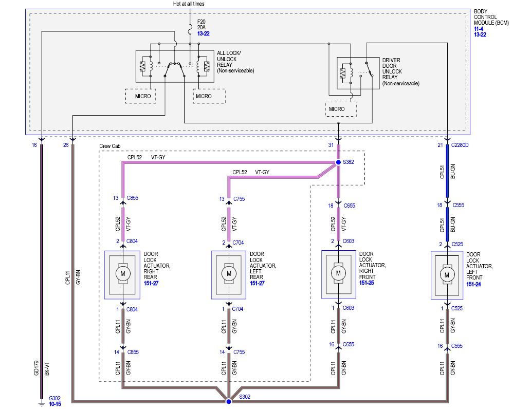
When the door lock relay (lock side) turns on (3), the front and rear door lock actuator motors perform a lock operation (4), and the. Source: repairguide.autozone.com How power lock doors work from wiring diagram and keyless remote please subscribe to my channel automotive electronics schematics by joseph for more.
From what I see there are two motors for whatever reason on the single driver door lock actuator. Try simply applying 12v at pins 1-5, 2-5, or 1-2 on component S47 (System Lock, Driver's Door). Try reversing polarity at each pin as well. I attached a Google image I found to try and give you a layout of where they are physically located.
This video will show you how to wire relays to control aftermarket door lock actuators.
Nissan Rogue Service Manual Wiring Diagram Without Intelligent Key System Door Lock Body Exterior Doors Roof Vehicle Security
Lock Actuator Wiring Diagram | Wiring Library - Power Door Lock Wiring Diagram. You can usually depend on Wiring Diagram as an important reference that can assist you to preserve money and time. Using the aid of the book, you are able to effortlessly do your personal wiring tasks.
Version. Listed below is the vehicle specific wiring diagram for your car alarm, remote starter or keyless entry installation into your 2004-2005 Dodge Ram . This information outlines the wires location, color and polarity to help you identify the proper connection spots in the vehicle. Please be sure to test all of your wires with a digital ...
View 26 Nippon Central Locking System Wiring Diagram. 3x New Universal Power Door Lock Actuator Motor 2 Wire 12 Volt 9 8lb Torque Usa Vehicle Electronics Gps Car Alarms Security. Car 4 Door Power Central Locking System Kit Control Conversion Lock Universal. Remote Keyless Entry For Car Central Lock Immobilizer Alarm Ke698 Eur 25 63 Picclick Fr.
Central Locking 5 Wire Door Lock Actuator Wiring Diagram from static-cdn.imageservice.cloud. To properly read a wiring diagram, one provides to learn how the particular components within the program operate. For instance , in case a module will be powered up and it also sends out the signal of fifty percent the voltage and the technician would ...
Power Door Lock Actuator Wiring Diagram. Find this Pin and more on House gate design by Masood Ghumro. Wire Switch. Door Switch. Jeep Doors. Car Door Lock. Three Way Switch. House Gate Design. Electrical Wiring Diagram.
12v Linear Actuator Wiring Diagram. Connect the T2 and T5 connectors to the linear actuator wires. on how to wire a 12V relay, but for now we will just focus on wiring the rocker switch. Take a look at our handy wiring diagram to see how to get this done. how to use relay boards to control the motion of linear actuators.
To diagnose, your mechanic may need to take the door cover off, check the door lock linkages and test the voltage at the door lock actuator, following the wire diagram. The voltage is measured when the power lock button is pressed. If there is a voltage, but the actuator doesn't work, the door lock actuator is bad and needs to be replaced.
Description: Door Lock Actuator Wire Diagram - Nissan Murano Forum with Door Lock Actuator Wiring Diagram, image size 634 X 619 px, and to view image details please click the image.. Here is a picture gallery about door lock actuator wiring diagram complete with the description of the image, please find the image you need.
Door Locks - Actuators / Reverse Polarity - Positive Switch/Trigger (Type D) Relay Wiring Diagram. Both motor legs rest at ground at the relays. To lock or unlock the vehicle, polarity is changed on one motor leg via a positive pulse from a switch, alarm, keyless entry, etc. to the coil of the respective relay.

Door Locks 5 Wire Alternating 12 Volts Positive Type C Relay Wiring Diagram Car Door Lock Electrical Circuit Diagram Door Lock System

Power Locks Just Dont Have The Power To Work 99 Chey Suburban If I Could Get The Wiring Diagram This Would Be Great

Door Locks Actuators Reverse Polarity Negative Switch Trigger Type D A Relay Wiring Diagram Door Lock System Relay Car Audio Installation








0 Response to "39 door lock actuator wiring diagram"
Post a Comment