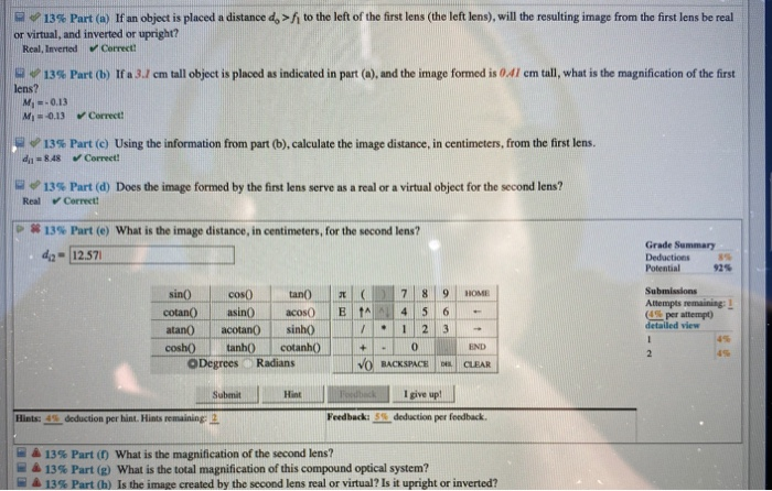
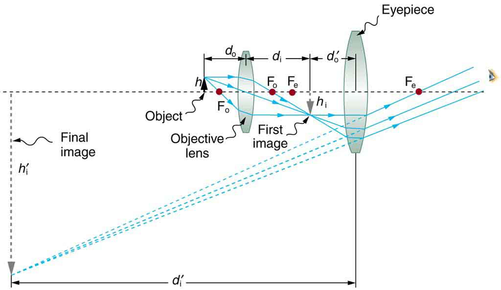
38 consider the compound optical system shown in the diagram
The arrow in the enthalpy diagram points from reactants to products. The direction of the arrow in an enthalpy diagram indicates whether a reaction is exothermic or endothermic. Enthalpy, H, increases up the y-axis. In an endothermic reaction, the reactants will be at the bottom of the enthalpy diagram. Question: (13%) Problem 8: Consider the compound optical system shown in the diagram, where two thin lenses of focal lengths 5.5 cm (left lens) and 6.5 cm ...
We make a two-lens optical system with spherical refractive surfaces that are close together, like a telescope. This optical system has a focal length of 1.0 to make things easier to calculate. The lens should have rays at low angles coming from an infinite conjugate, without spherical aberration and coma.
Consider the compound optical system shown in the diagram
The basic idea behind a Fresnel lens, which has the same optical properties as an ordinary lens, is shown in Figure 27-24, along with a photo of the LRLS. Suppose an object (a lightbulb in this case) is 17.1 cm behind a Fresnel lens, and that the corresponding image is a distance di = d in front of the lens. Question: (11%) Problem 8: Consider the compound optical system shown in the diagram, where two thin lenses of focal lengths 7.5 cm (left lens) and 4.5 cm (right lens) are separated by a distance 48 cm. > A 20% Part (a) If an object is placed a distance do = 15.4 cm to the left of the first lens (the left one) as shown in the figure, how far to ... Phase Diagram 3 For each of the questions on this worksheet, refer to the phase diagram for mysterious compound X: 1. What is the critical temperature of compound X? 2. If you were to have a bottle containing compound in your closet, what phase would it most likely be in? 3. At what temperature and pressure will all three phases coexist? 4.
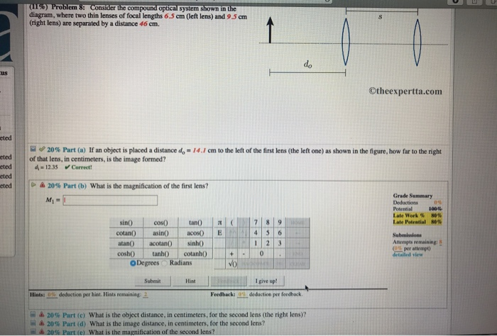
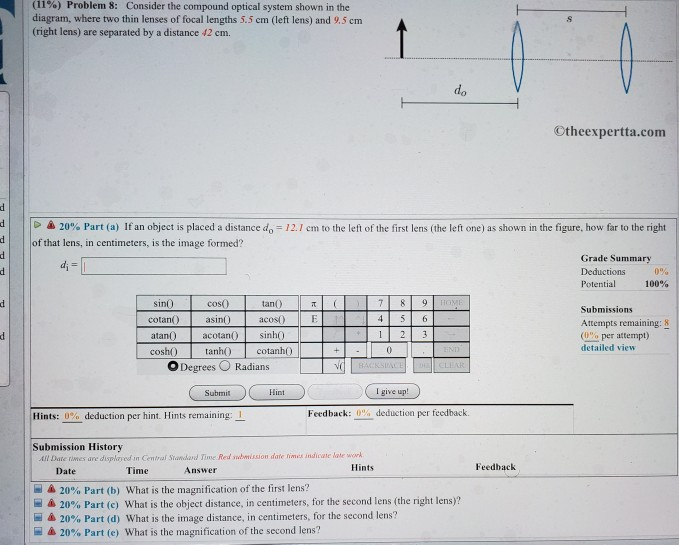
Consider the compound optical system shown in the diagram. The Human Eye as an Optical System Milton Katz Philip B. Kruger Introduction The eye is a compound optical system composed of a cornea and a lens shown in Figure 1. It is an adaptive optical system because the crystalline lens changes shape to focus light from objects at a large range of distances on… Question: (11%) Problem 8: Consider the compound optical system shown in the diagram, where two thin lenses of focal lengths 5.5 cm (left lens) and 9.5 cm ... Consider the phase diagram for carbon dioxide shown in as another example. The solid-liquid curve exhibits a positive slope, indicating that the melting point for CO 2 increases with pressure as it does for most substances (water being a notable exception as described previously). Notice that the triple point is well above 1 atm, indicating ... Consider the compound optical system shown in the diagram, where two thin lenses of focal lengths 9.5 cm (left lens) consider the compound optical system shown in the diagram, where two thin lenses of focal lengths 9.5 cm (left lens) and 42 cm (right lens) are separated by a distance 24 cm.
Transcribed image text: (11) Problem 8: Consider the compound optical system shown in the diagram, where two thin lenses of focal lengths 65 cm (left lens) ... The tracing of real rays through the surfaces of an optical system to determine the precise location and nature of the image is a complex computational task ... The above situation is shown in the upper diagram of figure 1 ... Now consider the lower diagram of figure 1.11 which shows a point in front of the lens referred to as the ... The following is an energy diagram for the conversion of A → B → C. The energies of activation and ∆H's for each step are also given. Calculate ∆H overall as shown on the energy diagram for A → B → C. system illustrated to the right below as an example, the basic method for discussed. As in Lessons 15, 16 and 17, the basic method is to draw a free body diagram of the forces involved, write an expression for the net force, and then solve for the acceleration. In a pulley system two masses are strung over a pulley. Note that downward
Consider the compound optical system shown in the diagram, where two thin lenses of focal lengths 7.5 cm (left lens) and 8.5 cm (right lens) are separated ...1 answer · 0 votes: a) using lens formula 1/f = 1/v - 1/u 1/7.5 = 1/ v + 1/15.3 v = 14.71 cm b) m1 = - v/u = - 14.71/15.3 = 0.9615 c) object distance for 2nd lens ... Nov 15, 2020 — Consider the compound optical system shown in the diagram, where two thin lenses of focal lengths 8.5 cm (left lens) and 5.5 cm (right lens) are ...1 answer · Top answer: As per the given question, focal length of the lenses are (f1)=8.5cm(f_1)=8.5cm(f1)=8.5cm f2=5.5cmf_2=5.5cmf2=5.5cm Distance between the lenses ... The V-diagram reveals that the largest shear force in the beam is -24 kN : segment CD The M-diagram reveals that the maximum bending moment is +48 kN·m : the 28-kN load at C. Note that at each concentrated force the V-diagram "jumps" by an amount equal to the force. There is a discontinuity in the slope of the M-diagram A lens is considered to be thin if its thickness t is much less than the radii of curvature of both surfaces, as shown in .In this case, the rays may be considered to bend once at the center of the lens. For the case drawn in the figure, light ray 1 is parallel to the optical axis, so the outgoing ray is bent once at the center of the lens and goes through the focal point.
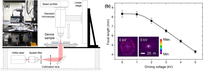
Monolithic Focus Tunable Lens Technology Enabled By Disk Type Dielectric Elastomer Actuators Scientific Reports
Compound Lens Example Charles A. DiMarzio Filename: twolens 3 October 2008 at 15:28 1 Thin Lens To better understand the concept of principal planes, we consider the com-pound lens of two elements shown in Figure 1. Initially, assume that we have designed this system assuming thin lenses. We can locate the image by applying the lens equation twice.

Scaling Capacity Of Fiber Optic Transmission Systems Via Silicon Photonics
Common Types of Trusses Bridge Trusses In particular, the Pratt, Howe,and Warren trusses are normally used for spans up to 61 m in length. The most common form is the Warren truss with verticals. For larger spans, a truss with a polygonal upper cord, such as the Parker truss, is used for some savings in material.
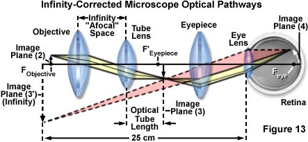
Microscope The Compound Microscope Britannica
The addition of bromine to 1,3-butadiene is an example. As shown below, a roughly 50:50 mixture of 3,4-dibromo-1-butene (the expected product) and 1,4-dibromo-2-butene (chiefly the trans-isomer) is obtained. The latter compound is remarkable in that the remaining double bond is found in a location where there was no double bond in the reactant.
Solved 11 Problem 9 Consider The Compound Optical System Chegg Com
Transcribed image text: (11%) Problem 9: Consider the compound optical system shown in the diagram, where two thin lenses of focal lengths 65 cm (left lens) ...
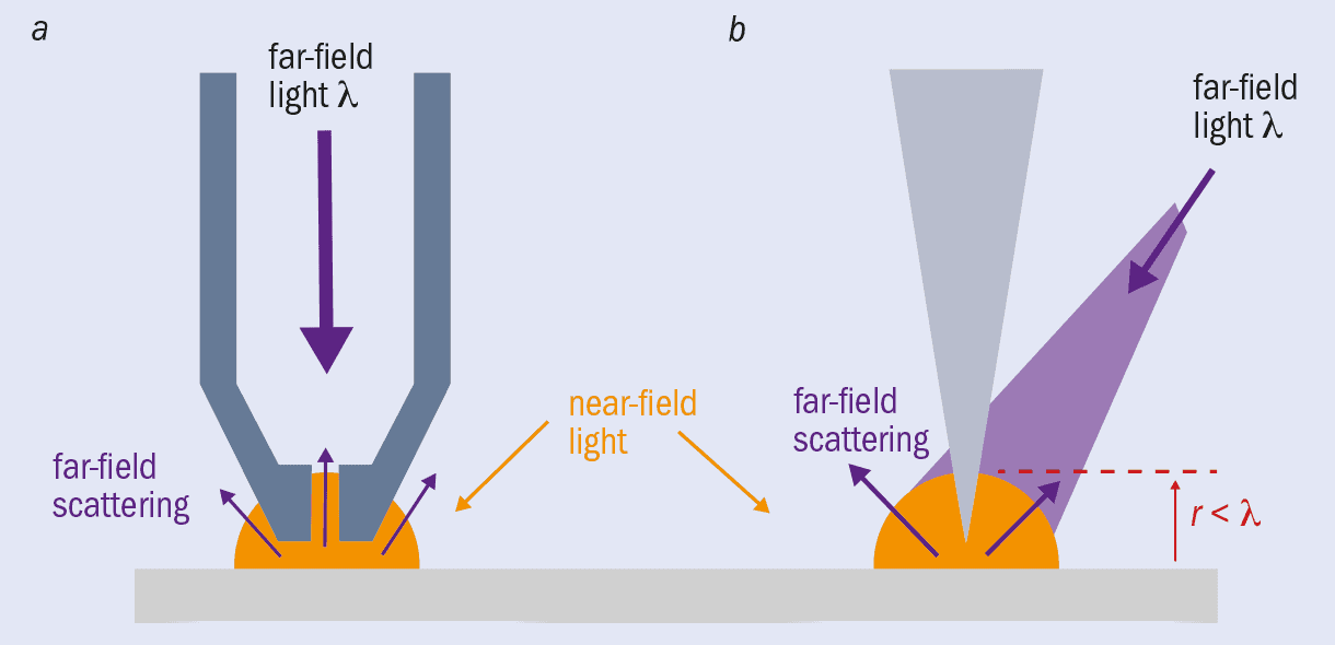
Optical Microscopy How Small Can It Go Physics World
s (6%) Problem 16: Consider the compound optical system shown in the diagram, where two thin lenses of focal lengths 6.5 cm (left lens) and 1.5 cm (right lens) are separated by a distance 31 cm. 1 do A 20 cm to the left of first lens (the left one) as shown in the figure, how far to the right (a) If an object is placed a distance do that lens, in.
Sensors Free Full Text Self Powered Sensors And Systems Based On Nanogenerators Html
The loading diagram for beam BE is shown in Fig. b. Beam FED. The only load this beam supports is the vertical reaction of beam BE at E, which is E y = 35.6 kN. The loading diagram for this beam is shown in Fig. c.
Microscope Optical Components Introduction Olympus Ls
The NCERT Solutions Class 12 Physics Chapter 9 Ray Optics and Optical Instruments is an important chapter of the Unit-Optics and is categorized under the latest term - II CBSE Syllabus 2021-22. Opting for the right reference material for this chapter is made easy with the NCERT Solutions for Class 12 provided here.
Answered Optics Optical Systems Geometrical Bartleby
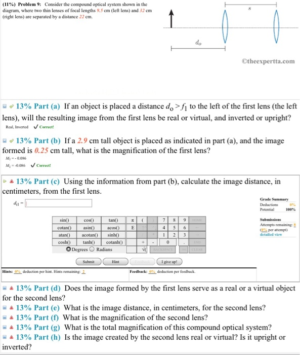
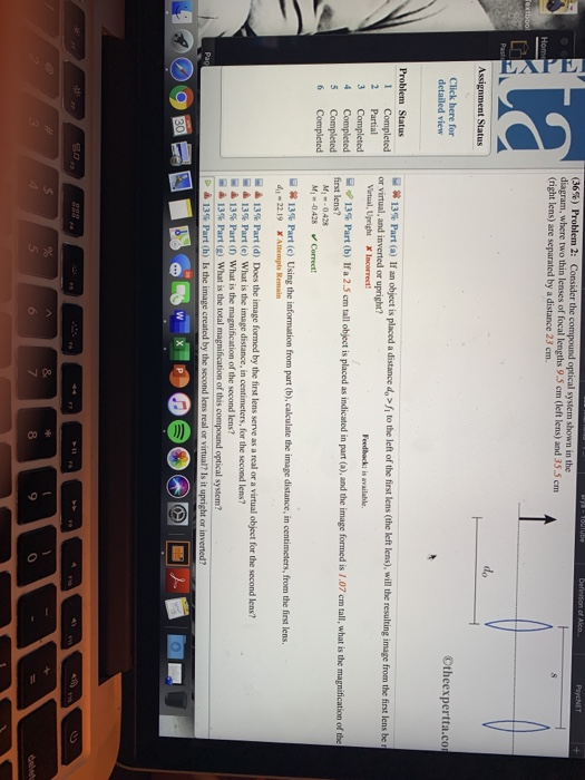
(11%) Problem 9: Consider the compound optical system shown in the diagram, where two thin lenses of focal lengths 9.5 cm (left lens) and 32 cm (right lens) are separated by a distance 22 cm. Otheexpertta.com 13% Part (a) If an object is placed a distance deſ to the left of the first lens (the left lens), will the resulting image from the first lens be real or virtual, and inverted or upright?
Solved 11 Problem 8 Consider The Compound Optical System Chegg Com
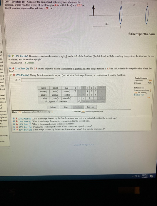
Nov 18, 2019 — Transcribed image text: (3% ) Problem 29: Consider the compound optical system shown in the diagram, where two thin lenses of focal lengths ...
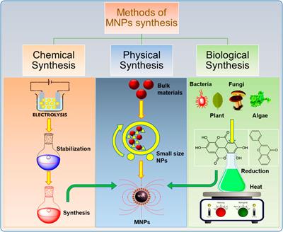
Frontiers Review On Recent Progress In Magnetic Nanoparticles Synthesis Characterization And Diverse Applications Chemistry
5.6 The diagram shows four states of a system, each with different internal energy, E. (a) Which of the states of the system has ... 5.10 The gas-phase reaction shown, between N2 and O2, was run ... 5.12 Consider the conversion of compound A into compound B: A ¡ B. For both compounds A and B, ∆Hf° 7 0. (a)
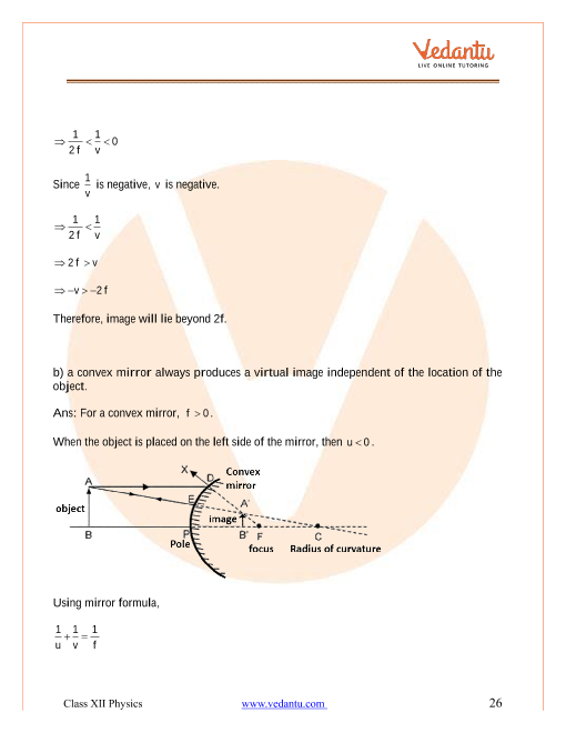
Ncert Solutions For Class 12 Physics Chapter 9 Ray Optics And Optical Instruments Free Pdf
EXAMPLE OF A SIMPLE OPTICAL SYSTEM† A system of two thin lenses is given as shown in Fig. 1. The left thin lens has a focal distance of f1 = 50mm (converging) and the right thin lens has a focal distance of f2 = 25mm (converging also). The two thin lenses are separated by 40mm. An object is placed at a distance of 75mm to the left of the left ...
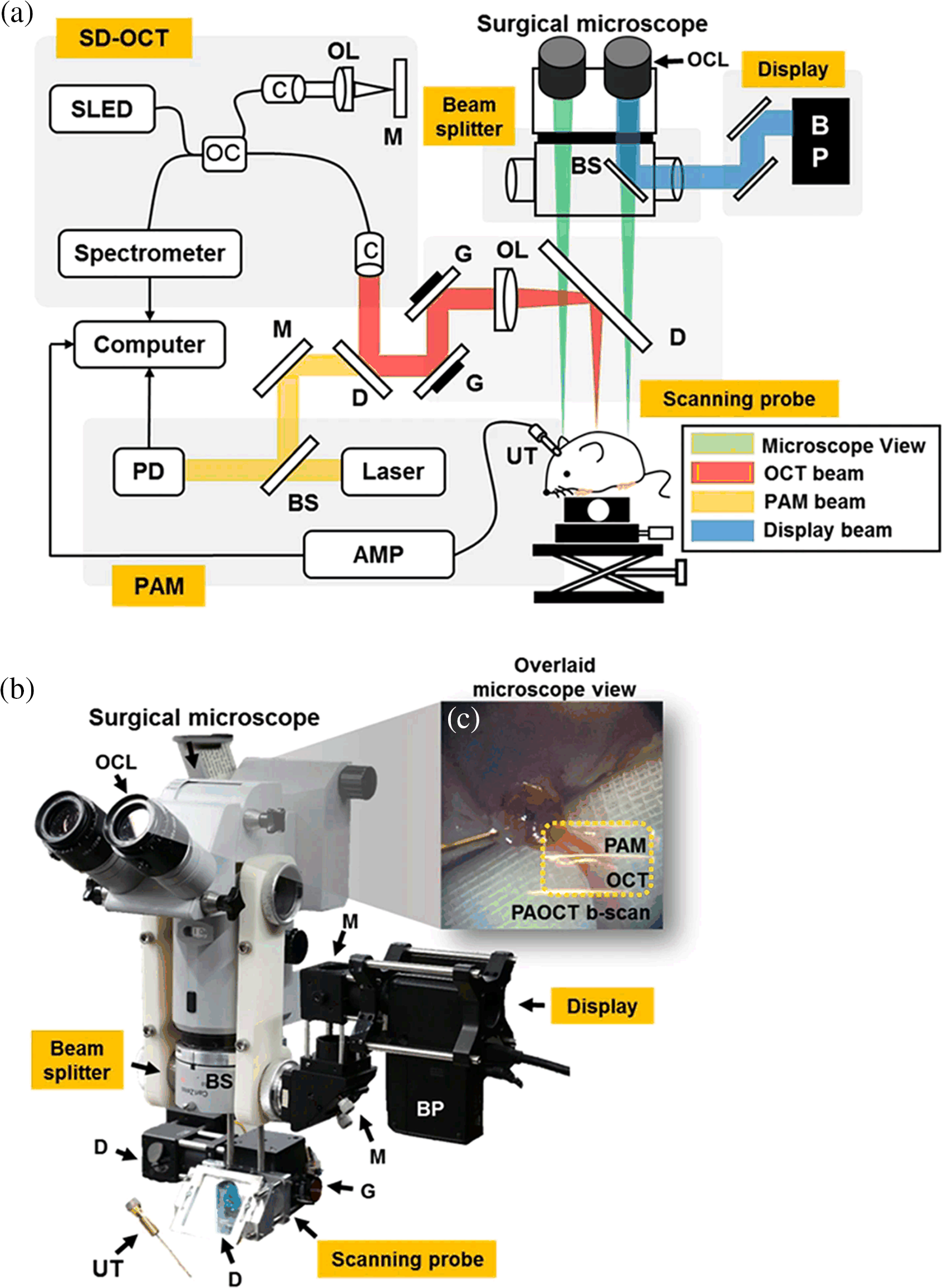
Comprehensive Review Of Surgical Microscopes Technology Development And Medical Applications
system • Phase diagram: Cu-Ni system. • System is:-- binary i.e. , 2 components: Cu and Ni.-- isomorphous i.e., complete solubility of one component in another; α phase field extends from 0 to 100 wt% Ni. Adapted from Fig. 9.4, Callister 7e. • Consider Co = 35 wt%Ni . Ex: Cooling in a Cu-Ni Binary 35 46 43 32 α: 43 wt% Ni L: 32 wt% Ni L ...
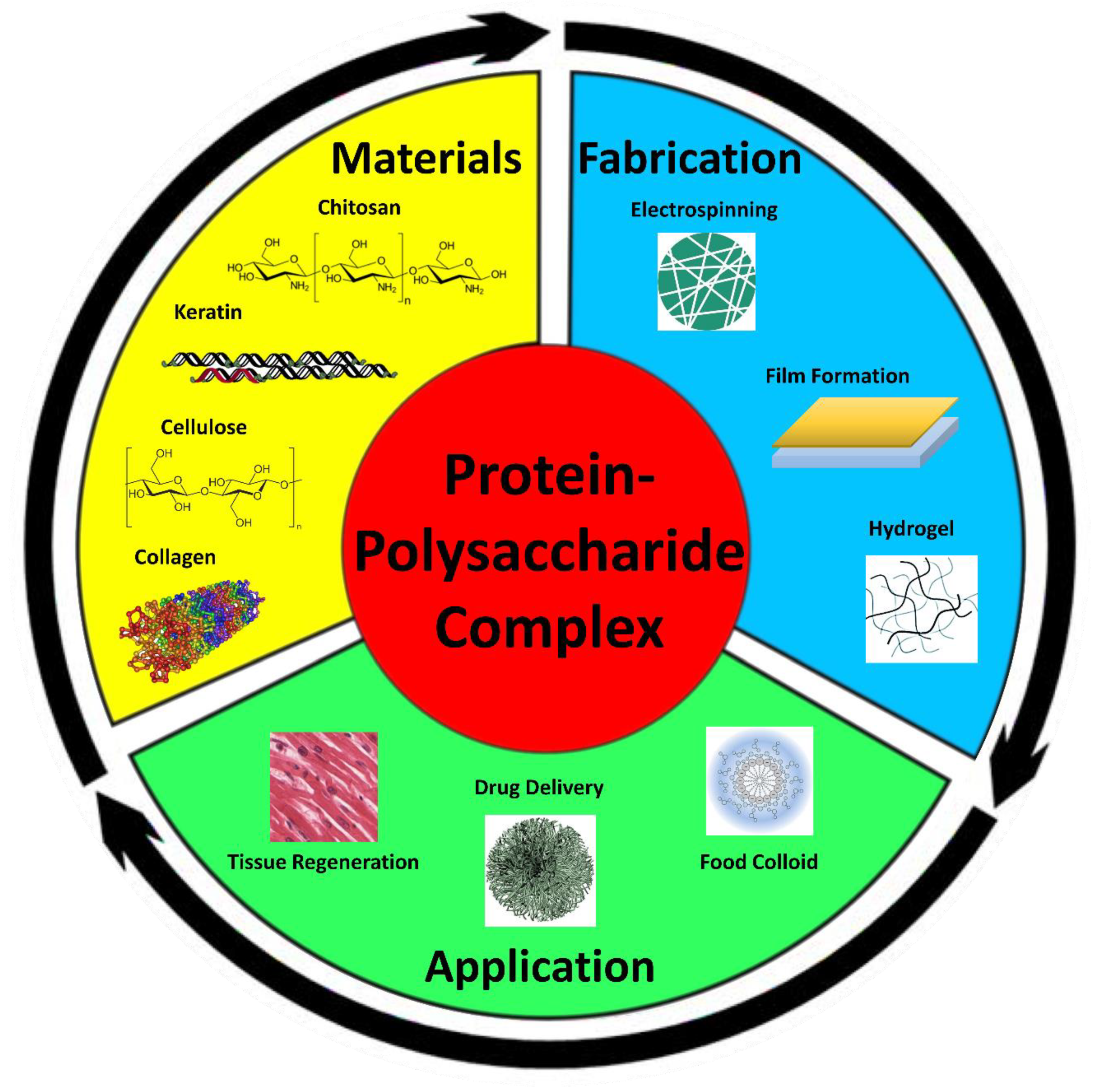
Polymers Free Full Text Protein Polysaccharide Composite Materials Fabrication And Applications Html
Congruently melting intermediates subdivide the binary system into smaller binary systems with all the characteristics of typical binary systems. • Intermediate compounds are especially common in ceramics, as the pure components may form unique molecules at intermediate ratios. Shown below is the example of the system MnO-Al 2O 3: 2000 1900 1800

Solar Concentrators An Overview Sciencedirect Topics
This question asked students to draw a correct Lewis electron-dot diagram for ethyne (C 2 H 2) in part (a). In part (b) students were asked to compare the C-C bond lengths in three given Lewis diagrams and the fourth diagram drawn for part (a). In part (c) students were given a Lewis diagram for ethanoic (acetic) acid and

Ascorbic Acid Hc6h7o6 Pubchem
consider the compound optical system shown in the diagram, where two thin lenses of focal lengths 9.5 cm (left lens) and 42 cm (right lens) are separa … ted by a distance 24 cm. Why do we have to determine the interval between the arrival time of P-wave and S-wave?
Solved 36 Problem 2 Consider The Compound Optical System Chegg Com
Physics questions and answers. (13%) Problem 8: Consider the compound optical system shown in the diagram, where two thin lenses of focal lengths 8.5 cm (left lens) and 9.5 cm (right lens) are separated by a distance 42 cm. s do ©theexpertta.com > * 20% Part (a) If an object is placed a distance do = 15.3 cm to the left of the first lens (the ...
Microscope Optical Components Introduction Olympus Ls
Consider the compound optical system shown in the diagram, where two thin lenses of focal lengths 8. 2. A student is getting her picture taken by a digital camera. The student is ho = 1.55 m tall and she ; 3. Suppose a book is held 5.8 cm from a 12-cm focal length lens. (a) Find the magnification of the im; 4.
Solved 3 Problem 29 Consider The Compound Optical Chegg Com
Consider the phase diagram for carbon dioxide shown in Figure 5 as another example. The solid-liquid curve exhibits a positive slope, indicating that the melting point for CO 2 increases with pressure as it does for most substances (water being a notable exception as described previously). Notice that the triple point is well above 1 atm, indicating that carbon dioxide cannot exist as a liquid ...
Nhess Recent
Phase Diagram 3 For each of the questions on this worksheet, refer to the phase diagram for mysterious compound X: 1. What is the critical temperature of compound X? 2. If you were to have a bottle containing compound in your closet, what phase would it most likely be in? 3. At what temperature and pressure will all three phases coexist? 4.

3 Consider The Compound Optical System Shown In The Diagram Where Two Thin Lenses Of Focal Homeworklib
Question: (11%) Problem 8: Consider the compound optical system shown in the diagram, where two thin lenses of focal lengths 7.5 cm (left lens) and 4.5 cm (right lens) are separated by a distance 48 cm. > A 20% Part (a) If an object is placed a distance do = 15.4 cm to the left of the first lens (the left one) as shown in the figure, how far to ...

Pearl Wikipedia
The basic idea behind a Fresnel lens, which has the same optical properties as an ordinary lens, is shown in Figure 27-24, along with a photo of the LRLS. Suppose an object (a lightbulb in this case) is 17.1 cm behind a Fresnel lens, and that the corresponding image is a distance di = d in front of the lens.
Calibration Method For The Electrically Tunable Lens Based On Shape Changing Polymer

Microscopic Origins Of The Crystallographically Preferred Growth In Evaporation Induced Colloidal Crystals Pnas
Solved 11 Problem 8 Consider The Compound Optical System Chegg Com

An Introduction To The Light Microscope Light Microscopy Techniques And Applications Technology Networks

Progress In Heat Transfer Research For High Temperature Solar Thermal Applications Sciencedirect

Dc Motor Tutorial Motor Calculations For Coreless Brush Dc Motors
Solved 1 Dalilula 12 01 Uu Dul Dalili Ibu Dauc 12 Juli Juu Chegg Com
Microscopes Physics Ii

Microscopic Fringe Projection Profilometry A Review Sciencedirect

Johannes Knolle S Research Works Imperial College London London Imperial And Other Places
Low Cost Optical Mapping Systems For Panoramic Imaging Of Complex Arrhythmias And Drug Action In Translational Heart Models Scientific Reports

An Extensive Review Of Various Technologies For Enhancing The Thermal And Optical Performances Of Parabolic Trough Collectors Abed 2020 International Journal Of Energy Research Wiley Online Library

Understanding Waveplates And Retarders Edmund Optics
Hans Lippershey Dutch Inventor Britannica

Pdf Topical Review Applications Of Magnetic Nanoparticles In Biomedicine
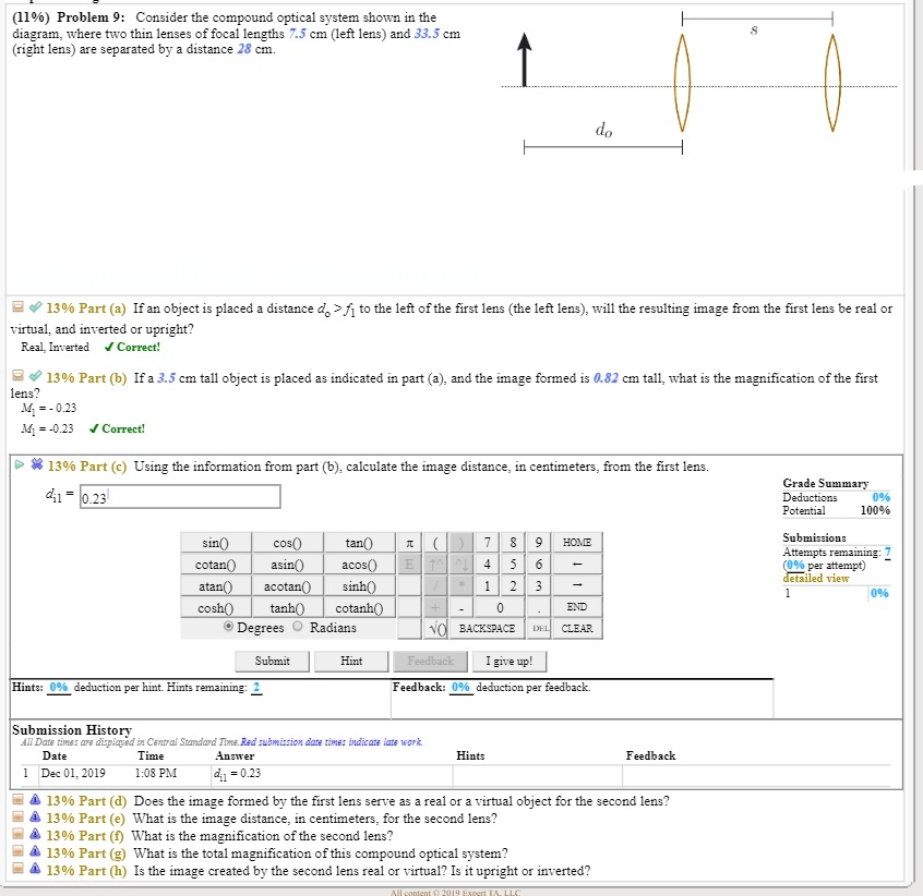
Solved 1190 Problem 9 Consider The Compound Optical Vystem Shown Ir The Diagram Where Two Thin Lenses Of Fccal Length Cm Left Ler Ad 33 5 Cr Rignt Len Are Eparated By Distance 28

16 3 Lenses Texas Gateway
0 Response to "38 consider the compound optical system shown in the diagram"
Post a Comment