37 request to exit wiring diagram
Dec 18, 2019 · Wiring a Relay Module to the ESP32. Connect the relay module to the ESP32 as shown in the following diagram. The diagram shows wiring for a 2-channel relay module, wiring a different number of channels is similar. Warning: in this example, we’re dealing with mains voltage. Misuse can result in serious injuries. SECURITRON EEB2, EEB3N EXIT BUTTON WITH INTEGRATED TIMER INSTALLATION AND OPERATING INSTRUCTIONS DESCRIPTION Model EEB2 is a two-inch square, exit button, mounted on a stainless steel (S.S.), single gang key plate. Model EEB3N is a rectangular exit button, mounted on a 1 3/4" S.S. narrow stile key plate. Both EEB2 and EEB3N have a 3A switching
Sketch A – “Typical Underwater Exit Design” with Muffler AFT of Exit Sketch B – Custom “twin outlet” lift muffler can be used when the existing main exhaust run is too small and cannot be upgraded easily – With a 5-6″ inlet and two smaller outlets ( 3.5″ – 4.5″) this base design can safely be used in applications up to 400 ...

Request to exit wiring diagram
Wiring. The basic hook-up consists of the REX (Request to Exit) device, a power supply, and a maglock. When the REX sees motion, power is removed from the maglock. Request To Exit PIR sensors Installation Instructions 1.0 Description The DS160/161 is a passive-infrared (PIR) detector designed for request to exit (REX) interior applications. ... the wiring through the trim plate and into the base before mounting the base and trim plate onto a single gang electrical box. Magnetic Lock Wiring Diagram Much like the door access control system diagram above, the mag lock wiring diagram relies on a few simple basics: electricity supply, switches, and, of course, locks. Magnetic locks , also referred to as mag locks or maglocks for short, rely on a constant flow of electricity to stay sealed.
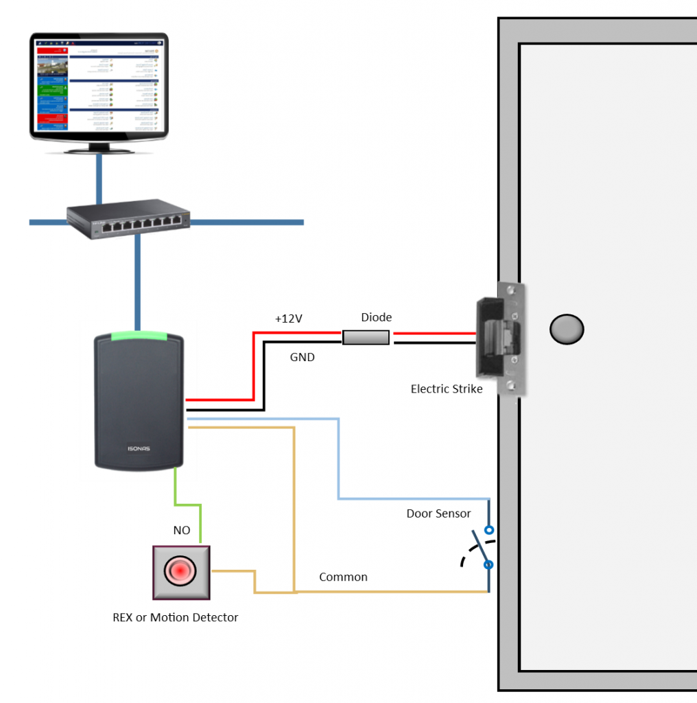
Request to exit wiring diagram. Wiring diagram The diagram below shows how to wire 8KW and 9KW electri˜ed locks. Figure 1—Wiring diagram for 8KW and 9KW electri˜ed locks (9KW with RQE shown) Run wires through the door or mount wires to the door sur-face with wire molding. To ˜nd the correct wire gauge for wire runs, see Figure 2 on the reverse side. RQE (Request-to-exit ... These instructions cover installing and wiring remote options to the AL- 80 Series Alarmed Exit Device using the 546 wiring harness. Refer to instruction A7224B for additional instructions. Remote options include Remote Power, Remote Monitor, Request to Exit (REX), Door Status and Remote Reset. In addition, there are field selectable options: A crucial step in setting up your push-to-exit button is properly wiring all the components. In an IP system like Kisi, this will involve the door lock, the access reader, the controller, the power supply, and the push-to-exit button (as well as optional contact sensors). The following diagram outlines the setup with an electric strike lock. Instructions for wiring a VP1 reader-controller with a Request-to-Exit device. Instructions for wiring a VP1 reader-controller with a Request-to-Exit device.
LocksOnline Wiring Diagram 004. Oct 30, · Request to Exit Wiring Diagram ds ds installation guide high performance request to 3 3 8 disabling the request to exit the ds can be disabled by using terminal r and an external device such as an access control or burglar alarm system. Push Buttons. The TS-2 request to exit station, with square push button, provides a convenient way to add authorized access control to a variety of applications. Features. Standard Features. Switch mounted on single gang wall plate with 430 stainless steel finish; T.REX-LT-NL T.Rex request-to-exit detector with tamper and timer, white (unbranded) TREX-LT2 T.Rex request-to-exit detector with tamper, timer and 2 relays, white T.REX-LT2-NL T.Rex request-to-exit detector with tamper, timer and 2 relays, white (unbranded) T.REX-XL T.Rex request-to-exit detector with tamper, piezoelectric buzzer and timer, white Terminals are entry and exit ports that exchange information between the front panel and block diagram. They are analogous to parameters and constants in text-based programming languages. Types of terminals include control or indicator terminals and node terminals.
Request-to-Exit solutions can be used to manage accessibility within secure areas. BEA has a complete line of request-to-exit (REX) products including sensors, locking devices, push buttons and keypads. Building codes often require two forms of exit devices on a door, such as a motion sensor and a push button, to ensure that occupants are ... Wiring Diagram: Installation: 1. Run four wires through the wall to a single-gang or slimline back-box. 2. Connect the four wires from the back-box to the Request-to-Exit Sensor according the Wiring Diagram above. 3. Screw the plate into the back-box, taking care not to crimp the wires. 4. Remove clear protective film from the sensor before use. You can also request a free revision, if there are only slight inconsistencies in your order. Your writer will make the necessary amendments free of charge. You can find out more information by visiting our revision policy and money-back guarantee pages, or by contacting our support team via online chat or phone. Class vs. type. In casual use, people often refer to the "class" of an object, but narrowly speaking objects have type: the interface, namely the types of member variables, the signatures of member functions (methods), and properties these satisfy.
Wiring A Maglock With A Rex Device Prodatakey Inc
positive input wire of a magnetic lock. Note that another switching device such as a motion detector can be put between the white wire and the source of +V (as is shown in Figure 1). Figure 2 shows the internal schematic of the push button contacts and timer which helps clarify the unusual wiring method needed to maintain double break safety.

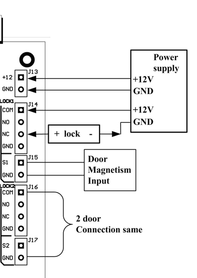
S3150 Entrypass Corporation
T. Rex Exit Detector The T-Rex is a sophisticated and cost-effective request to exit device for all access control applications and an alternative to installing an exit button. Outstanding innovations such as X-Y Targeting and Digital Signal Processing (DSP) implementation make the T.Rex the fastest and most reliable exit detector on the market.
Door Wiring Diagrams
RCR-REX Request-to-Exit Dual Technology Motion Sensor Installation Instructions 2 Wiring This section provides examples of different wiring options. The options are all shown in the fail safe mode. Basic hook-up Figure 4 shows the basic hook-up for the RCR-REX, a power supply and a magnetic lock. When the sensor sees motion, power

Wiring And Configuring A Rex Device Prodatakey Inc
The L-Series switched to a handed modular three-wire request to exit (RX) switch.This change was originally completed on electrified locks in October 2014. The RX switch will have a molex connector attached re quiring use of Allegion Connect Harnesses and IVES hinges, or connector can be snipped off and traditional splicing methods employed to wire lock.
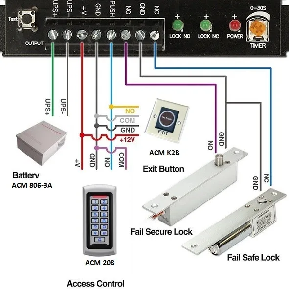
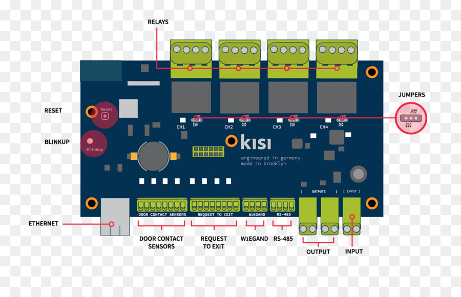
How To Wire An Access Control Board
DS150i/DS151i Installation Guide Request-to-Exit PIR Detectors 1.0 Description The DS150i is a passive-infrared detector designed for request to exit (REX) applications. It is UL Listed as an access control device under the UL 294 standard and is listed for Class I for UL Canada (ULC-S319). For

External Power Supply Fail Safe Electric Lock With Rex Motion Sensor Kisi Support
The single gang TS-7 and narrow stile TS-9 request to exit stations, with rectangular push button, provide a convenient way to add authorized access control for a variety of applications. TS-7 and TS-9 are available with timer relay for applications that require door to remain unlocked for a specified time.
Grandstream Com
- WIRING INSTRUCTIONS— Magnetic lock or fail safe strike with button, keypad, maintained button and remote receiver. wired in series Power Supply for fail safe strikes and magnetic locks should be DC. If this is not available you may use an AC power source and wire inline a "Full Wave Bridge" rectifier. This will conver t the AC to DC.
Acm N40 Sensore A Infrarossi Touchless Controllo Accessi Pulsante Di Uscita Apertura Porta Non Touch China Rfid Manufacturer China Rfid Cards Factory Rfid Tag Nfc Tag Rfid Wristband Rfid Reader Factory Uhf Reader
About Press Copyright Contact us Creators Advertise Developers Terms Privacy Policy & Safety How YouTube works Test new features Press Copyright Contact us Creators ...
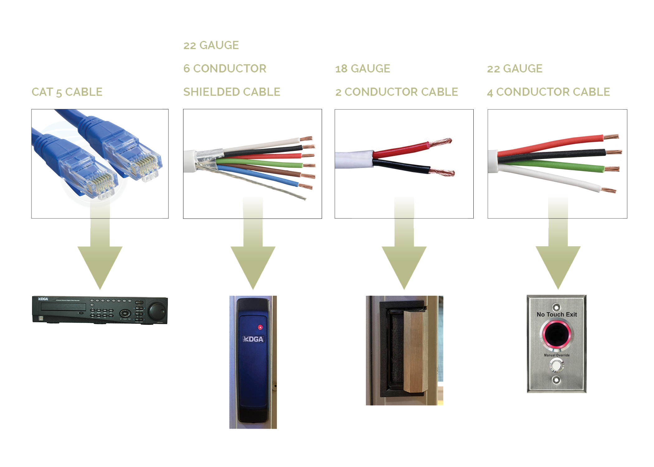
Access Control System Avoid Common Cable Wiring Mistakes
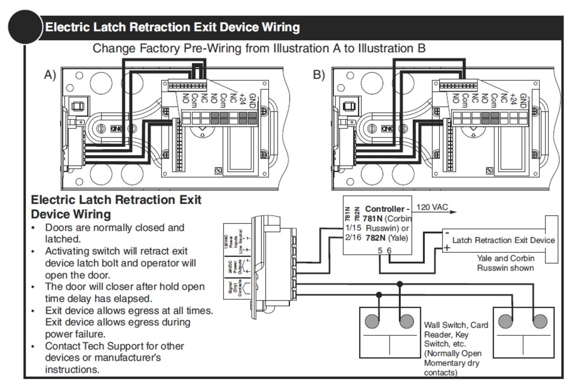
56- Electric Latch Retraction Exit Devices Installation and Wiring Instructions With Optional 53- Latchbolt; 55- Request to Exit; and TL- (SARGuide) Connection Instructions FOR INSTALLATION ASSISTANCE CONTACT SARGENT • 1-800-810-WIRE (9473) • www.sargentlock.com SECTION I: OVERVIEW 1. Description
Uncw Edu
The following common wiring diagrams are available: One Single Door with Panic Bar. Electric Latch Retraction, with Auto Operator ... riser diagrams falcon exit devices ... wiring diagram request form . Common Wiring diagrams . wiring diagram for QEL panics ...
How To Coordinate Automatic Doors With Locking Devices Dengarden
55- Signal Switch (Request to EXIT) The signal switch monitors the touch bar. Touch bar monitoring may be used to detect egress, sound an alarm, send a signal to a remote location, or de-energize an electromagnetic lock. Ordered as 55 Prefix. FEATURES.

How To Install A Push To Exit Button
Option RX (Request to Exit), LX (Latchbolt Monitor), DPS (Door Position Sensor, available non-deadbolt models), DM (Deadbolt Monitor, available deadbolt models). See pricebook for additional lock options. Note: Messaging indicators are not available for the L909x Series L Series mortise indicators Function + cylinder Trim Finish Handing Option code
China 12v Magnetic Door Lock Embedded Installation For Access Control System On Global Sources Magnetic Lock Em Lock Electromagnetic Lock
Wire sizes recommended for Wiegand interface (4-conductor) are as follows: Distance Size Up to 200 ft 22 gauge Up to 300 ft 20 gauge Up to 500 ft 18 gauge 1. Below is the standard wiring for most HID proximity card readers and keypads. 2. Find the specific wiring configuration for your Wiegand reader or keypad in the documents that came
1
Product Features. Passive Infrared Request to Exit Device. Designed to reliably release magnetic locks. Automatically cuts power to the lock, allowing the individual to exit without even realizing that the door is secured. Request to Exit (REX) output. Easily adjustable beam pattern.
Door Wiring Diagrams
Wiring Tool. Use the Wiring tool to wire objects together on the block diagram. For example, in Figure 7, the Wiring tool wires the Number of Measurements terminal to the count terminal of the For Loop. When the mouse hovers over the exit or entry point of a terminal or over a wire, the cursor automatically accesses the Wiring tool. Figure 7.
Access Control System Avoid Common Cable Wiring Mistakes
Paxton exit button - E50. Part No: 356-310. Quick ref: 0217770. Login or register to see prices. In Stock.
12sa550 Stand Alone Door Controller With I O Relay Module User Manual Iopass Book Tysafety Products Kantech
ENFORCER Outdoor Piezoelectric Request to Exit Pushbutton -LARM U.S.A., Inc 3SECO Wiring the Manual Override: SD-6176-SSVQ and SD-6276-SSVQ Only Connect the manual override button with the included wires. Notes a. Remove the thin panel on the bottom of the plastic cover to allow wiring to pass through. b.
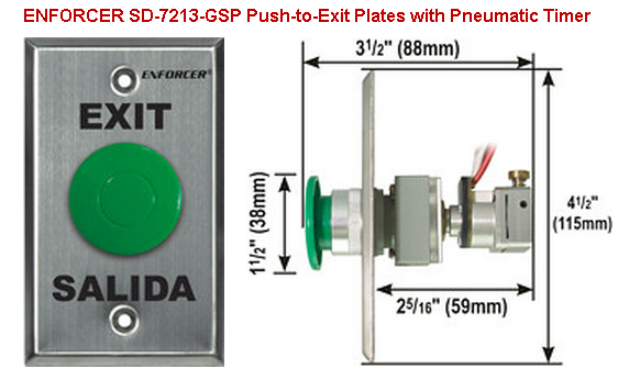
Seco Larm Sd 7213 Gsp Request To Exit Plates With Pneumatic Timer Pam Distributing Co
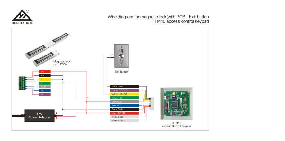
Magnetic Lock Wiring Diagram Much like the door access control system diagram above, the mag lock wiring diagram relies on a few simple basics: electricity supply, switches, and, of course, locks. Magnetic locks , also referred to as mag locks or maglocks for short, rely on a constant flow of electricity to stay sealed.

Amazon Com Obo Hands Fail Safe Electric Magnetic Lock 180kg 350lbs Holding Force For Door Access Control System Electromagnet Nc Mode Industrial Scientific
Request To Exit PIR sensors Installation Instructions 1.0 Description The DS160/161 is a passive-infrared (PIR) detector designed for request to exit (REX) interior applications. ... the wiring through the trim plate and into the base before mounting the base and trim plate onto a single gang electrical box.

Proximit Installation Electronic Security Engineering
Wiring. The basic hook-up consists of the REX (Request to Exit) device, a power supply, and a maglock. When the REX sees motion, power is removed from the maglock.
Uncw Edu
Door Wiring Diagrams

Vis 7028 Indoor Stainless Steel No Touch Infrared Request To Exit Button With Time Delay Slim Size Led Light Nc Com And No Outputs Visionis
Objects Eanixter Com
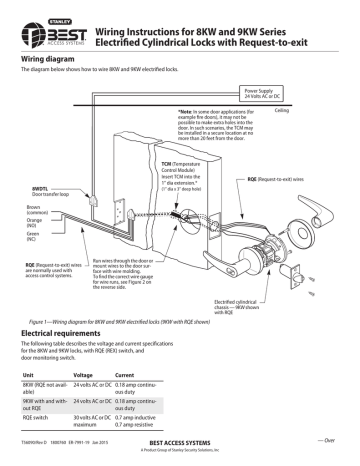
Installation Instructions For The 8kw And 9kw Electrified Cylindrical With Rqe Manualzz
How To Wire Your Door Access Control System Kintronics
Uncw Edu
Hidglobal Com

Amazon Com Aleko Lm157 Exit Sensor Underground Automatic Gate Opener Exit Wand Loop Car Detector Tools Home Improvement
Honda Diagram Pengkabelan Kabel Listrik Kabel Gambar Png

How To Install A Push To Exit Button

Visionis Vis 7000 Indoor Green Square Request To Exit Button For Door Access Control With Led Light Nc C And No Outputs Amazon Com
Access Control Wiring Help Needed R Accesscontrol

Locksonline Wiring Diagram 004 Locks Online
Resources Boschsecurity Cdn Azureedge Net
Nortekcontrol Com
Security Honeywell Com
0 Response to "37 request to exit wiring diagram"
Post a Comment