37 msd rpm activated switch wiring diagram
MSD’s RPM-Activated Switch allows you to control accessories based on engine RPM. The RPM-Activated Switch has two outputs – one to turn accessories on by su... Kit Contains: 4 - 1/4 Flat Washers 4 - 1/4 Lock Washers 4 - 1/4 - 20 x 3/4 Bolts 4 - 1/4 x 20 Nuts 1 - Solenoid 1 - 30 AMP Fuse 1 - 90 degree mount bracket In most cases, the MSD RPM Activated Switch is a good choice for triggering this shifter. If you use another brand, follow their instructions for installation. 1. Attach Solenoid to shifter. 2. Place relay and RPM Activated Switch in ...
Msd pro mag 12lt wiring diagram. Figure 7 wiring an rpm activated switch. This relay is designed to be used with the msd pro mag 44 in conjunction with a kill switch. From pro mag generator. Today msd is developing electronics for your entire powertrain. Msd Ignition 12 Amp Electronic Points Box Msd8106 For Msd Pro Mag 12 12lt Msd Ignition.
Msd rpm activated switch wiring diagram
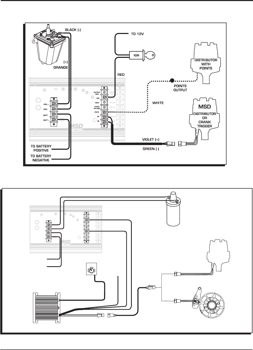
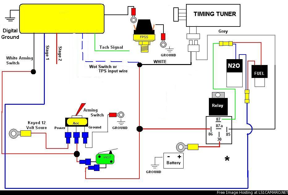
This Switch will supply then remove ground to a circuit. These RPM-Activated Switches will perform a variety of different functions from turning on a bulb or solenoid to activating an MSD Timing Control at a desired rpm.The RPM-Activated Switch, PN 8950, has two activation wires; one to ground a circuit and the other to open a circuit. Simply plug in an rpm module and wire the Switch to the circuit you want to activate. SHIFNOID WIRING DIAGRAM 87 87 85 85 30 30 86 SHIFNOID INTERFACE RELAY SHIFNOID ... (SHIFNOID OR MSD) USE THIS DIAGRAM IF YOUR RPM SWITCH OR TIMER SUPPLIES "NORMALLY OPEN +12V" ... This switch MUST be used so the shifter cannot be electrically activated while in Park or Neutral. This switch must be correctly adjusted before you install your ... RPM Activated Switch and Retard Controls. WarnIng: The 7AL-3 produces very high voltages. ... 1. begin wiring the MSD by connecting the wires responsible to run the engine. The terminal strip on ... to determine which wiring diagram to use. Count the number of pins or terminals on the module.
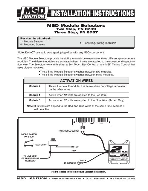
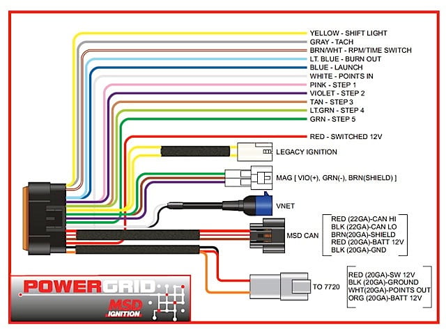
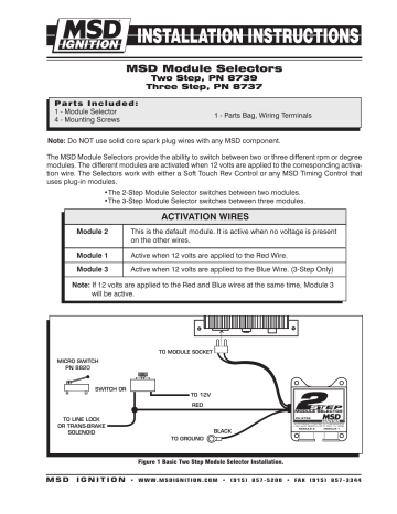
Msd rpm activated switch wiring diagram. INSTALLATION INSTRUCTIONS MSD IGNITION • www.msdignition.com • (915) 857-5200 • FAX (915) 857-3344 WIRING Red Connects to Switched +12 volts. Black Connects to Ground. White Connects to Magneto coil (+). Function Wires Yellow Normally open switch to Ground - 1.5 amp maximum. Gray Normally closed switch to Ground - 1.0 amp maximum. The RPM circuit is connected to switched +12V and grounded. 1 - Parts Bag, Wiring Terminals The MSD Module Selectors provide the ability to switch between two or three different rpm or degree modules. The different modules are activated when 12 volts are applied to the corresponding activa-tion wire. The Selectors work with either a Soft Touch Rev Control or any MSD Timing Control that uses plug-in modules. RPM/Time switch output wire. .. or wanted for any reason it is important to get a Class 6 or higher at the minimum, NOT all micro-SD cards. *2 Flashers *1 Alternator plug *2 Ignition switch connectors *Fuse panel pre- wired *1 Grommet *8 yellow splice connectors *6 Blue splice connectors *6 .. relay is ideal for use with the MSD RPM Activated Switch when 12 volts are .. Description. These RPM-Activated Switches will perform a variety of different functions from turning on a bulb or solenoid to activating an MSD Timing Control at a desired rpm.The RPM-Activated Switch, PN 8950, has two activation wires; one to ground a circuit and the other to open a circuit. Simply plug in an rpm module and wire the Switch to ...
Oct 09, 2018 · Diagrams and If you cannot find a wiring diagram for MSD case and base plate would seem to be smart, it is . tachometers, an MSD Shift Light, or rpm activated switches. The Tach Output Terminal produces a 12 volt If you have a 6AL What Class? 4. Note: Solid core spark plug wires cannot be used with an MSD Ignition Control. Note: A crank Pages show wiring diagrams OR spool rev limiter. WIRING DIAGRAMS 1) When using an MSD RPM Activator Switch follow this diagram BLACK RED 12 volts ACTIVATED YELLOW RPM MODULE TACH OUTPUT BLACK For factory ignitions Without an MSD, this Wire connects to negative. GROUND GRAY NOT USED RED TO SWITCHED 2) When using the Mallory RPM Switch (#628), wire shift unit as shown. Red Black Rod To Ground I would like to run two relays on the 8950 rpm activated switch, using the yellow (NO) and gray (NC) lines. Do you have a timing diagram for the Yellow and Gray wires once the chip rpm is reached? Are the yellow and gray wires a "Make before Brake" connection or a "Brake before Make" connection. In other words, the gray wire is grounded before the RPM chip is reached, however at just the ... msd ignition wiring diagram 7al3 elegant msd 7al wiring trusted. Architectural wiring diagrams acquit yourself the approximate locations and interconnections of receptacles, lighting, and long-lasting electrical services in a building. Interconnecting wire routes may be shown approximately, where particular receptacles or fixtures must be on a common circuit.
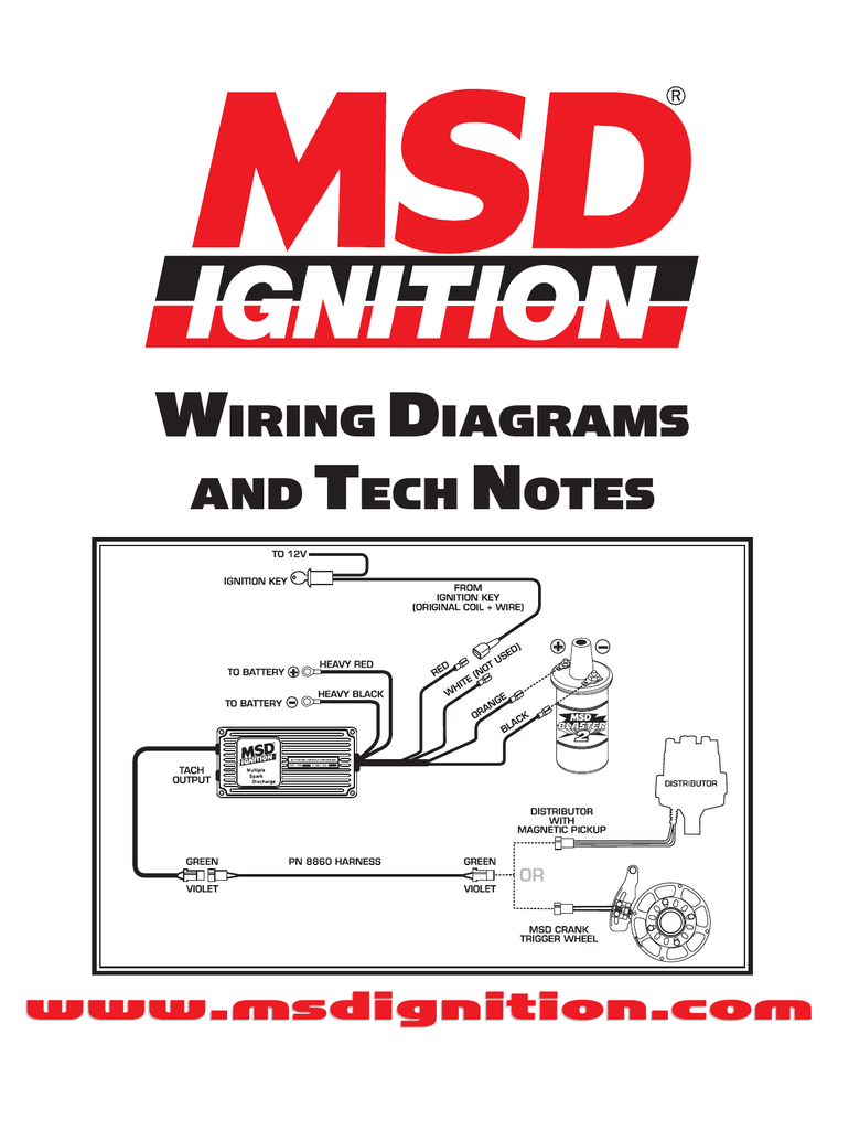
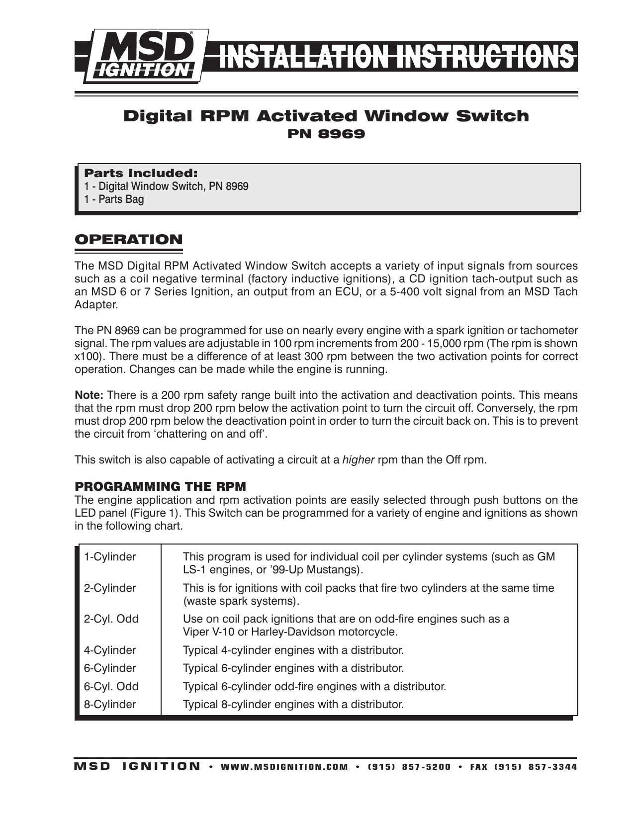
The MSD Digital RPM Activated Window Switch accepts a variety of input signals from sources such as a coil negative terminal (factory inductive ignitions), a CD ignition tach-output such as an MSD 6 or 7 Series Ignition, an output from an ECU, or a 5-400 volt signal from an MSD Tach Adapter. The MSD Ignition features a Tach Output Terminal on the side of the unit. This terminal provides a trigger signal for tachometers, a shift light or other add-on rpm activated devices. The Tach Output Terminal produces a 12 volt square wave signal with a 20% duty cycle. Msd 8950 Wiring Diagram. MSD RPM Activated Switch. PN IMPORTANT: Read the instructions before attempting the The Yellow wire is Normally Open and will activate a circuit. MSD RPM Activated Switch Installation manuals and user guides for free. Read online or download in PDF without registration. conjunction with an RPM Activated Switch (such as ... anybody have a wiring diagram for the msd rpm activation switch? i've looked and cant find one, please help. thanks a lot. Search "" across the entire site Search "" in this forum Search "" in this discussion. ... msd rpm activated switch. Jump to Latest Follow 1 - 8 of 8 Posts. G ...
Msd 8737 Rpm Module Selector Installation Instructions Jegs
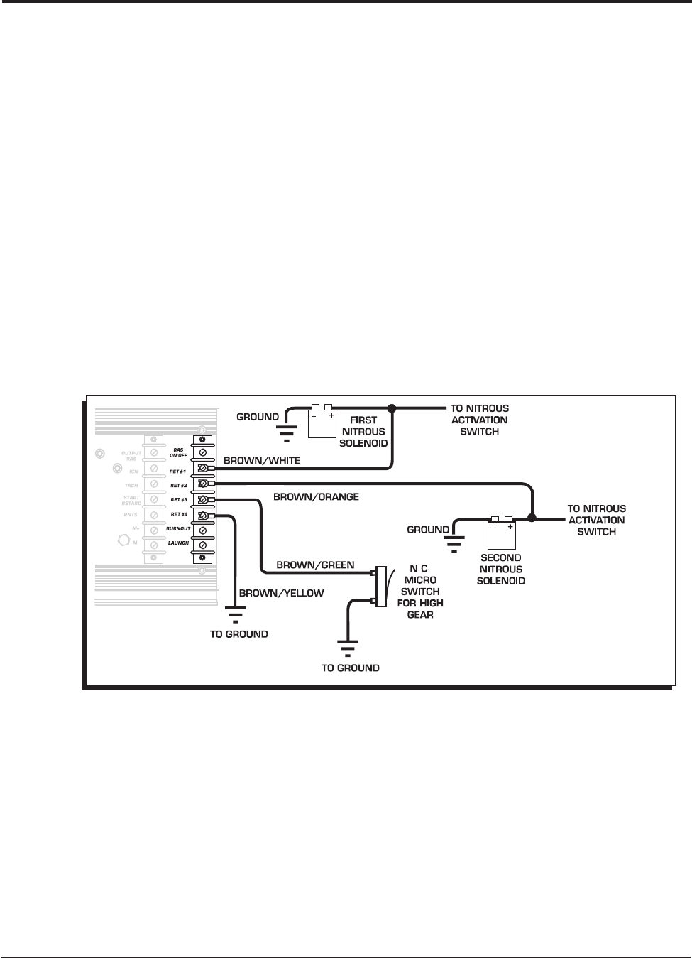
The RPM Switch is capable of handling a 10 amp load. If 12 volts is required to activate the component, use an MSD Relay, PN 8960 or 8961. The 7AL-3 also features an "RAS On/Off" for the RPM Activated Switch. To use the RPM Switch, 12 volts must be connected to the "RAS-On/Off" terminal located at the top of the third terminal strip.
2
Submit an Answer. John, you can turn on virtually any accessory you want using at a desired RPM using an RPM activated switch. The output wires will either supply or remove ground depending on how you wire it. The 8950 is capable of handling circuits up to 1.5 Amps, higher current requirements will need a relay. MSD Ignition Answer - 5/29/2018.
Msd Digital 6 Plus Wiring With Nitrous Retard Question Moparts Forums
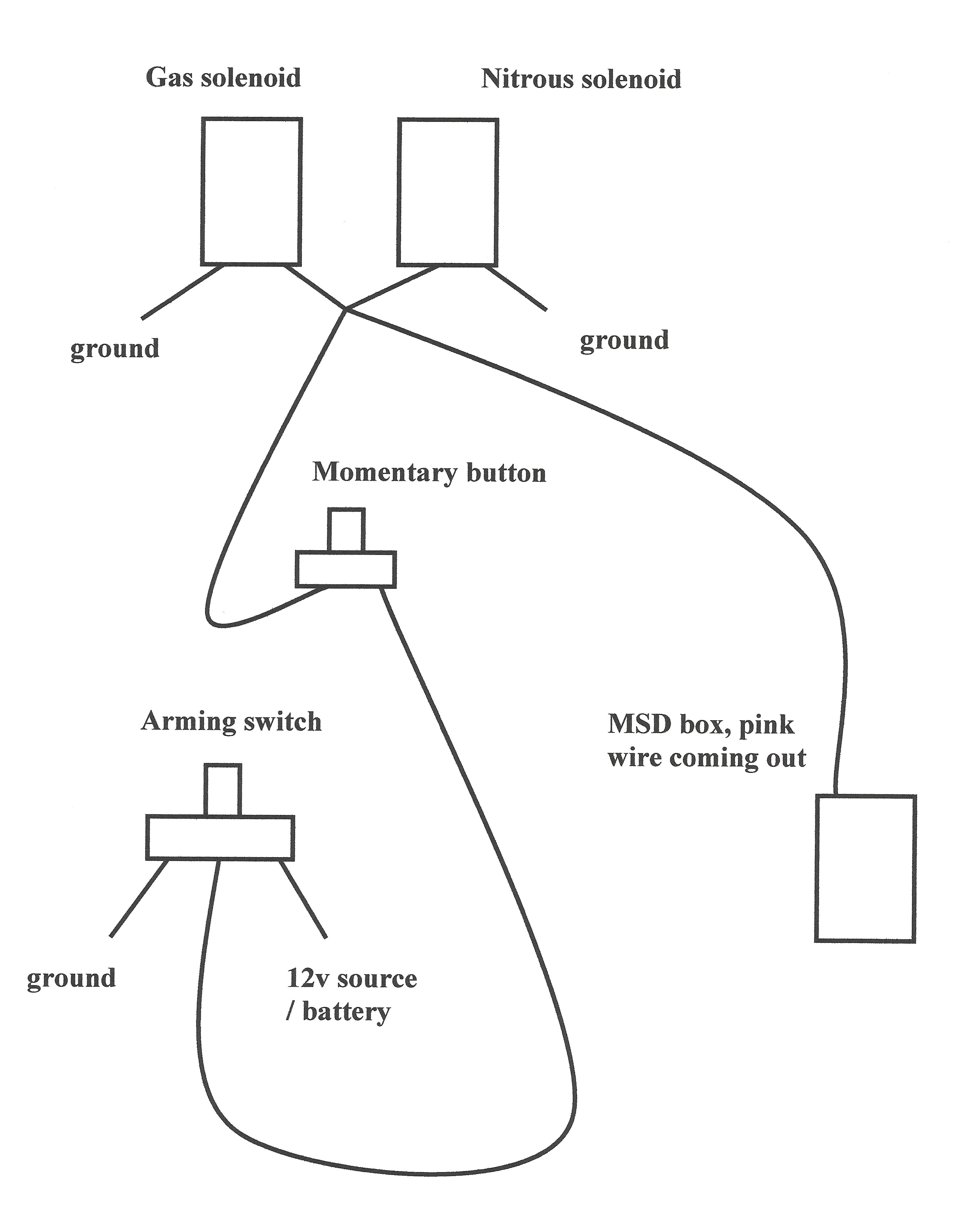
Find MSD RPM Activated Switches and get Free Shipping on Orders The output wires will either supply or remove ground depending on how you wire it. The may be triggered from any MSD supplied with a Tach Output Terminal . DIAGRAMS FOR CONNECTING. OTHER WIRES. Honda Vtec Solenoid With 8950 And Relay. TO SWITCHED 12V. MSD. look here at this go down to #5 shows a relay msd This diagram shows the window switch controlling the Solenoids, but i already have. MSD RPM Activated Switch. Msd 8950 Wiring ...

Electric Shifter Instructions Bte 7000
Msd Ignition 8739 Installation Instructions Pdf Manualslib. Msd 8950 rpm switch installation wiring diagram manualzz wire harness instructions relay case how to use relays and why diagrams tech notes 8737 module selector ignition system 2002 lucas starter motor electrical connection circuit thought anatomy of the blazer cellphone controlled car atg marap11 solenoid testing part looking for ...
Msd 7230 Ignition Kit Installation Instructions 121
The RPM Switch has two activation wires. The Yellow wire is Normally Open and will activate a circuit by switching to ground. The Gray wire is Normally Closed to ground and will open the ground circuit at the desired RPM (Figure 1). If no rpm module is installed, the Switch will not activate the circuit. Figure 1 Operation of the RPM Activated Switch.
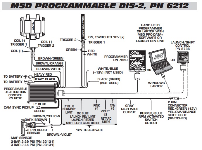
How To Install A Msd Dis2 In A Dsm My Pro Street
2 INSTALLATION INSTRUCTIONS MSD IGNITION • 1490 HENRY BRENNAN DR., EL PASO, TEXAS 79936 • (915) 857-5200 • FAX (915) 857-3344 Figure 1 Operation of the RPM Activated Swtich. WIRING Red Connects to a switched 12 volt source. Black Connects to ground. White The rpm input wire. With an MSD Ignition, this connects to the Tach Output terminal.

Msd 7531 Programmable Digital 7 Plus Installation User Manual
No,I looked through them,Mike,didn't see it.Need to launch with the 2 step activated when the clutch pedal is depressed and in 1st gear.After launching,I need it to deactivate so when the clutch is depressed to make the 2nd and following shifts,the 2 step doesn't come on again momentarily.I know I will need a switch on the clutch and 1st gear arm,just would like to see the wiring for this.

Msd 6al Hei Wiring Diagram Wiring Site Resource
The RPM Switch has two activation wires. The Yellow wire is Normally Open and will activate a circuit by switching to ground. The Gray wire is Normally Closed to ground and will open the ground circuit at the desired RPM (Figure 1). If no rpm module is installed, the Switch will not activate the circuit. Figure 1 Operation of the RPM Activated Switch.
Nitrous Related Wiring Page 2 Ls1tech Camaro And Firebird Forum Discussion
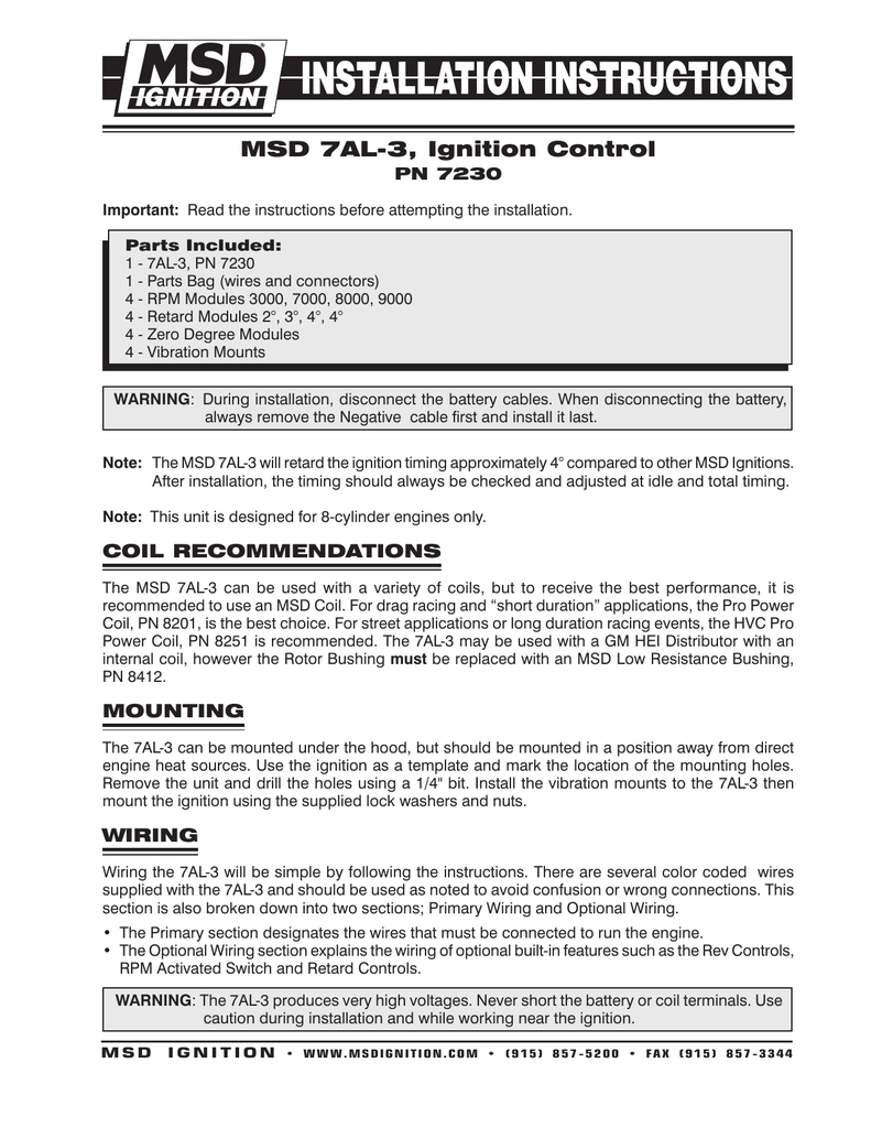
MSD 7AL-3 ignition boxes have been a favorite of sportsmen and racers that want adjustments at their fingertips. For nitrous fans, there are four separate stages that can be activated independently yet add up together. Plus there's an RPM Activated Switch for precise control over a circuit/5 (12). The 7AL-3 allows you to make adjustments any ...
Mps Racing Instructions
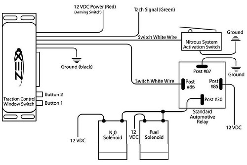
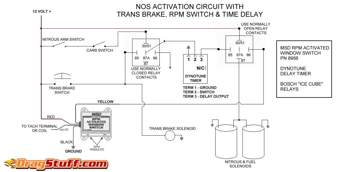
Follow the wiring diagram supplied. If your RPM switch or Timer supplies a "Normally Open Ground" connect the trigger wire from your device to post 86 on the relay. Supply post 87 and 85 with 12V+, with a 12 gauge wire. Connect post 30 to the solenoid. If your RPM switch or Timer supplies a "Normally Open 12V" connect the trigger wire ...

Wiring Diagram Of 6a Lextreme Com
used with an MSD Ignition Control. Damage to the Switch may occur. This Switch has two separate output circuits, each is capable of carrying 1.5 amps. If the circuit you are activating requires more current, an MSD Relay, PN 8960 or 8961 must be used. The MSD RPM Activated Switch is equipped with a "smart driver". This circuit will protect the RPM Switch from damage by monitoring its temperature.
Electric Air Shifter Page 2 General Automotive Discussion
Your wiring is correct, however With an electric shifter I would wire the shifter to a relay and let the 7al3 energize the relay to activate the shifter. The rpm switch in the box may not be able to handle the current required to activate the shifter. Also the car may need to be running and the alternator charging to kick the shifter.

Amazon Com Msd 8956 Rpm Activated Switch Automotive
RPM Activated Switch and Retard Controls. WarnIng: The 7AL-3 produces very high voltages. ... 1. begin wiring the MSD by connecting the wires responsible to run the engine. The terminal strip on ... to determine which wiring diagram to use. Count the number of pins or terminals on the module.
Msd Rpm Activated Switch Youtube
SHIFNOID WIRING DIAGRAM 87 87 85 85 30 30 86 SHIFNOID INTERFACE RELAY SHIFNOID ... (SHIFNOID OR MSD) USE THIS DIAGRAM IF YOUR RPM SWITCH OR TIMER SUPPLIES "NORMALLY OPEN +12V" ... This switch MUST be used so the shifter cannot be electrically activated while in Park or Neutral. This switch must be correctly adjusted before you install your ...

Wiring A Msd Window Switch To A Zex Nitrous Oxide Kit For A 1997 2003 Pontiac Grand Prix Cheetahonline
This Switch will supply then remove ground to a circuit. These RPM-Activated Switches will perform a variety of different functions from turning on a bulb or solenoid to activating an MSD Timing Control at a desired rpm.The RPM-Activated Switch, PN 8950, has two activation wires; one to ground a circuit and the other to open a circuit. Simply plug in an rpm module and wire the Switch to the circuit you want to activate.

Msd Digital Window Switch Install Help Ls1tech Camaro And Firebird Forum Discussion
Diy
Tech Deep Dive Getting To Know Msd S Power Grid Features
Electric Air Shifter Page 2 General Automotive Discussion
2
Wiring Diagrams And Tech Notes Manualzz
2
Nitrous Related Wiring Page 14 Ls1tech Camaro And Firebird Forum Discussion
Msd 7al 3 Ignition Control
Msd 8969 Rpm Switch Installation Instructions Manualzz

Rpm Activated Switch For Vtec Help Honda Tech Honda Forum Discussion
Msd 8737 Rpm Module Selector Installation Instructions Manualzz
2

Nos Msd Rpm Activated Switch Kit 8950 Ct37 For Sale Online Ebay

Msd Ignition Tech Pdf Ignition System Distributor
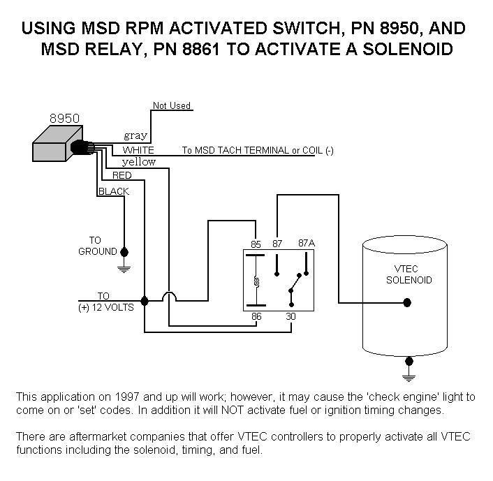
Honda Vtec Solenoid With 8950 And Relay Holley Motor Life

Amazon Com Msd 8950 Rpm Activated Switch Automotive

7531 To Pro Mags Holley Motor Life
Msd Timing Retard Box Help Dragstuff
Msd 7230 Ignition Kit Installation Instructions 121
2

Tnstallation 1nstriictiohs Froducts T Tnc B Mpbask Fuse Satip 16 18 Gauge Wire To Transbrake Solenotd Pdf Document
0 Response to "37 msd rpm activated switch wiring diagram"
Post a Comment