37 honeywell millivolt gas valve wiring diagram
Diagram honeywell gas valve wiring full version hd quality 4 diagrams 5 recommended spare parts millivolt frymaster sm60 user manual page 39 40 vs820 s manualzz 36e54 214 valves ef33cw233 control vr8200a2132 smart zone amkmns mynameisnique heater users 95c 10024b powerpile combination controls need help doityourself com community forums troubleshooting intermittent ignition th tr and terminals ... 02.11.2021 · Honeywell gas control valve 5 flashes reset. Honeywell gas control valve 5 flashes reset Honeywell gas control valve 5 flashes reset ...
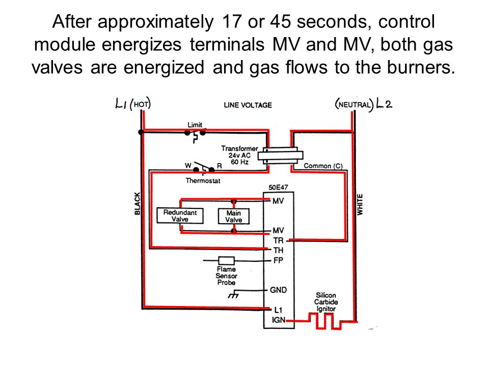
VS8420C,M MILLIVOLT GAS VALVE 69-1304 4 Fig. 5. Proper use of wrench on gas valve. Wiring Follow the wiring instructions furnished by the appliance manufacturer, if available, or use the general instruc-tions provided below. Where these instructions differ from the appliance manufacturer, follow the appliance manufacturer instructions.
Honeywell millivolt gas valve wiring diagram
The VS8420 Millivolt Gas Valve is compact and has a ... Millivolt wiring system wiring diagram with ... Honeywell Limited-Honeywell Limitée. Honeywell Plaza.8 pages Honeywell Millivolt Gas Valve Wiring Diagram. In order to improve service, have the following chart filled in by the Dean Authorized Service. Technician . A manual gas shut-off valve must be installed in the gas supply line ahead of the fryers for Honeywell Millivolt Gas Valve Wiring. The VS Millivolt Gas Valve is compact and has a Before ... The VS8510, VS8520 Millivolt Gas Valve is compact and ... Millivolt system wiring diagram without ... Honeywell Limited-Honeywell Limitée. Honeywell Plaza.8 pages
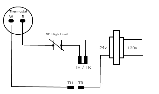
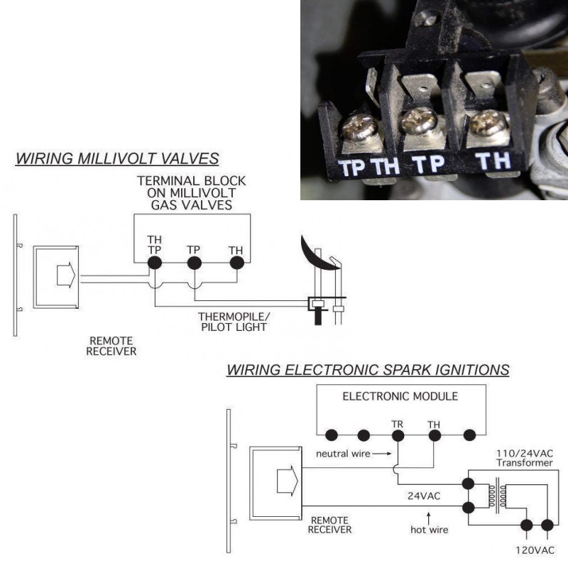
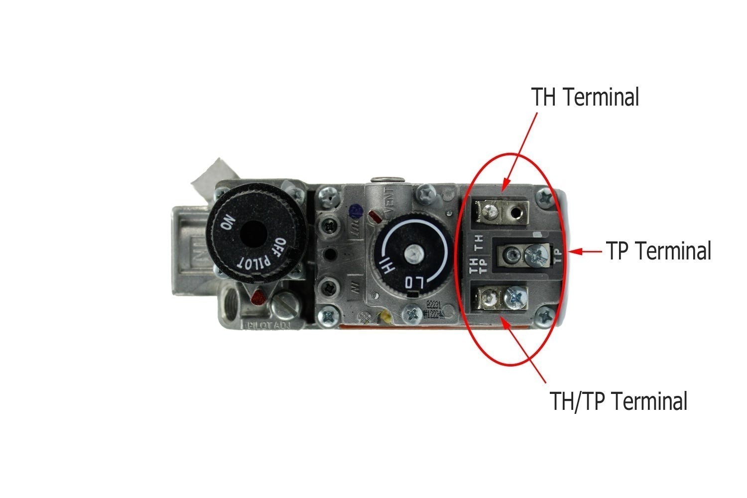
Honeywell millivolt gas valve wiring diagram. This is How to Wire the Thermopile to The 750mv Gas Valve for the Pilot and Main Gas Burners. This includes a WIRING DIAGRAM. I show you how to Light the Pil... This replacement kit may contain a Honeywell or a Robertshaw gas valve. ... Referring to wiring diagram "D" and figure "B", Connect BLUE wire to TH Terminal ...4 pages The VS8510 and VS8520 millivolt gas valves are approved ... Honeywell, 1885 Douglas Drive North ... VS8520 Millivolt system wiring diagram with quick.12 pages Honeywell Millivolt Gas Valve Wiring Diagram. Effectively read a wiring diagram, one offers to learn how typically the components in the method operate. For instance , in case a module will be powered up and it sends out a signal of half the voltage and the technician will not know this, he'd think he has a problem, as this individual would ...
Associate membership to the IDM is for up-and-coming researchers fully committed to conducting their research in the IDM, who fulfill certain criteria, for 3-year terms, which are renewable. 1.8 Wiring Diagrams 1-14 1.8.1 Current Production Units with Honeywell Gas Valve (Non-CE) 1-14 1.8.2 Current Production Units with Honeywell Gas Valve (CE) 1-15 1.8.3 Current Production Units with Robertshaw Gas Valve (After May, 2002) 1-16 1.8.4 UFF Filtration Wiring Diagram 1-17 capacity, compact-sized, millivolt-operated gas valve designed for ... VS8520 valve has operator powered by 750 mV thermopile ... WIRING DIAGRAMS. See Fig. ROBERTSHAW TO HONEYWELL MILLIVOLT GAS VALVE ... Disconnect the pilot generator and operating thermostat wiring from the valve. ... WIRING DIAGRAM FOR.
Honeywell Vs820 Gas Valve Wiring Diagram Standard Pilot Gas Valve 24v 1 2 X 3 4 Inlet Outlet Size. Honeywell Vs820 Gas Valve Wiring Diagram Vs820a 1013 Naturliche Honeywell Vs820a 1047 Powerpile Erdgas Ventil Neu Ebay. Honeywell Vs820 Gas Valve Wiring Diagram V800a1088 U. Honeywell Vs820 Gas Valve Wiring Diagram Standard Powerpile Millivolt ... DEAN MILLIVOLT SERIES GAS FRYERS (NON-CE). CHAPTER 6: TROUBLESHOOTING. 6-3. 6.4 Wiring Diagrams. Honeywell Millivolt Gas Valve Wiring. Thermostat. Operating. Honeywell Millivolt Gas Valve Wiring Diagram Source: diagramweb.net READ 2003 Infiniti G35 Radio Wiring Diagram For Your Needs Before reading a new schematic, get acquainted and understand all of the symbols. Honeywell Millivolt Gas Valve Wiring Diagram – wiring diagram is a simplified enjoyable pictorial representation of an electrical circuit.It shows the components of the circuit as simplified shapes, and the capacity and signal contacts between the devices.
Silo Tips
31.10.2021 · Note While relay wiring can use any available cable/conduit entry in the XNX enclosure, do not use the Honeywell XNX Transmitter Honeywell XNX is a flexible transmitter that can be configured to accept an input from any of the Honeywell Analytics range of gas sensor technologies. honeywell. 6. 1 of the XNX manual). Get info of suppliers, manufacturers, exporters, traders of Digital Transmitter ...

Robertshaw Millivolt Troubleshooting Guide Gas Products Ppt Video Online Download
Diagram robertshaw gas valve wiring full version hd quality 700 720 series two stage valves diagrams manualzz 7000 der derhc wire manual installation data 4 5 recommended spare parts honeywell millivolt frymaster sm60 user page 39 40 710 low capacity heating controls 0 item s 00 menu home products thermocouples thermopiles pilots ignitors flame sensors ignition modules cooking… Read More »
1
The VS8510, VS8520 Millivolt Gas Valve is compact and ... Millivolt system wiring diagram without ... Honeywell Limited-Honeywell Limitée. Honeywell Plaza.8 pages
Pitco 60125201 Cl Gas Valve Honeywell Natural Gas Millivolt Parts Town
Honeywell Millivolt Gas Valve Wiring Diagram. In order to improve service, have the following chart filled in by the Dean Authorized Service. Technician . A manual gas shut-off valve must be installed in the gas supply line ahead of the fryers for Honeywell Millivolt Gas Valve Wiring. The VS Millivolt Gas Valve is compact and has a Before ...

Thermopilot Valves Heater Service Troubleshooting
The VS8420 Millivolt Gas Valve is compact and has a ... Millivolt wiring system wiring diagram with ... Honeywell Limited-Honeywell Limitée. Honeywell Plaza.8 pages

Millivolt Models Nmv 2 Pmv 2 Infra Red Radiant
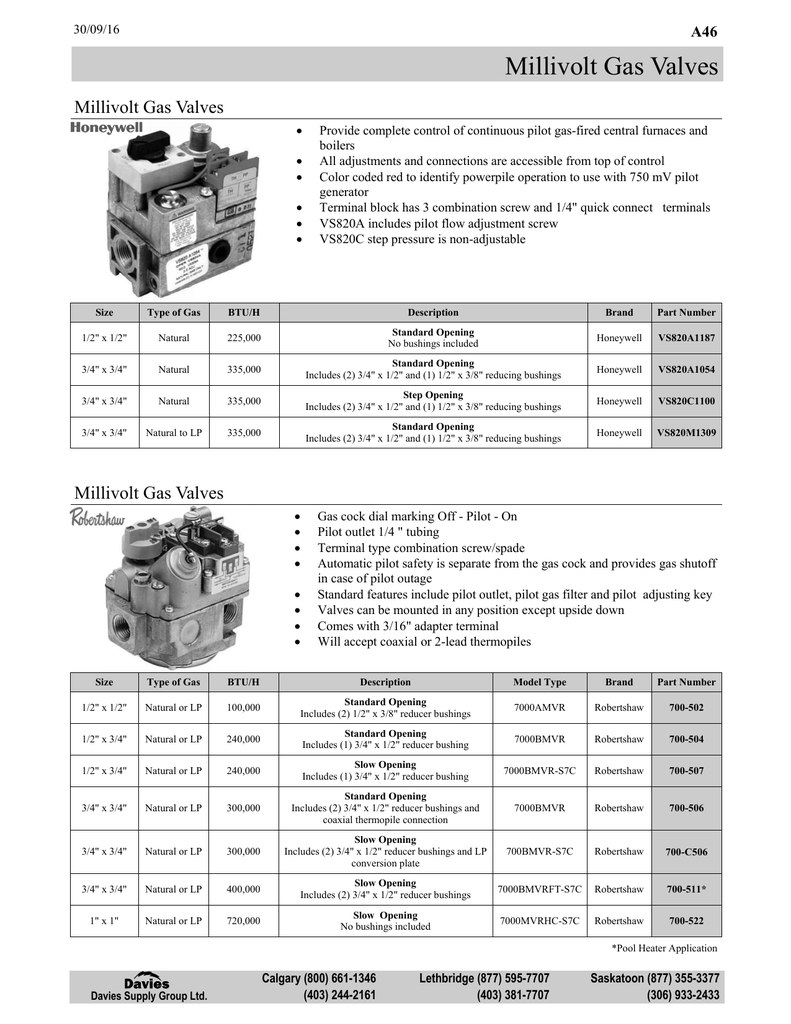
Millivolt Gas Valves Davies Supply Group Ltd Manualzz
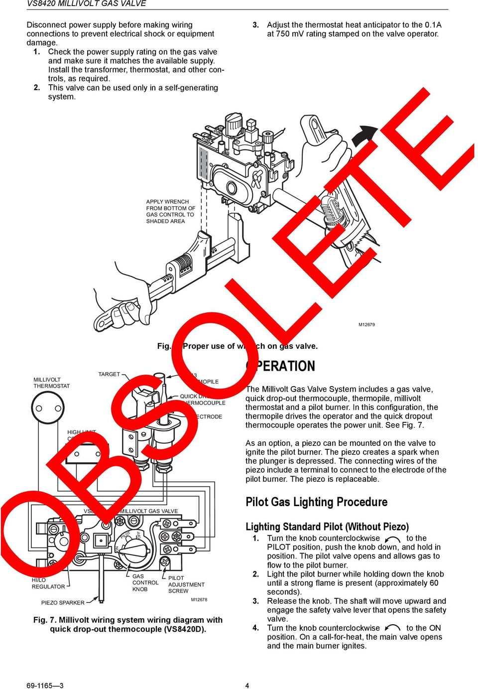
Obsolete Vs8420 Millivolt Gas Valve Pdf Free Download
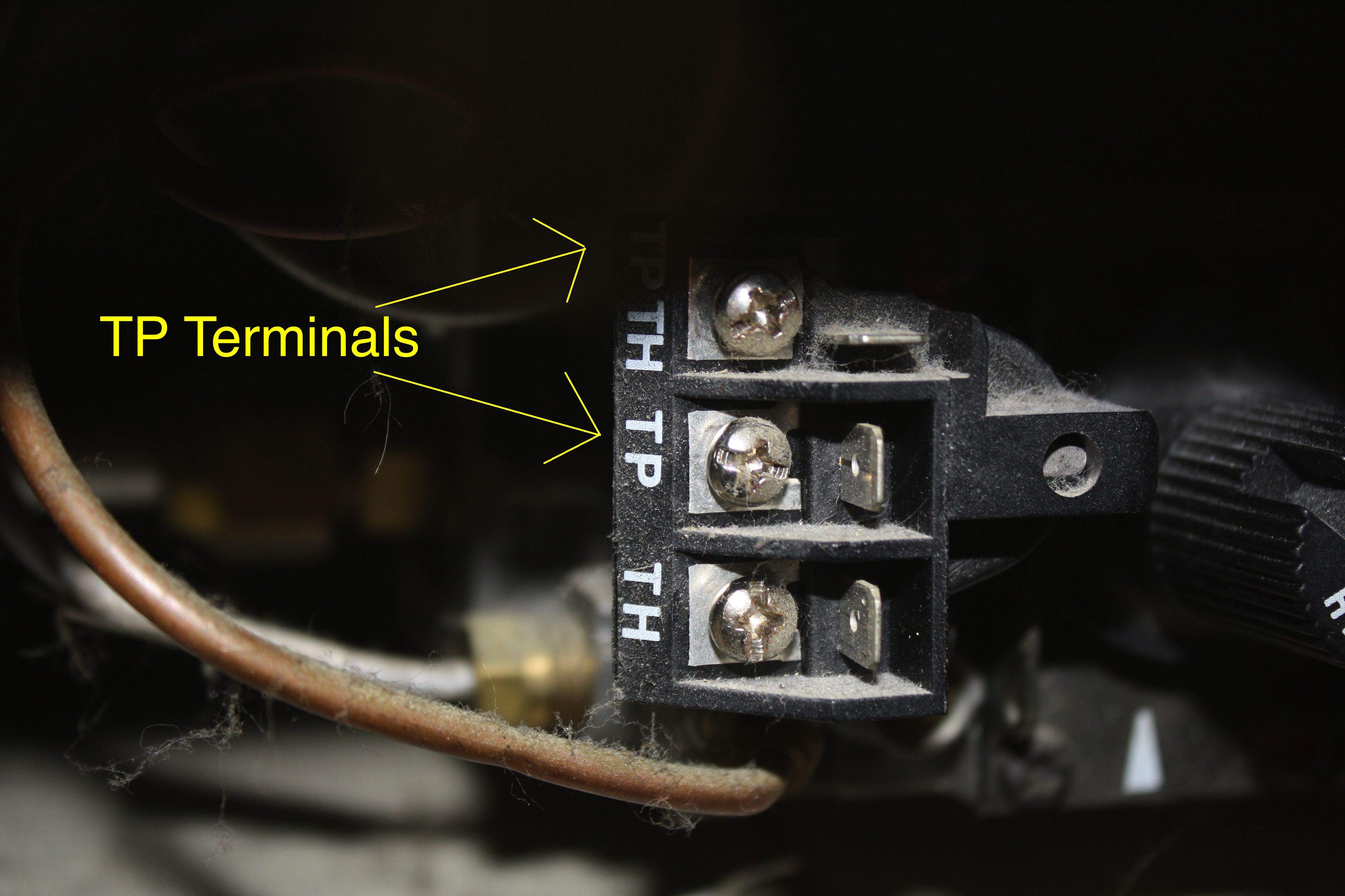
Th Tr And Th Tr Gas Valve Terminals Hvac School

Dakota Supply Group 750 Mv Thermopile 35 Long With Push In Clip And Split Nut

How To Wire Light The Pilot Power The Combination Gas Valve Youtube
Th Tr And Th Tr Gas Valve Terminals Hvac School

Honeywell Inc Vs8420e2113 Vs8420 Millivolt Gas Valve At Controls Central

Honeywell Millivolt Gas Valve Wiring Diagram Chrismacksmellslikecheese

How To Find The Right Thermostat For My Gas Fireplace Home Improvement Stack Exchange

Gas And Oil Controls Fenkojly Fankojly Ventilyatornye Dovodchiki

Pitco Millivolt Troubleshooting Youtube
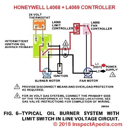
How To Install Wire The Fan Limit Controls On Furnaces Honeywell L4064b All White Rodgers Fan Limit Controllers

Honeywell Millivolt Gas Valve Wiring Diagram Chrismacksmellslikecheese

Gas Valve Wiring Diagram Mynameisnique
Vr8200a2116 T 24vac Dual Standing Pilot Gas Valve Quad Industry Gmbh
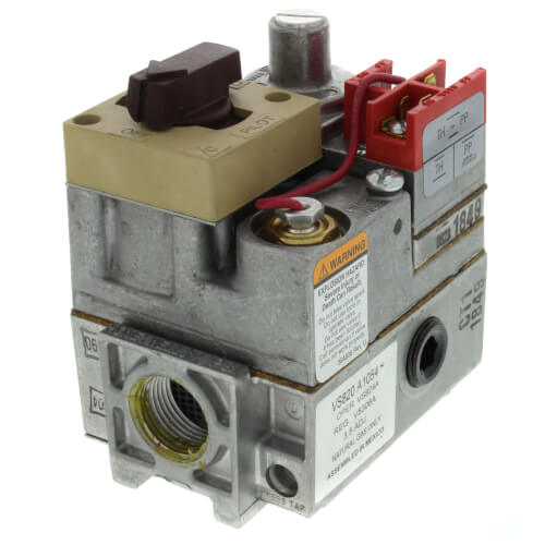
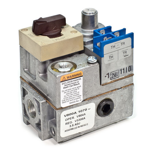
Vs820a1054 Resideo Vs820a1054 Standard Powerpile Millivolt Combination Gas Valve 3 4 Npt X 3 4 Npt
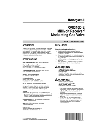
Rv8310d E Millivolt Receiver Modulating Gas Valve Application Manualzz
Gas Furnace Controls Part Ppt Video Online Download

Superior Dr500 Honeywell Electronic Gas Valve Sit Millivolt Gas Valve Honeywell Millivolt Gas Valve
Troubleshooting Gas Pool Heaters Pool Spa News
How To Test Your Main Control Valve Www Mygasfireplacerepair Com
Skytech Remote Control Kit For Gas Fireplaces
2
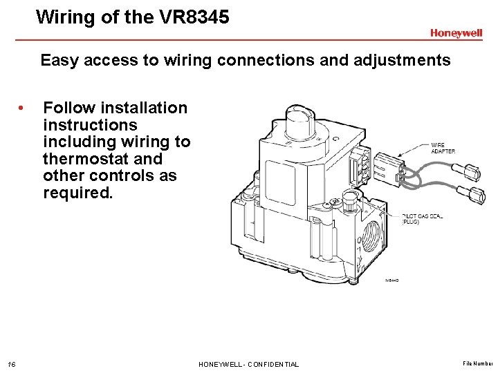
Vr 8345 Universal Electronic Ignition Gas Valve Training
What Fireplace Remote Control Works For You Skytechfireplaceremotes Com
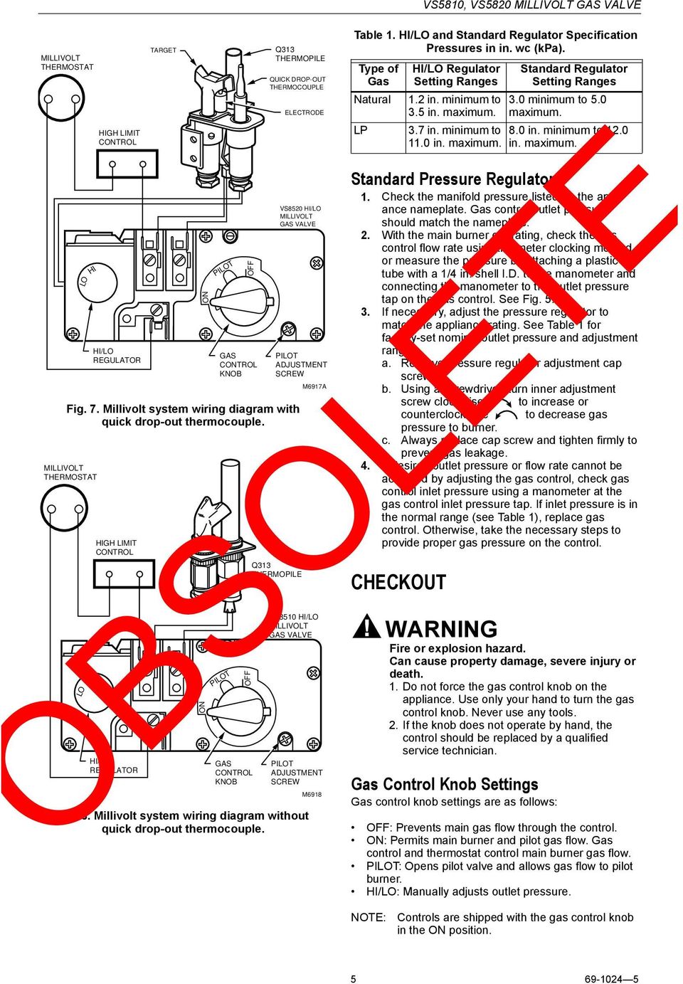
Obsolete Vs8510 Vs8520 Millivolt Gas Valve Pdf Free Download
Vr8304m4507 U
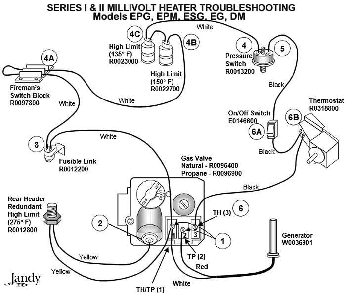
Millivolt Pool Heater Troubleshooting Guide Intheswim Pool Blog

Honeywell Millivolt Gas Valve Wiring Diagram Chrismacksmellslikecheese

Thermopilot Valves Heater Service Troubleshooting
V8944l1025 U 1 1 4 In Npt 2 Stg Diaphragm Gas Valve Quad Industry Gmbh
0 Response to "37 honeywell millivolt gas valve wiring diagram"
Post a Comment